Dense Geometry Compression Format SDK
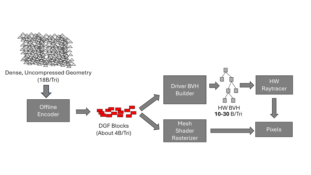
Dense Geometry Compression Format (DGF) is our block-based geometry compression technology. It is a hardware-friendly format, supported by future GPU architectures.
With the Dense Geometry Format (DGF), AMD introduced a cache-friendly representation for compressed triangles. Since future GPU architectures will support DGF, there is an opportunity to revisit different parts of the graphics programming stack that may utilize and benefit from DGF.
Our AMD DGF SDK was recently updated with bug fixes, improvements, and new features. One of our most exciting new features is the addition of an animation-aware encoding pipeline. You can refer to the release notes for a full list of changes.
In this blog post, we take a look at animations and how they work with DGF. Animating a mesh is achieved by manipulating vertex positions across multiple frames, creating an illusion of movement. Our key idea is to overwrite the positions inside a DGF block with animated positions in each frame.
We explain how to create animations with DGF and how you can use those animations in your ray tracing applications.
But before we dig into the details of animations, let’s recap DGF and linear vertex blend animations.
DGF, introduced at High Performance Graphics 2024 [1] by AMD, is a hardware-friendly format for storing compressed triangle meshes. As part of a pre-process, the AMD DGF Baker decomposes a triangle mesh into small meshes, or short meshlets. The DGF Baker then compresses those meshlets individually. A DGF-meshlet consists of up to 64 positions and 64 triangles. The meshlet is stored in a 128-byte DGF-block along with meta information. A set of DGF-blocks then represents a mesh.
A DGF block consists of three parts: a header, a geometry part, and a topology part:
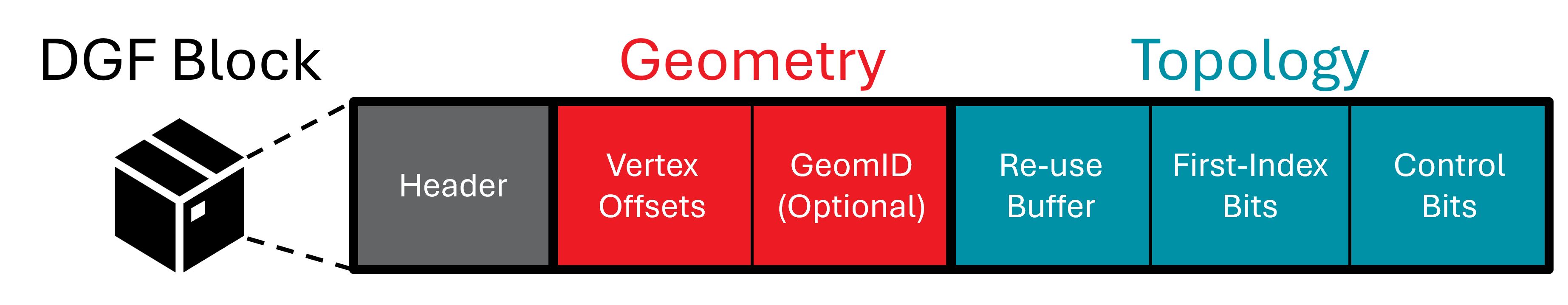
For this blog post, we need to understand the details of header and the geometry part. You only need a basic understanding of the topology part, so let’s start with that.
The topology part holds triangle connectivity: In a conventional representation, you would use an index buffer, where three indices define a triangle.
In terms of memory, storing the indices per triangle is hefty. Given 64 vertices per DGF block, we would need 6 bits to address a single vertex. A triangle with three vertices would then require bits. Instead, DGF stores topology as a generalized triangle strip with backtracking. That requires only about 5 bits per triangle stored in a re-use buffer, by the first index-bits, and the control bits, as shown in the figure above.
Initially, we proposed a sequential -algorithm [1] at High Performance Graphics 2024. But at Eurographics [2], we showed multiple data-parallel -algorithms. We were even able to deduce a random access version.
The figure above shows that the geometry part consists of vertex offsets and an optional GeomID part. For our goal of doing animations, you only need to understand what is meant by vertex offsets and neglect the GeomID part.
Each DGF block stores up to vertex offsets , < from which we compute the vertex positions :
First, we store vertex offsets with respect to a 3D anchor point . We use to offset the vertex offsets (hence the name). Each DGF block stores its own anchor in its header using three signed 24-bit integers.
Second, each vertex offset contains three unsigned integer values to represent the three vertex channels , , and of the vertex offsets. For each channel, we use a fixed number of bits per DGF block. For that, we can choose between one and 16 bits per channel. That number of bits per channel is also stored in the header.
Finally, we need a scale factor . We store its biased exponent as an 8-bit unsigned integer in the DGF block header. We use the factor to scale the position to floating-point numbers which are required for ray tracing and rasterization.
To conclude, we compute a 3D vertex floating-point position from an unsigned integer offset , with
The AMD DGF Baker carefully quantizes the original positions to compute , , and to avoid unwanted cracks. For more details, see Section 4 of our original paper [1].
In this blog, we focus on animation techniques that keep the topology stable across the course of an animation sequence and only vary the vertex positions over time. This holds for popular animation methods found in practice: Examples are all techniques that fall in the category of blend shapes (also known as morph targets, shape keys) or skinning (also known as vertex blending, bone animation, rigging) [3], Chapter 4.
Here, we use a basic form of linear vertex blend for demonstration purposes. But we believe that the basic idea we demonstrate here can easily be extended to more sophisticated animation methods.
Next, we explain the key idea of our animation pipeline. We use boldface to refer to entities shown in the following figure:
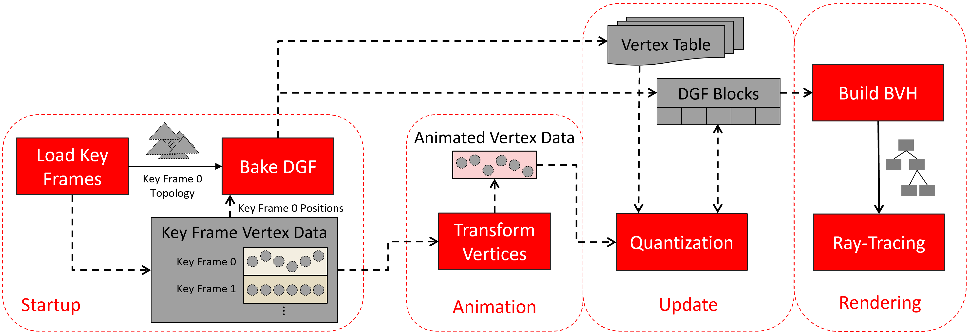
During Startup, we load all animation key frames (Load Key Frames). As said, the animation type we use here transforms vertex data, only, and keeps the topology stable for all key frames. We exploit this fact and Bake DGF for a single key frame, using only Key Frame Topology 0 and Key Frame Positions 0.
During baking (DGF Bake), we reserve space for the vertex positions inside the DGF blocks. This space will be filled with animated positions later. The topology part of a DGF block contains the immutable triangle connectivity information. After baking, we upload the resulting DGF Blocks.
During Startup, we upload the Key Frame Vertex Data (e.g., positions plus normals in our example) of all our key frames to the GPU.
After startup, we perform the steps Animation, Update, and Rendering each frame:
During Animation, we Transform Vertices with a compute shader. The compute shader reads the Key Frame Vertex Data from two neighboring key frames and interpolates between them. The mathematics behind is what you saw in our section on linear vertex blend animations above. We store the output in the Animated Vertex Data.
During Update, we Quantize the Animated Vertex Data and overwrite the positions in the corresponding DGF Blocks. We get to this in the section on Quantization further down.
Note that, after DGF baking, vertex positions can end up in multiple DGF blocks. To map a vertex index inside a DGF block to a vertex in the Animated Vertex Data/Key Frame Vertex Data, the DGF Baker outputs a Vertex Table that we keep on the GPU. We use that table to scatter the quantized and animated positions to its associated DGF Blocks. You find those details in the next section on Adjusting the DGF Baker.
With this, it becomes possible to animate each vertex only once and pull the updated positions into new DGF blocks. This allows free manipulation of vertex data, using different key frames, interpolation of vertices, etc.
Next, we will go into the details of Adjusting the DGF Baker and how our Quantization approach works.
AMD’s DGF Baker lets you create compressed DGF meshes from arbitrary triangle meshes. The DGF Baker is a C++ library. For more details on how to use the baker in your C++ program, see the DGF SDK Documentation here.
To bake a DGF mesh, you need to call BakeDGF method on a DGFBaker::Baker object.
You create your DGFBaker::Baker object by passing a config struct DGFBaker::BakerConfig config = {} to the constructor.
The DGF vertex offsets are limited to 16 bits in size. If a vertex drifts too far from its anchor point, the offset can overflow, resulting in severe artifacts. For static geometry, the DGFBaker prevents this overflow by selecting a quantization exponent based on the dimensions of each triangle cluster. This process is described in detail in our HPG paper.
For animated geometry, because we do not know the animated vertices at bake time, the value of must be chosen more conservatively.
Make sure to set config.quantizeForAnimations to true, when using animations.
By this, the quantization factor is chosen based on the diagonal length of the cluster AABB.
When set to false the x, y, and z extents are used.
Using the diagonal-length prevents offset overflow in the event that a cluster rotates during animation.
Another field for animation is the config.clusterDeformationPadding field.
It is a floating-point multiplier that scales the cluster AABBs when selecting a quantization exponent.
The purpose of this field is to add some padding to account for local stretching in the animation.
Again, this is necessary to prevent offset overflow.
We use the option config.blockForcedOffsetWidth to assign a fixed, predefined precision for each of the X, Y, and Z coordinates.
Usually, the DGF Baker computes a flexible bit-width for each channel, allowing further compression potential. However, we create our DGF blocks using a single key frame and ignore the other key frames. If we only used the bit-widths from one key-frame, other key-frames positions (and interpolated positions) would not fit in the bit-budget. We need, however, a bit-width that fits all key frames and all interpolated frames in between.
The animation sample currently supports config.blockForcedOffsetWidth for 16 bits for each component, 12 bits for each component, 8 bits per component.
Additionally, our sample supports a mixed precision bit width, where the x and y component use 11 bits and the z component uses 10 bits.
The DGF baker has the config.generateVertexTable option, which outputs a Vertex Table.
This table maps the vertex index inside a DGF block back to its original index in the input vertex array. Note, that the DGF baker duplicates input vertex positions and scatters them across multiple DGF blocks. This mapping allows us to manipulate the vertex data, without a need to extract the vertices inside a DGF block. Instead, we can directly read it from the Key Frame Vertex Data and write it to the Animated Vertex Data. By this, we only need to transform each vertex once during Animation. Eventually, we use the Vertex Table to update the positions inside DGF blocks during Quantization.
The user-data field is an optional part of the DGF block, located after the DGF header.
Its size is 32 bits.
We need this field to store the vertex offset of the block.
With the offset, we can retrieve the global vertex index for each local vertex in a given DGF block.
The option for this is called config.enableUserData and needs to be set to true.
To sum up, the minimal configuration to get animation is:
DGFBaker::Config bakerConfig = { .blockForcedOffsetWidth = {16, 16, 16}, // {12, 12, 12}, {8, 8, 8}, or {11, 11, 10} .generateVertexTable = true, .enableUserData = true, .quantizeForAnimation = true, .clusterDeformationPadding = 1.03f};The DGFBaker selects its quantization exponent based on the bounding box of the vertex coordinates. Larger coordinates require larger quantization factors to prevent the 24 bit anchors from overflowing. Animated vertices can easily drift outside of the initial bounding box, so a more conservative bound is required.
For animations, we provide a method BakerMesh::SetAnimationExtents to define a custom 3D bounding box.
You can use this to tell the DGFBaker what the bounds of your animation are.
By this you ensure that the DGF block anchors do not overflow in case the extents are too large to fit in 24 bits.
The following code shows how to set the animation extents:
DGFBaker::BakerMesh mesh(vertices, indices, numVerts, numTris);
DGFBaker::AnimationExtents extents = {};float extentMin[3] = ...; // compute animation bounding boxfloat extentMax[3] = ...; // (NOT SHOWN)extents.Set(extentMin[0],extentMin[1],extentMin[2],            extentMax[0],extentMax[1],extentMax[2]);// add the animation extents to the baker meshmesh.SetAnimationExtents(extents);
If the animation extents are not specified at baking time, the bounding box of the vertices will be used instead, which may not be sufficient.
In our sample application, we compute the exact bounding box of the vertex animation. If the animation is not known in advance, a simple heuristic, such as padding the rest-pose bounding box by an arbitrary factor, can also work well.
After animation, each floating-point position requires re-quantization before we can insert it back into the DGF block. We use a separate quantization compute shader to do this efficiently. In this section, we refer to the source code that comes with this blog post.
We launch the compute shader with one thread group for each DGF block and a wave size of 32.
We use 32 instead of 64, because the fixed bit width limits the vertex count to be less than 32.
While this might not seem to be the most optimal choice, we will show in the Results section, that the runtime of this compute kernel is negligible.
Each thread, whose index is gtid (group thread ID), then manipulates one vertex.
Next, we describe the quantization process in more detail. We make use of the LDS (local data share) memory to allow quick read and write access: First, we load an entire DGF block into LDS. Thereby the group thread ID determines the block index.
We need an array of 32 DWORD’s to fit a DGF block with 128 Byte.
groupshared uint blockData[32]; // sizeof(uint) * 32 = 128 Bytes, i.e., size of a DGF block.
    ...
    {        blockData[gtid] = DgfBlockBuffer.Load(blockInfo.blockStartOffset + 4 * gtid);
        ...    }
As mentioned, we use a fixed vertex-channel width of different sizes.
We tightly pack the vertex data, and thus we pack one vertex into multiple DWORD’s with one DWORD being shared by up to three vertices.
We get the two DWORD indices a vertex covers using GetIndices.
However, manipulating the DWORD shared by two or more vertices requires additional synchronization.
We use atomic bit operations (i.e., InterlockedAnd and InterlockedOr) to safely write the respective section of a DWORD.
Depending on their byte address, we generate three bit masks for each thread using GetMasks.
We compute the masks such that we zero out the vertices that we want to overwrite:
const uint vertexIndex = gtid;  // use the group-thread id as vertex index within the DGF block.const uint vertexByteAddress = (vertexIndex * blockInfo.bitsPerVertex);
const uint3 indices = GetIndices(vertexBitAddress);const uint3 masks = GetMasks(vertexBitAddress, blockInfo.header.bitsPerComponent);
// Start location in 4 Byte incrementconst uint bitsPerByte = 8;const uint vertexStartIndex = blockInfo.header.bitSize / (bitsPerByte * 4);
if (gtid < blockInfo.header.numVerts){    InterlockedAnd(blockData[vertexStartIndex + indices.x], ~masks.x);    InterlockedAnd(blockData[vertexStartIndex + indices.y], ~masks.y);    InterlockedAnd(blockData[vertexStartIndex + indices.z], ~masks.z);}
After synchronization, we can start quantizing the vertex positions.
We fetch a thread’s designated vertex using the vertex table and vertex offset, which is stored in the user data of the DGF block.
After that, we quantize the vertex using the unbiased exponent .
The header stores the biased exponent in the lower parts of the second DWORD, which we extract and remove the bias.
We use wave intrinsic function WaveActiveMin to find the minimal value of each channel.
This minimum will be used as the new anchors for the block:
int3 quantizedPositions = int3(0x7fffffff, 0x7fffffff, 0x7fffffff);
if (gtid < blockInfo.header.numVerts){    const uint globalVertexIndex = VertexTable.Load(blockInfo.header.userData + gtid);    const float3 vertexPosition = Positions.Load(globalVertexIndex);    const uint headerDWORD1 = blockData[1];    const int unbiasedExponent = -((headerDWORD1 & 0xff) - 127);    quantizedPositions = Quantize(vertexPosition, pow(2, unbiasedExponent));}
const int3 anchor = WaveActiveMin(quantizedPositions);
We adjust the quantized vertex positions by subtracting the anchor from each channel. Then, we combine the three channels into one 64-bit-wide codeword. Since the codeword needs up to three DWORD’s to write, we need to separate it into multiple values and bit-shifting them accordingly. Again, this is dependent on the byte address. Using the bit masks from earlier, we can write the values in their position in the block using atomic or-operations:
if (gtid < blockInfo.header.numVerts){    const int3 offsetVert = quantizedPositions - anchor;    const uint64_t xbits = blockInfo.header.bitsPerComponent.x;    const uint64_t xybits = blockInfo.header.bitsPerComponent.x + blockInfo.header.bitsPerComponent.y;    const uint64_t codedVert = offsetVert.x | (offsetVert.y << xbits) | ((uint64_t) offsetVert.z << xybits);
    const uint3 values = GetValues(vertexBitAddress, blockInfo.header.bitsPerComponent, codedVert);
    InterlockedOr(blockData[vertexStartIndex + indices.x], values.x & masks.x);    InterlockedOr(blockData[vertexStartIndex + indices.y], values.y & masks.y);    InterlockedOr(blockData[vertexStartIndex + indices.z], values.z & masks.z);}
Finally, we need to update the block anchor, which we store in the block header.
Each anchor channel is stored in the upper three bytes of the second, third and fourth DWORD of the header.
We use bit masks and bit operations again, to leave other parts of the DWORD unchanged.
With WaveIsFirstLane, we make sure that only one thread writes the anchor.
if (WaveIsFirstLane()){ blockData[1] = (blockData[1] & 0x000000FF) | ((anchor.x << 8) & 0xFFFFFF00); blockData[2] = (blockData[2] & 0x000000FF) | ((anchor.y << 8) & 0xFFFFFF00); blockData[3] = (blockData[3] & 0x000000FF) | ((anchor.z << 8) & 0xFFFFFF00);}After synchronization, we write the new block data to memory and are finished with the quantization step.
We created a sample that utilizes this approach. In the following table, we break down the impact of the different steps on the frame time: We show results for various models (left column) from the The Utah 3D Animation Repository with varying triangle (second column) and vertex count (third column). The remaining columns show the time in milliseconds of the different stages of our pipeline (see DGF Animation Pipeline Overview). All timings were measured on an AMD Radeon™ RX 7900 XT graphics card.
| Triangle Count | Vertex Count | Animation (ms) | Quantization (ms) | BVH Build (ms) | Ray Trace (ms) | |
|---|---|---|---|---|---|---|
| wooddoll | 5378 | 3899 | 0.0018 | 0.0016 | 0.1953 | 0.4787 |
| marbles | 8800 | 4620 | 0.0018 | 0.0016 | 0.2020 | 0.5254 |
| toasters | 11141 | 5628 | 0.0018 | 0.0017 | 0.2440 | 0.5675 |
| hand | 15855 | 8636 | 0.0019 | 0.0018 | 0.2143 | 0.5280 |
| ben | 78029 | 41474 | 0.0025 | 0.0043 | 0.4108 | 0.7776 |
| 24-cell | 122880 | 63744 | 0.0030 | 0.0060 | 0.4516 | 1.0506 |
| fairyforest | 174117 | 96566 | 0.0036 | 0.0240 | 0.7646 | 1.0422 |
| explodingDragon | 252572 | 192859 | 0.0063 | 0.0135 | 0.7676 | 1.4074 |
Quantization took less than 1% of the overall frame time, which means this process will not majorly affect rendering times in an animation pipeline. Likewise, animating the position data (Animation) has an almost insignificant contribution to the frametime. BVH Build and Ray Trace dominate the image computation.
Next, we analyze how the fixed-bit channel width impacts the DGF compression capabilities.
We measure the triangle density, i.e., the average number of bytes per triangle.
In the column Static DGF, you see the density of a single key-frame data, with a target bit-width of 14.
This is for reference, to assess how a single key frame would compress with DGF.
The column Uncompressed shows the density of a conventional indexed-face set (floats for positions and integers for indices) would require.
The remaining columns are triangle densities that we measured with our sample when performing animation. The columns show the different options we used for config.blockForcedOffsetWidth. Numbers in parentheses are the ratios relative to static DGF.
| Static DGF | Uncompressed | 16 16 16 | 12 12 12 | 11 11 10 | 8 8 8 | |
|---|---|---|---|---|---|---|
| wooddoll | 6.9 | 20.7 (3.0) | 13.4 (1.9) | 9.6 (1.4) | 8.8 (1.3) | 6.4 (0.9) |
| hand | 6.2 | 18.5 (3.0) | 12.1 (2.0) | 8.6 (1.4) | 7.6 (1.2) | 5.7 (0.9) |
| toasters | 6.6 | 18.1 (2.7) | 13.6 (2.1) | 9.9(1.5) | 8.8 (1.3) | 6.4 (1.0) |
| marbles | 4.8 | 18.3 (3.8) | 10.5 (2.2) | 7.4 (1.5) | 6.9 (1.4) | 4.8 (1.0) |
| ben | 5.2 | 18.4 (3.5) | 14.2 (2.7) | 9.9 (1.9) | 8.8 (1.7) | 6.6 (1.3) |
| fairyforest | 4.3 | 18.7 (4.3) | 14.0 (3.3) | 10.1 (2.3) | 8.9 (2.1) | 6.7 (1.6) |
| 24-cell | 6.4 | 18.2 (2.8) | 14.1 (2.2) | 9.5 (1.5) | 8.5 (1.3) | 6.8 (1.1) |
| explodingDragon | 5.6 | 21.2 (3.8) | 15.0 (2.7) | 10.8 (1.9) | 9.5 (1.7) | 7.0 (1.3) |
As expected, triangle density goes up for animations when using higher config.blockForcedOffsetWidth. This happens because a larger vertex size limits the number of triangles which will fit in a block, and results in more blocks. However, DGF is still capable of drastically reducing the memory footprint for triangle meshes over uncompressed geometry.
We have demonstrated that DGF is capable of handling animations efficiently. In particular, we are able to animate and update the DGF blocks for a 252K triangle scene in roughly 20 microseconds. This is due to the fact that we can access positions of DGF block in a random access fashion, when using bit operations during position update. This makes animating inexpensive and also negligible in terms of run-time performance.
At the same, we can benefit from the DGF compression ratios since triangles mesh become significantly smaller when encoding them with DGF even with animations.
The animation sample can be found in the updated version of the DGF SDK repository.
[1] J. Barczak, C. Benthin, and D. McAllister, “DGF: A Dense, Hardware-Friendly Geometry Format for Lossily Compressing Meshlets with Arbitrary Topologies”, Proc. ACM Comput. Graph. Interact. Tech., 2024.
[2] Q. Meyer, J. Barczak, S. Reitter, and C. Benthin , “Parallel Dense-Geometry-Format Topology Decompression” in Eurographics 2025 - Short Papers, 2024.
[3] T. Akenine-Möller, E. Haines, N. Hoffmann, A. Pesce, M. Iwanicki, S. Hillaire, “Real-Time Rendering 4th Edition”, A K Peters/CRC Press, 2018.