Vulkan® Memory Allocator
VMA is our single-header, MIT-licensed, C++ library for easily and efficiently managing memory allocation for your Vulkan® games and applications.
The AMD GCN Vulkan® extensions allow developers to get access to some additional functionality offered by the GCN architecture which are not currently exposed in the Vulkan® API. One of these is the ability to access the barycentric coordinates at the fragment-shader level.
When using AMD’s VK_AMD_shader_explict_vertex_parameter extension (which itself exposes the SPV_AMD_shader_explict_vertex_parameter extension in SPIR-V) to read the hardware-calculated barycentric coordinates, you need a workaround to output the coordinates from the fragment shader in the expected order.
Without the workaround, the current implementation will select the provoking vertex for the primitive based on its screen orientation. However, if you need to rely on the logical position of the barycentric coordinates, i.e. the barycentric coordinate zero at the first vertex of the primitive, then a workaround is needed.
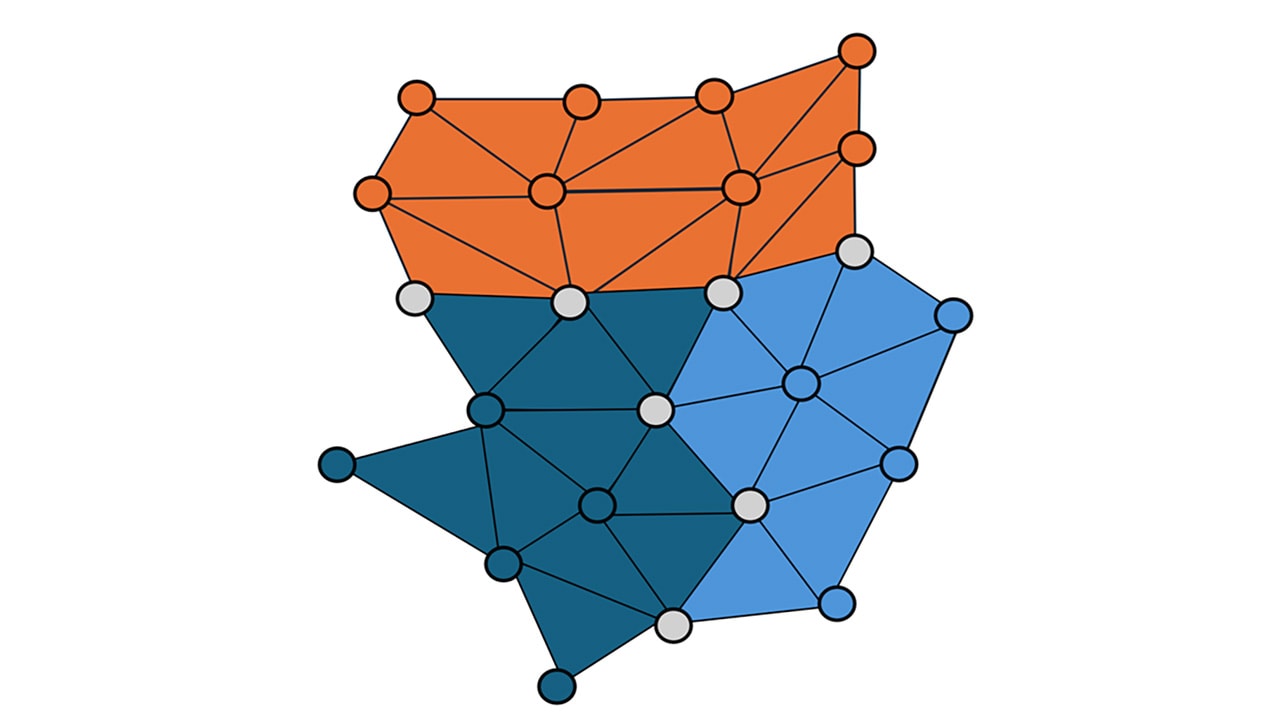
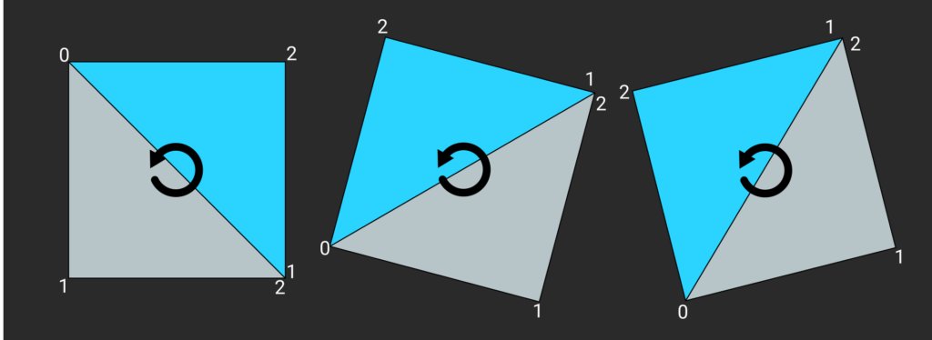
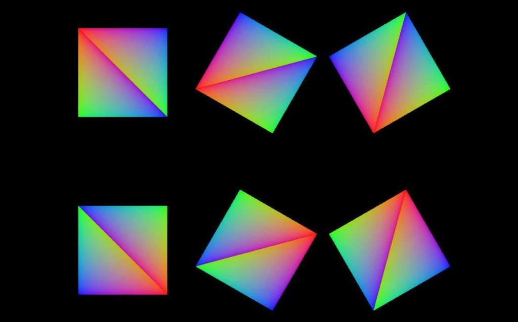
In order to better understand the problem, let’s visualise what happens when you output the barycentric coordinates directly from the fragment shader. In this example and the following one the mesh used is composed of two triangles forming a quad. This quad is rendered at different positions and multiple times using a call to vkCmdDrawIndexed and rotated by using 6 different model matrices indexed via gl_InstanceIndex in the vertex shader. The following image show how the primitives are arranged and the winding and rotation direction:
The vertex shader looks like this:
#version 450
#extension GL_ARB_separate_shader_objects : enable#extension GL_ARB_shading_language_420pack : enable#extension GL_ARB_shader_draw_parameters : enable
#define kProjViewMatricesBindingPos 0#define kModelMatricesBindingPos 0
layout (location = 0) in vec3 pos;
layout (std430, set = 0, binding = kProjViewMatricesBindingPos) buffer MainStaticBuffer {mat4 proj;mat4 view;};
layout (std430, set = 1, binding = kModelMatricesBindingPos) buffer ModelMats {mat4 model_mats[];};
void main() {gl_Position = proj * view * model_mats[gl_InstanceIndex] * vec4(pos, 1.f);}
Whereas the fragment shader looks like this:
#version 450#extension GL_ARB_separate_shader_objects : enable
#extension GL_ARB_shading_language_420pack : enable
#extension GL_AMD_shader_explicit_vertex_parameter : enablelayout (location = 0) out vec4 debug_out;void main() {
debug_out.xy = gl_BaryCoordSmoothAMD.xy;
debug_out.z = 1 - debug_out.x - debug_out.y;
}
Note the usage of #extension GL_AMD_shader_explicit_vertex_parameter : enable to enable the correct extension for the barycentric coordinates. That allows us to read the barycentric coordinates via gl_BaryCoordSmoothAMD.xy . In this example we read the barycentric coordinates with perspective interpolation at the fragment’s position.
The image produced is the following:
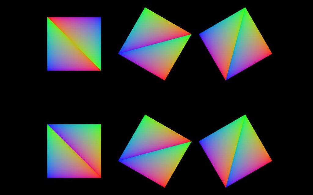
If the camera is rotated, the barycentric coordinates shift position due to the choosing of another provoking vertex by the implementation. Here, the camera is rotated just a bit in both directions as you can see on the top edge of the top-left box. Even this small rotation is enough to significantly change the output:
The fix consists of modifying both the vertex shader and the fragment shader as follows. Vertex shader first:
#version 450#extension GL_ARB_separate_shader_objects : enable
#extension GL_ARB_shading_language_420pack : enable
#extension GL_ARB_shader_draw_parameters : enable#define kProjViewMatricesBindingPos 0
#define kModelMatricesBindingPos 0layout (location = 0) in vec3 pos;layout (location = 0) flat out vec4 pos0;
layout (location = 1) out vec4 pos1;layout (std430, set = 0, binding = kProjViewMatricesBindingPos) buffer MainStaticBuffer {
mat4 proj;
mat4 view;
};layout (std430, set = 1, binding = kModelMatricesBindingPos) buffer ModelMats {
mat4 model_mats[];
};void main() {
vec4 temp = proj * view * model_mats[gl_InstanceIndex] * vec4(pos, 1.f);
pos0 = temp;
pos1 = temp;
gl_Position = temp;
}
And then the fragment shader:
#version 450#extension GL_ARB_separate_shader_objects : enable
#extension GL_ARB_shading_language_420pack : enable
#extension GL_AMD_shader_explicit_vertex_parameter : enablelayout (location = 0) flat in vec4 pos0;
layout (location = 1) __explicitInterpAMD in vec4 pos1;layout (location = 0) out vec4 debug_out;void main() {
vec4 v0 = interpolateAtVertexAMD(pos1, 0);
vec4 v1 = interpolateAtVertexAMD(pos1, 1);
vec4 v2 = interpolateAtVertexAMD(pos1, 2);if (v0 == pos0) {
debug_out.y = gl_BaryCoordSmoothAMD.x;
debug_out.z = gl_BaryCoordSmoothAMD.y;
debug_out.x = 1 - debug_out.z - debug_out.y;
}
else if (v1 == pos0) {
debug_out.x = gl_BaryCoordSmoothAMD.x;
debug_out.y = gl_BaryCoordSmoothAMD.y;
debug_out.z = 1 - debug_out.x - debug_out.y;
}
else if (v2 == pos0) {
debug_out.z = gl_BaryCoordSmoothAMD.x;
debug_out.x = gl_BaryCoordSmoothAMD.y;
debug_out.y = 1 - debug_out.x - debug_out.z;
}
}
We modified the shaders so that we can check the provoking vertex and modify the output accordingly. You can see that in the vertex shader we output two additional vec4 values:
layout (location = 0) flat out vec4 pos0;
layout (location = 1) out vec4 pos1;
pos0 is the non-interpolated vertex position which corresponds with the position of the provoking vertex by use of the flat directive. pos1 instead will use custom interpolation allowed by the GCN extensions. We can set custom interpolation to be used by adding the directive __explicitInterpAMD to an input variable in the fragment shader:
layout (location = 1) __explicitInterpAMD in vec4 pos1;We can then retrieve its raw value without interpolation (as it was in the vertex shader) by using interpolateAtVertexAMD() in the fragment shader:
vec4 v0 = interpolateAtVertexAMD(pos1, 0);
vec4 v1 = interpolateAtVertexAMD(pos1, 1);
vec4 v2 = interpolateAtVertexAMD(pos1, 2);
This gives us the value of the three vertices forming the primitive in homogeneous coordinates and we can then use them to compare them with the value in homogeneous coordinates of the provoking vertex, hence achieving our end goal of finding the provoking vertex and allowing our workaround.
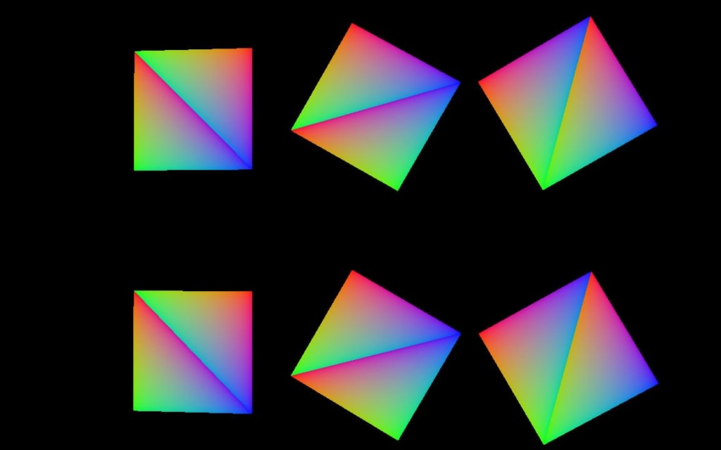
With the fix, the final render looks like this:
The location of the barycentric coordinates is now reliable and stable and can be used as a building block for more sophisticated rendering techniques and algorithms.