Introduction to raytracing with Radeon Developer Tool Suite
In this video, Can Alper introduces RRA V1.0. He explains how to capture games using RDP and evaluate when to use RRA.
Optimizing the raytracing pipeline has very different (and often conflicting) strategies compared to the rasterization pipeline in geometry creation and scene organization. The Radeon™ Raytracing Analyzer (RRA) can help you investigate these new strategies and mitigate bottlenecks.
This article will discuss some common pitfalls that developers may run into, how to diagnose them with RRA, and how to fix them. All of the following sample traces can be found in the RRA public GitHub page in the samples folder.
An inherent trade-off in ray tracing is bounding volume hierarchy (BVH) build time versus BVH traversal time. In general, building higher quality BVHs takes more time but results in more efficient ray traversal. The driver holds most of the responsibility to manage this trade off, taking into account build flags passed to the graphics API, such as:
D3D12_RAYTRACING_ACCELERATION_STRUCTURE_BUILD_FLAG_PREFER_FAST_TRACE or D3D12_RAYTRACING_ACCELERATION_STRUCTURE_BUILD_FLAG_PREFER_FAST_BUILD in DirectX® 12.
VK_BUILD_ACCELERATION_STRUCTURE_PREFER_FAST_TRACE_BIT_KHR or VK_BUILD_ACCELERATION_STRUCTURE_PREFER_FAST_BUILD_BIT_KHR in Vulkan®.
The developer, however, is responsible for grouping their application’s mesh data into geometries contained within bottom-level acceleration structures (BLASes) and placing instances of them into a top-level acceleration structure (TLAS). Instances whose bounding boxes occupy lots of empty space, or have significant overlap with other instances’ bounding boxes can hurt traversal performance. A common example of that issue is to make a game’s terrain one big BLAS, with a bounding box overlapping everything in the scene.
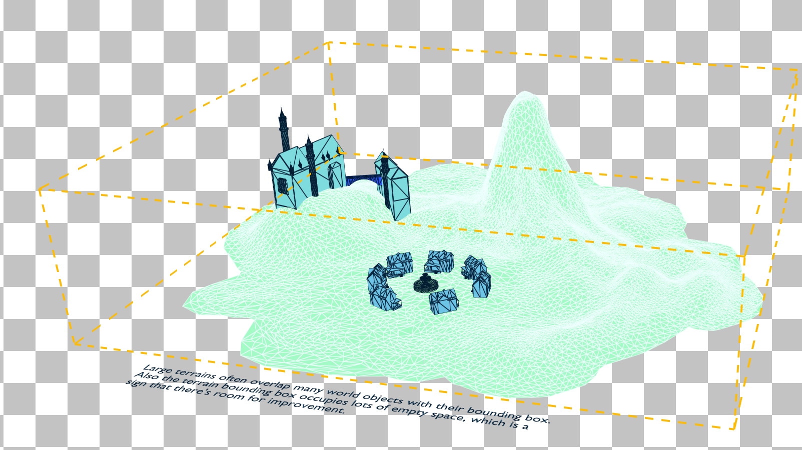
In the image above, we see that the houses and castle are completely enclosed by the terrain’s bounding box, which also occupies lots of empty space.
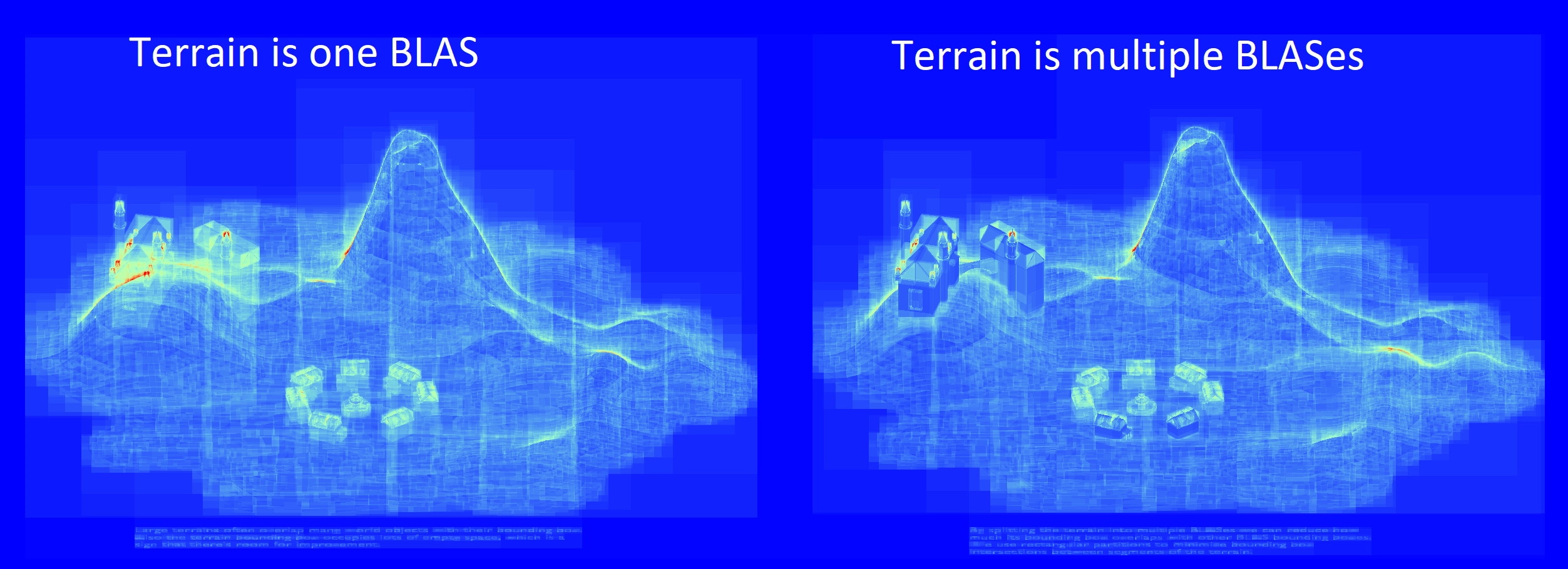
In particular, notice how the castle and the two nearest houses are much darker (indicating lower traversal cost) when the terrain is split up into chunks.
The reason the two front houses benefit more than the other houses is a function of how the driver decided to build the TLAS. This is outside the direct control of the developer, but by reducing instance overlap this gives the driver opportunity to make more optimal acceleration structures.
At its core, this example is the same as the last one: try to avoid instance overlap. But the following is a more general way of diagnosing this in RRA.
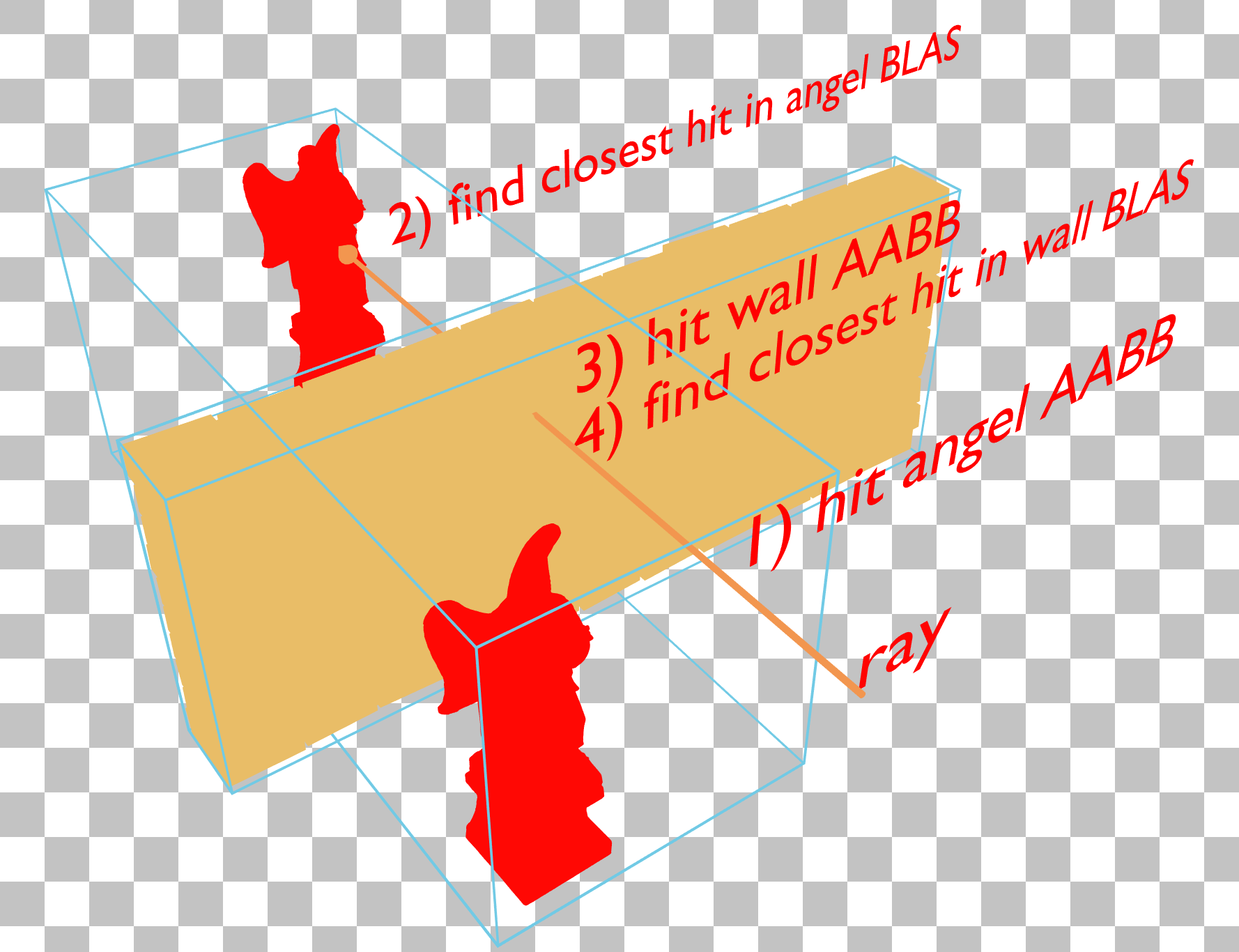
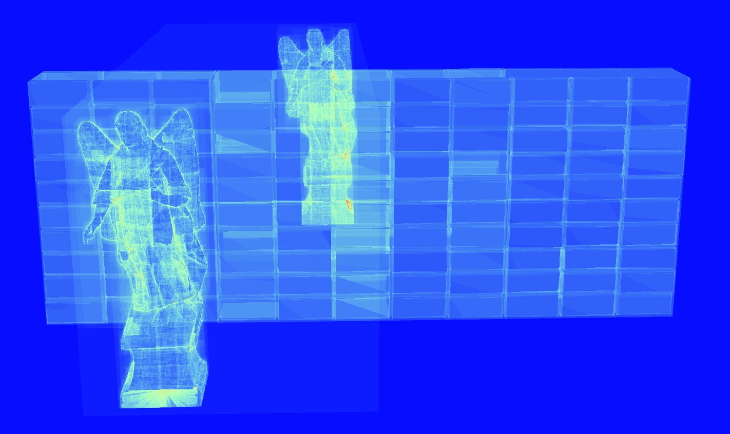
This X-ray effect where the further angel statue is visible through the wall in traversal counter mode is something to avoid. This indicates that the cost of traversal for the further angel is being incurred even though most of it is occluded by a wall.
In this example, both angel statues are in the same BLAS, so the blue bounding volumes of the angels and wall are intersecting, resulting in the ray first traversing the angel’s BLAS before traversing and being terminated by the wall’s BLAS.
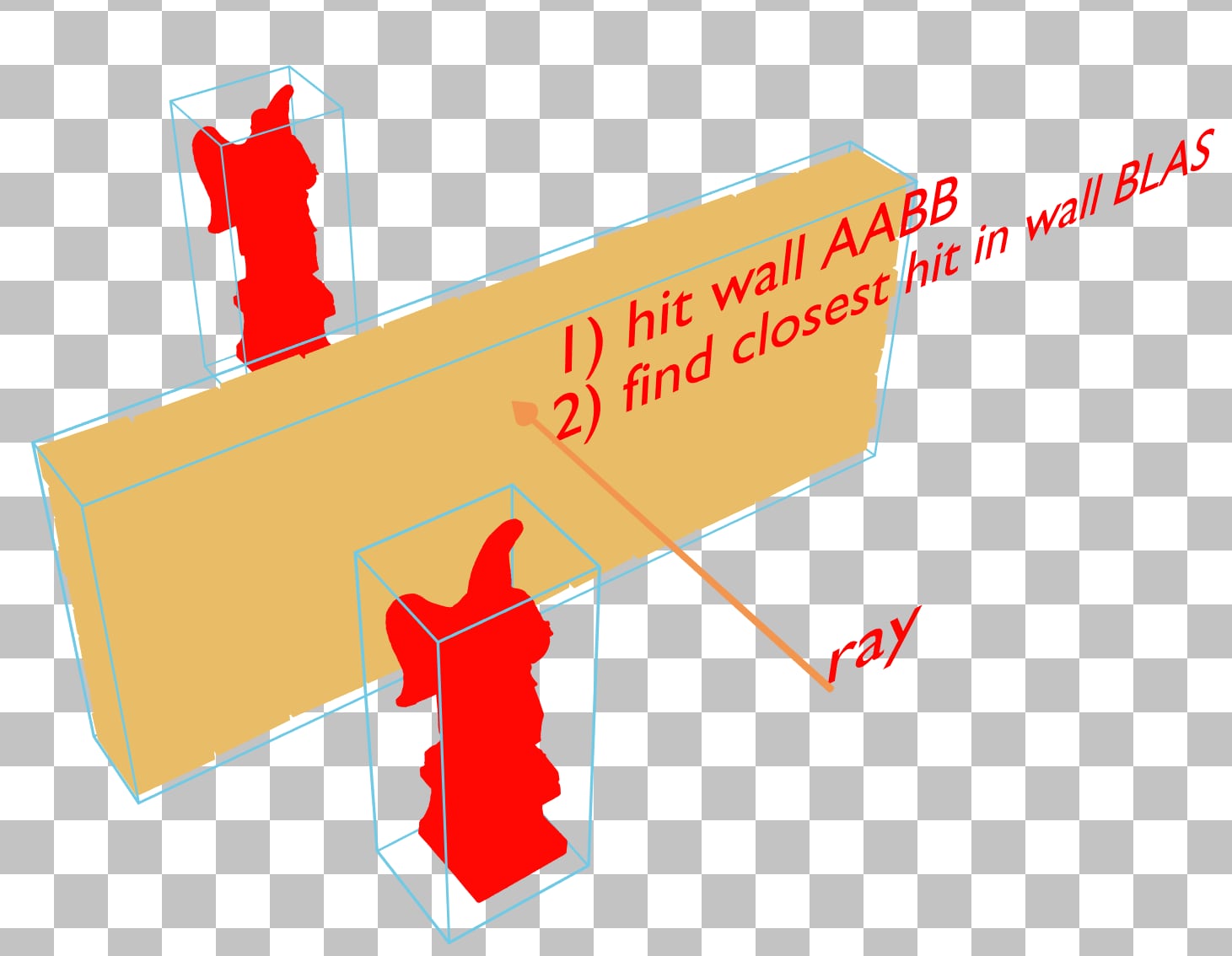
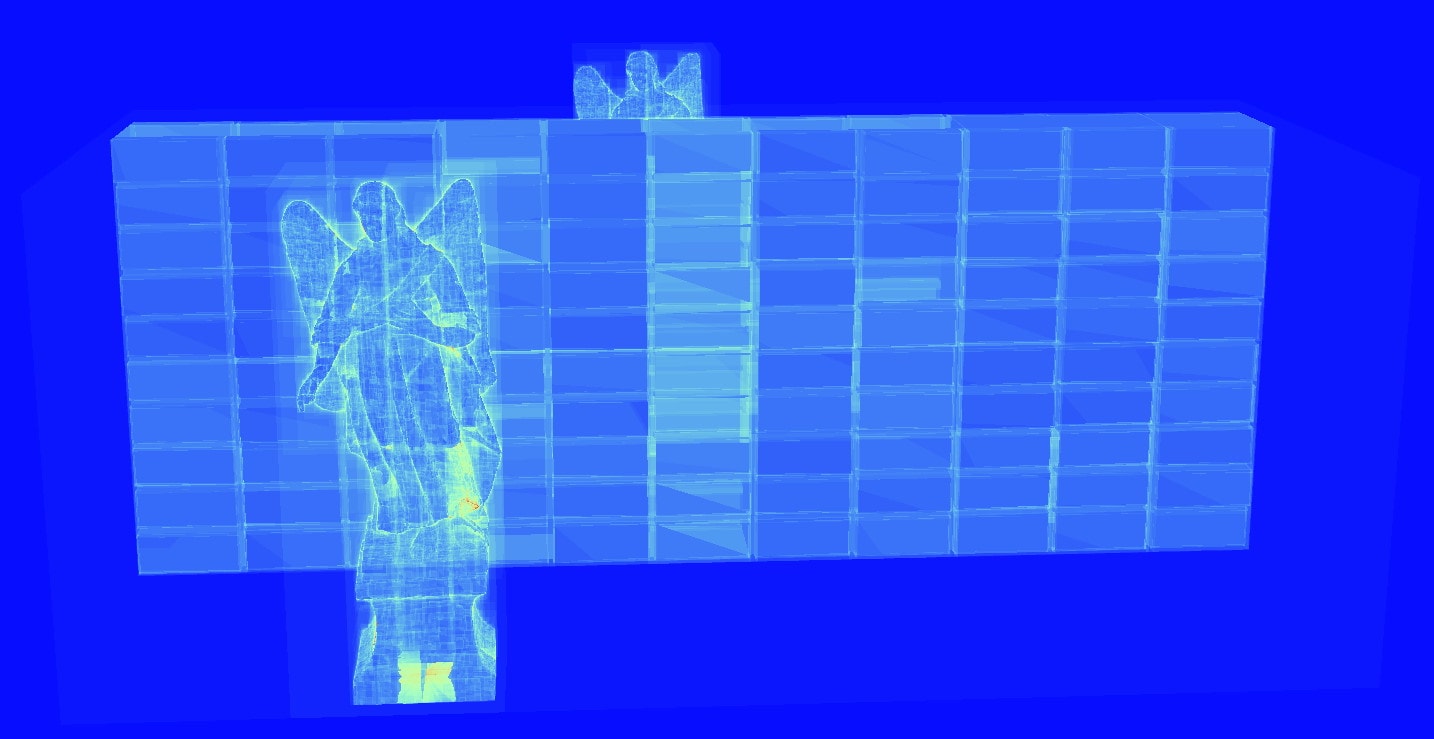
By changing the angel BLAS to contain only one angel and instancing it twice, the angel’s bounding volumes no longer intersect with the wall’s. This gives the driver the opportunity to construct a TLAS which can terminate traversal sooner without needing to traverse through the further angel’s BLAS. Keep in mind that even after reducing instance overlap it’s possible that the X-ray effect persists depending on how the driver builds the acceleration structure, but by minimizing overlap it’s expected that the TLAS quality will be higher overall.
In the rasterization pipeline, the orientation of triangle meshes in their local space has no effect on performance. This is not true in the ray tracing pipeline.
Currently, BVH building methods use hierarchies of axis aligned bounding boxes for the ray to traverse. The less aligned triangles are with the coordinate axes (x, y, and z axes) the larger their bounding volumes will be, which increases the probability of a ray intersecting the bounding volume but missing the triangle. This results in a higher traversal count to find the closest hit since more boxes are intersected.
To measure how well axis aligned a triangle is in RRA, a surface area heuristic (SAH) is used, which is a number between 0 and 1 that’s proportional to the probability that a triangle is intersected by a ray, given the ray intersecting its bounding volume. So 0 is bad and means it’s improbable the triangle is intersected and 1 is good and means it’s probable the triangle will be intersected.
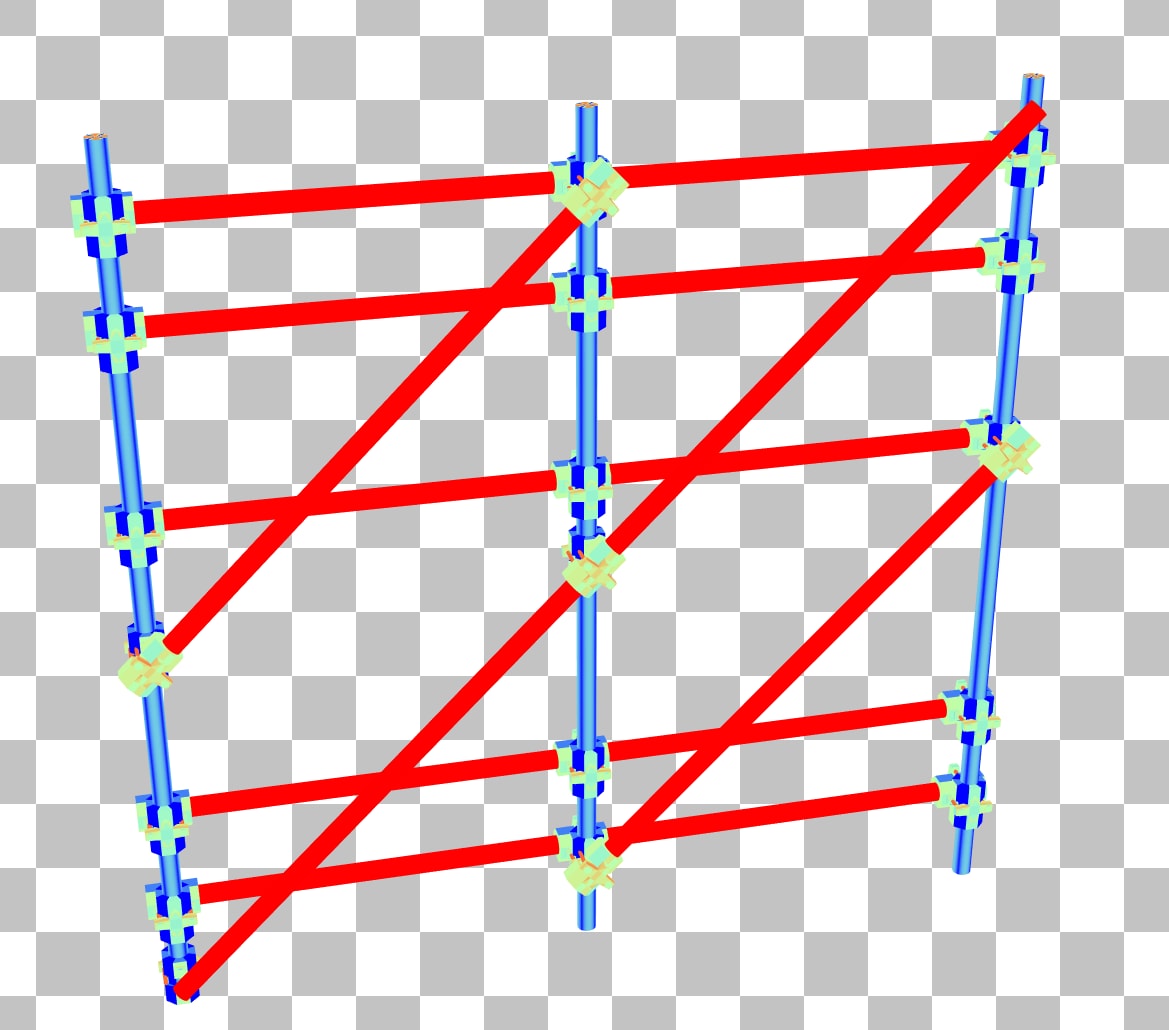
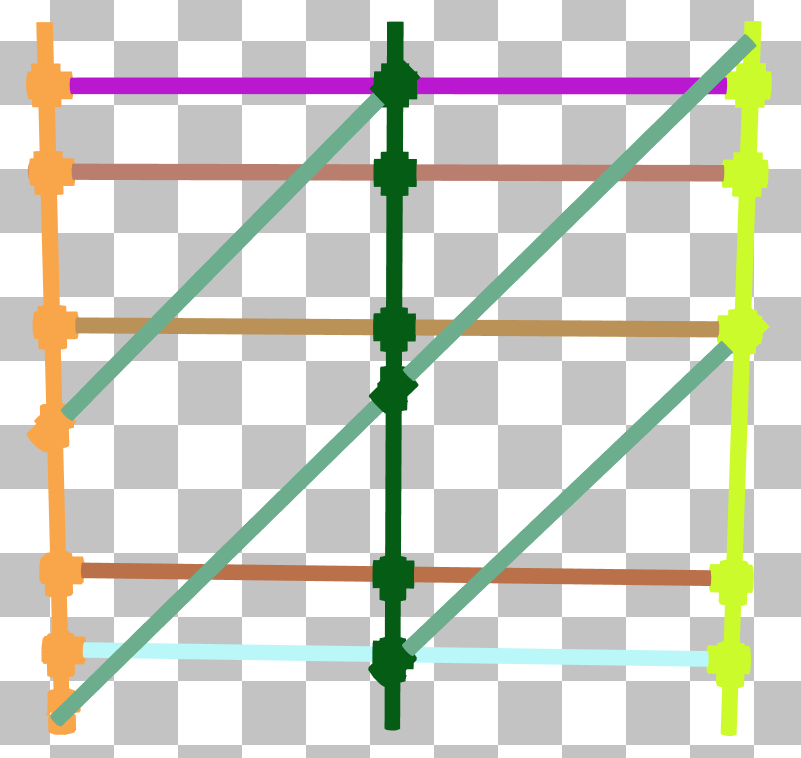
In the triangle SAH coloring mode, many of the poles in this scaffolding are bright red, indicating that the SAH is very low. This is a major indicator that the BLAS can be better aligned in local space.
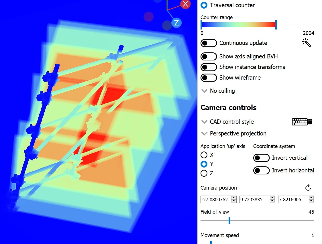
Switching to traversal counter mode, the scaffolding is producing traversal counts greater than 2000, and will likely cause a noticeable drop in the framerate when it’s on screen in your application.
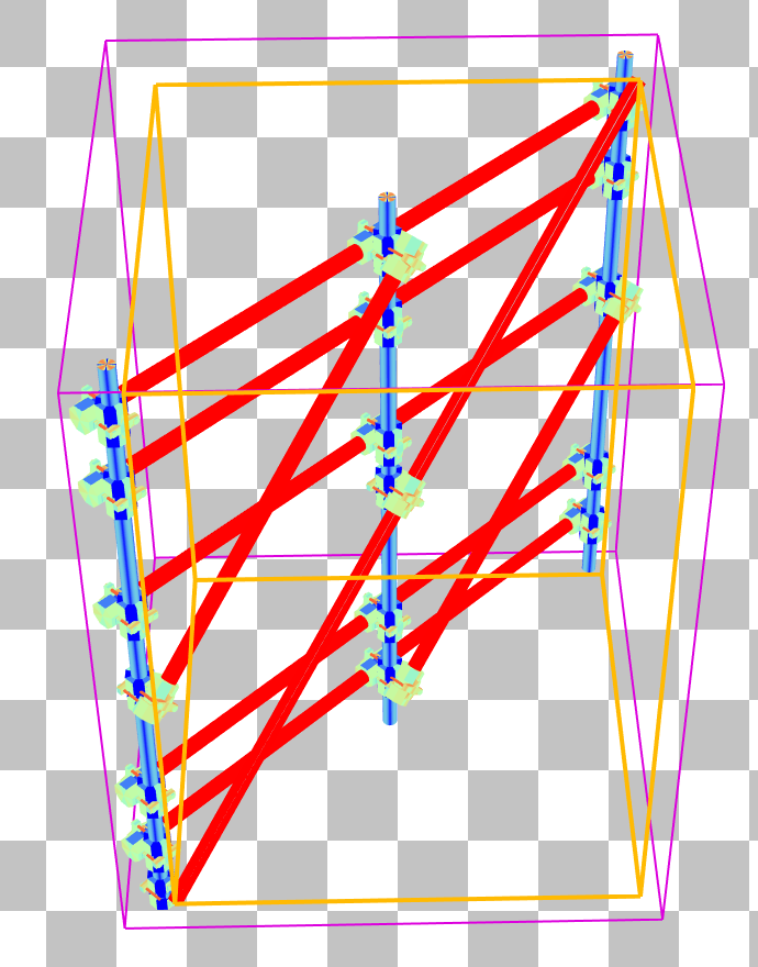
Double clicking the scaffolding will bring us to the BLAS pane which reveals the scaffolding is rotated 45 degrees from being aligned with the x-axis. Selecting one of the triangles on a diagonal pole shows that its bounding box is unnecessarily large, covering nearly the whole BLAS.
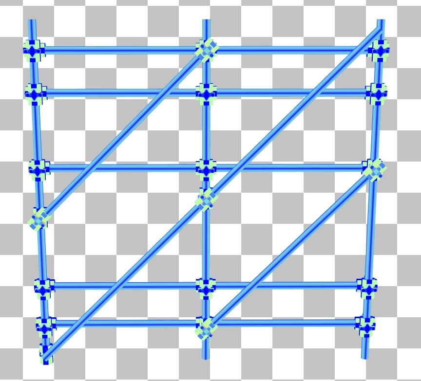
This can easily be improved by rotating the scaffolding mesh in BLAS space by 45 degrees so that the horizontal poles are aligned with the x-axis. This results in the following BLAS:
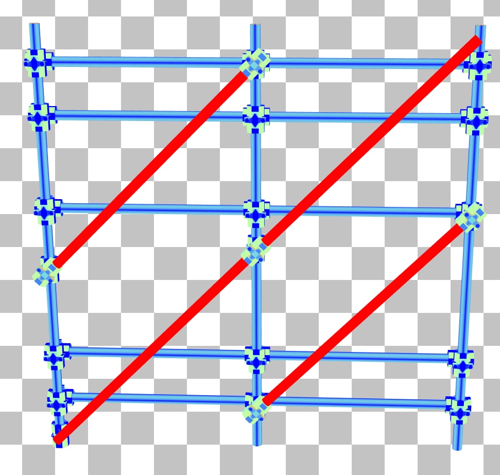
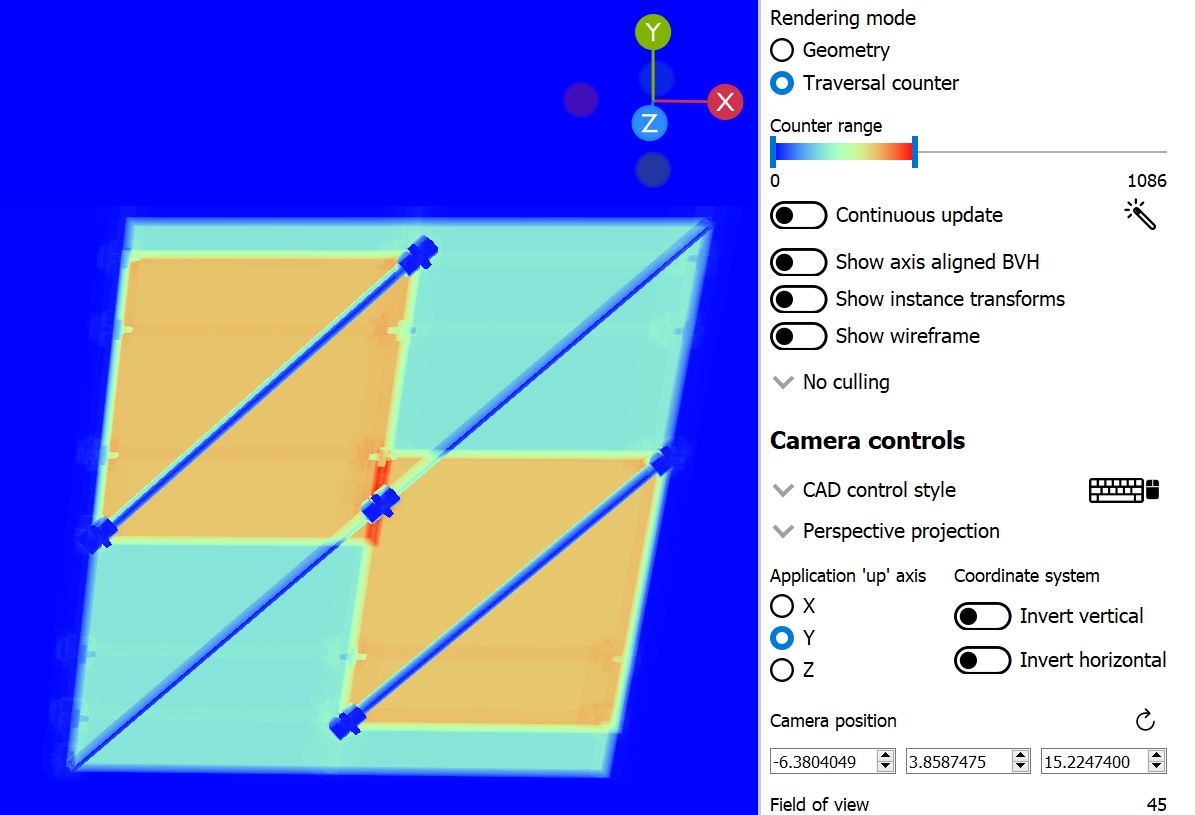
The vertical bars now have a much better SAH and the traversal counter has dropped significantly to about 1000 iterations. There is no tradeoff to this adjustment; it is purely beneficial.
But the diagonal bars are still problematic and are to blame for most of the traversal time spent on this BLAS. By separating the scaffolding into multiple BLASes, axis aligning each in local space, then using their instance transform to place them back in their original formation, it yields the following result:
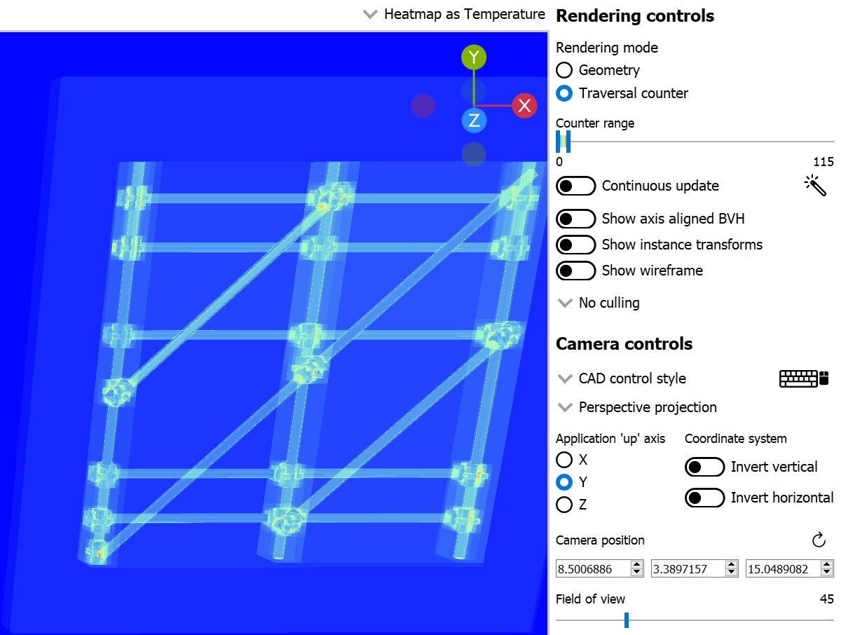
The unique instance coloring mode (left) shows how the scaffolding was split into multiple BLASes and instanced. The SAH coloring mode (middle) indicates there are no longer any problematic triangles, and the traversal count (right) drops by a whole order of magnitude. Please use caution if you decide to follow this route, since creating more instances will result in a longer TLAS build time. Always profile to see if this trade-off makes sense for your project. Also, splitting a BLAS into multiple BLASes often results in overlapping instances, which we’ll see in the next example can sometimes make the traversal cost even worse, despite having better SAH.
In the last example, there is a scenario where splitting a BLAS into multiple constituent BLASes could reduce traversal cost by axis aligning each individual BLAS in local space. Use caution and profiling to decide whether to go down this route. Aside from the longer TLAS build time, this can actually harm traversal time as well even when the SAH improves.
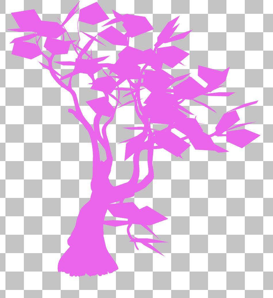
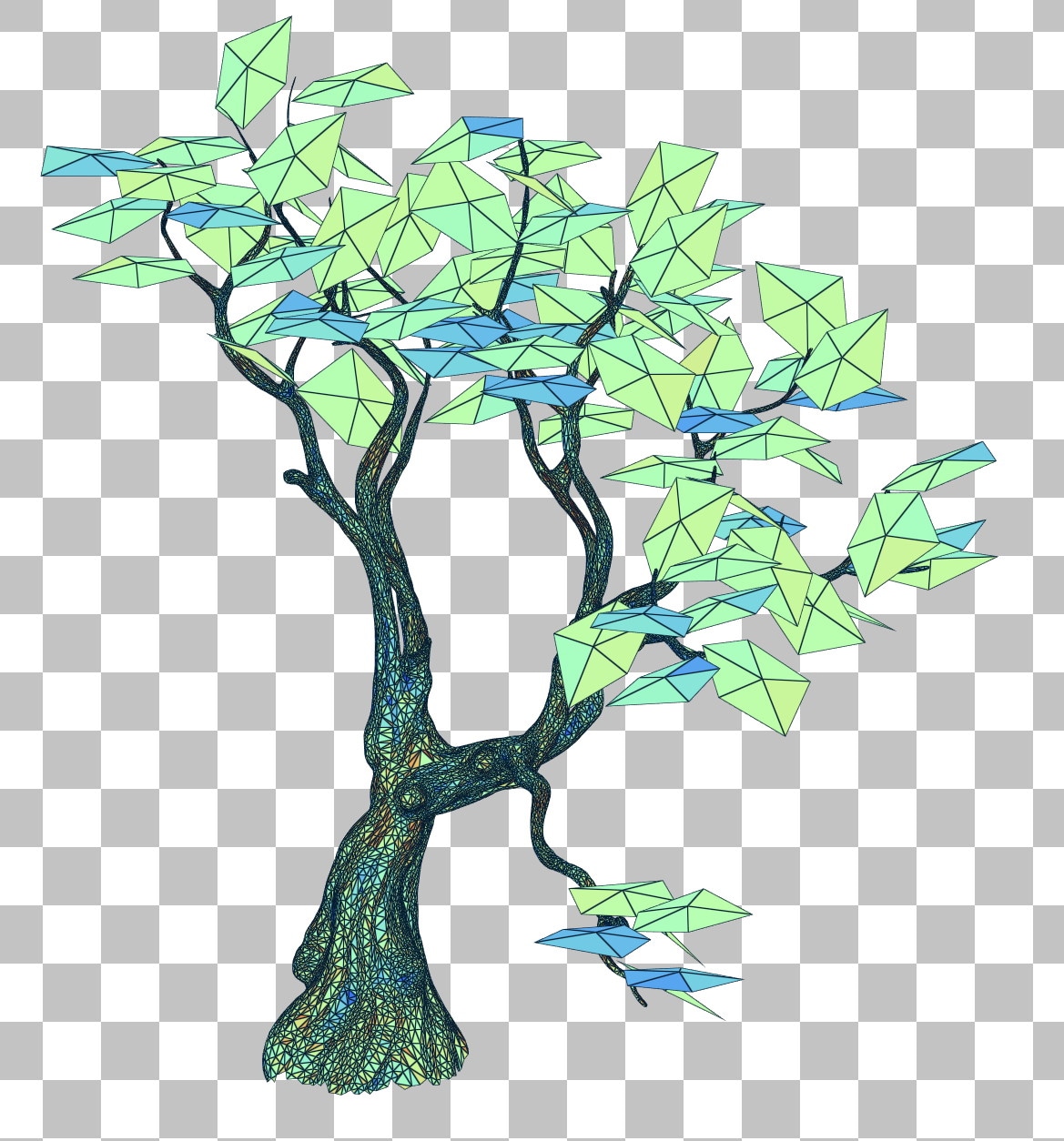
Consider the tree above, which is a single BLAS. The leaves are oriented in all directions and do not line up well with the axes in local space, so it may be tempting to split the leaves into several BLASes based on their orientation in order to lower their SAH.
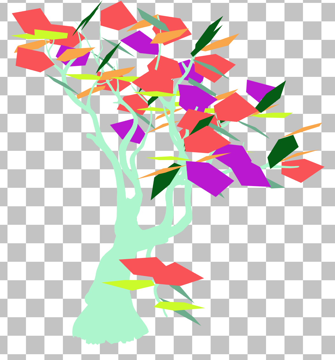
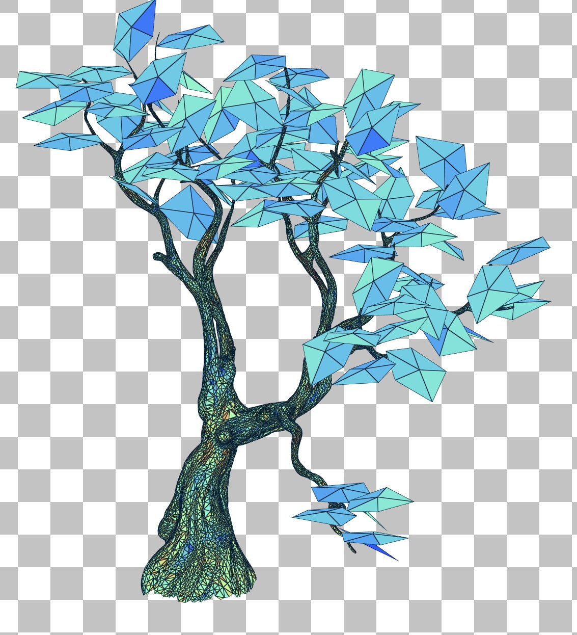
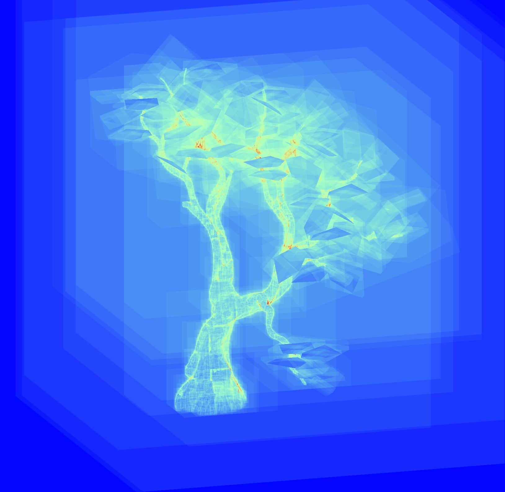
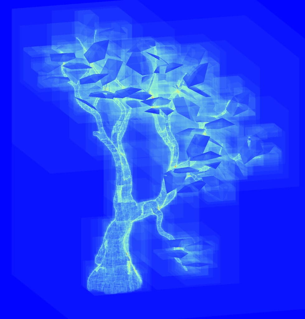
The unique instance coloring mode (left images) reveals all the instances used to construct each tree. After splitting the leaves into 6 separate BLASes grouping them together based on orientation and rotating in local space, the SAH (middle images) of the leaves has been lowered but the traversal count (right images) has gotten worse from all the overlapping instances, and the TLAS build time is also negatively affected by having more instances.
A common mistake is to split a mesh into multiple BLASes, maybe one for each material.
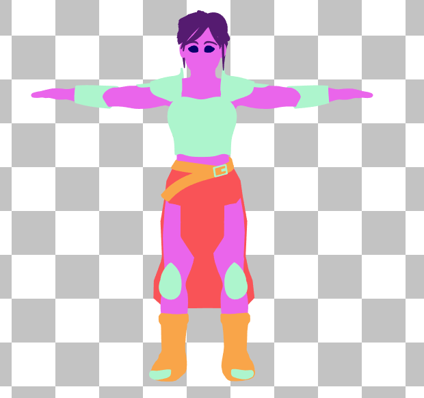
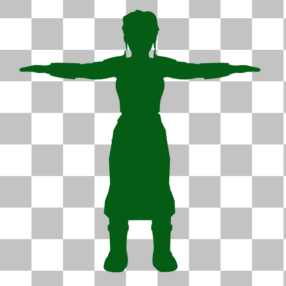
The unique instance coloring mode shows the mesh split up into one BLAS per material (left) and the mesh contained in a single BLAS (right).
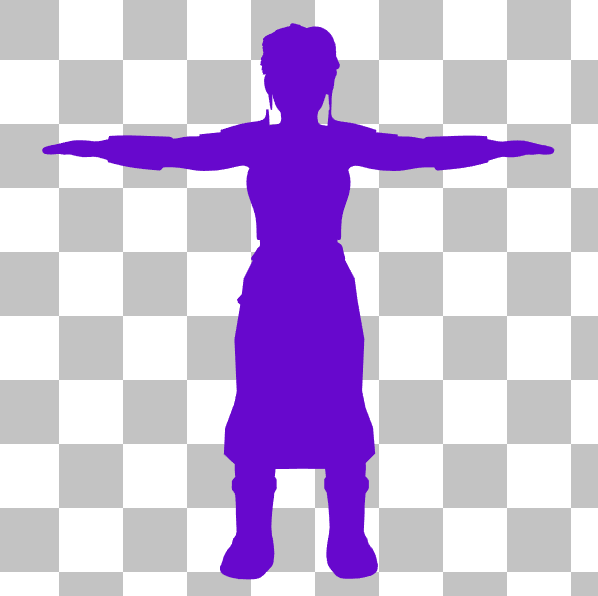
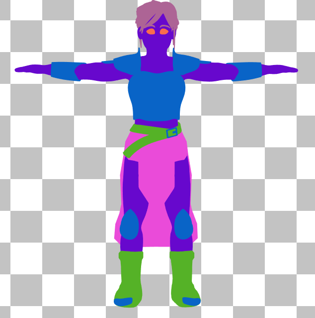
The geometry index coloring mode shows that the multiple BLAS version (left) is not using multiple geometry indices, whereas the single BLAS version (right) has one geometry index per material.
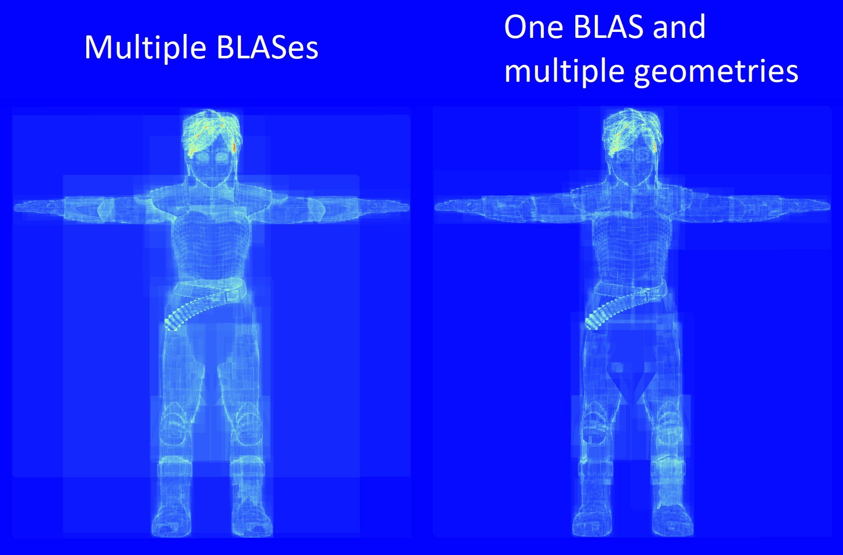
Switching to traversal counter rendering mode, it is apparent that using multiple geometries in a BLAS has a lower traversal cost than the multiple BLAS version, since that one results in significant instance overlap. There is the added benefit that using fewer instances positively impacts TLAS build time.
Instance transforms that significantly stretch or skew the underlying BLAS are often not optimal since BLASes are built relative to the non-deformed mesh.
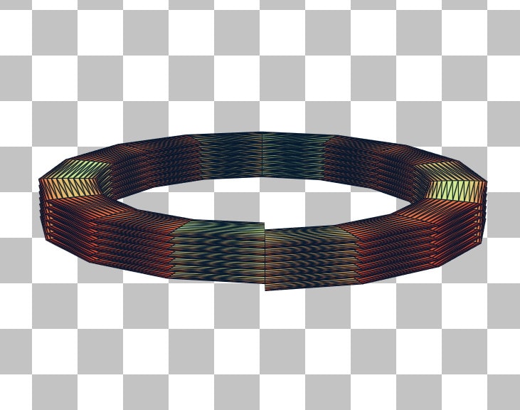
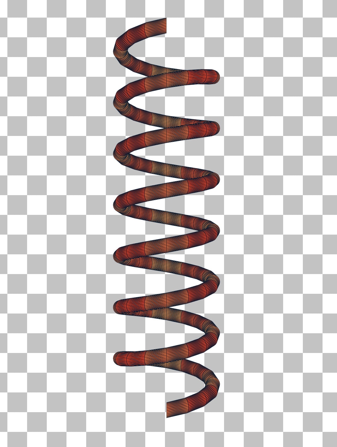
Here are two BLASes in local space. They are the same mesh except the one on the left is scaled down on the y-axis.
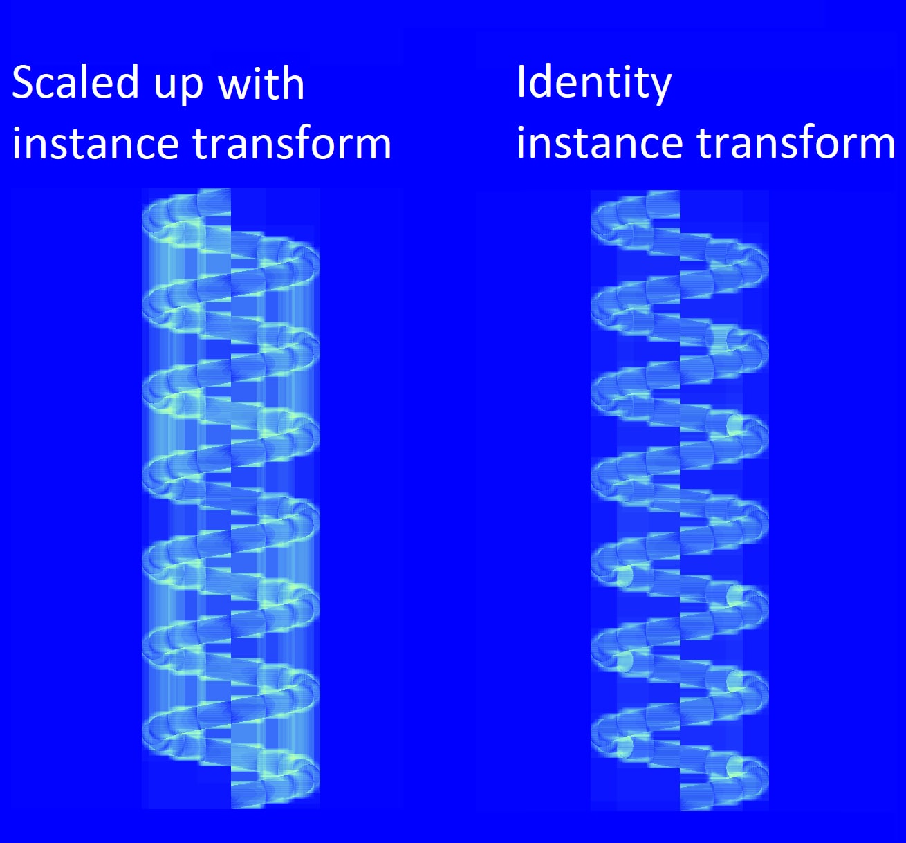
In global space the left spring is scaled up on the y-axis using the instance transform to compensate for it being scaled down in local space, so both springs appear identical. But the spring with the identity instance transform has a better traversal count since its BLAS was built relative to this transformation.
In the rasterization pipeline, frontface and backface culling are an optimization. In the ray tracing pipeline, enabling either of these will hurt ray traversal performance, because any triangle that’s culled still needs to be tested against. It just will not be considered a candidate for the closest hit, so the traversal algorithm will not terminate as soon as it would without culling.
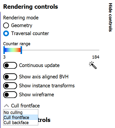
In geometry rendering mode, the culling dropdown just affects the viewport renderer and does not reflect the application that was captured. In traversal rendering mode, on the other hand, the culling mode plays the part of the frontface/backface culling flags passed to the trace ray call in the shader. This means that the culling behavior can be overridden or modified for each instance via instance flags. By selecting frontface culling, the difference in traversal cost becomes apparent between the instances.
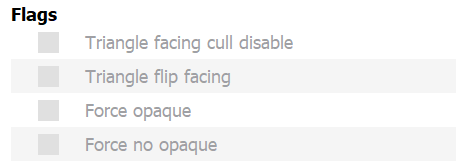
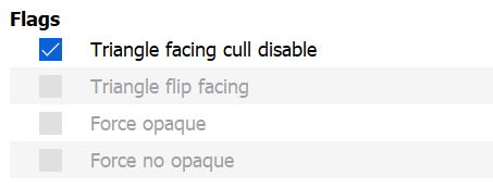
There are two instances, one of which has the “triangle facing cull disable” flag enabled. This flag takes precedence over the trace ray flag (or the cull mode dropdown, in this case).
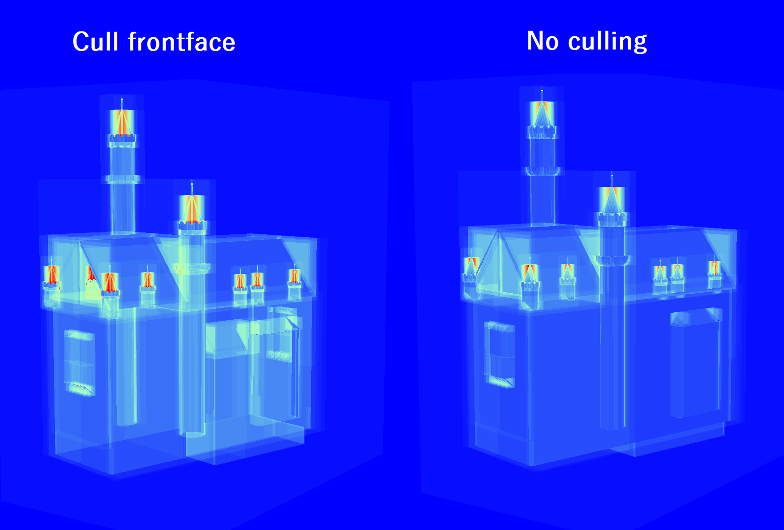
Switching to traversal counter rendering mode shows that the instance with culling disabled has a lower traversal cost.
When disabling ray tracing features that aren’t needed, like face culling, it is better to use compile-time ray flags to disable them. This allows the compiler to optimize the shaders. For example, it is better to not pass the RAY_FLAG_CULL_BACK_FACING_TRIANGLES flag to TraceRay() in HLSL, than to pass the flag and disable culling via instance flags. Likewise, passing RAY_FLAG_FORCE_OPAQUE TraceRay() allows the compiler to optimize more than just enabling the “force opaque” instance flags on each instance. Forcing opaque has the benefit that it eliminates calls to AnyHit shaders which are expensive.
When constructing BLASes, DirectX 12 and Vulkan allow you to either build one from scratch or to use a similar existing source BLAS to construct the new destination BLAS. Using update mode can result in faster BLAS build times since it can reuse portions of the source BLAS.
A common usecase is in character animation or mesh deformations, since the BLASes from one frame to the next vary only slightly. Consider the case of animating a bow being drawn.
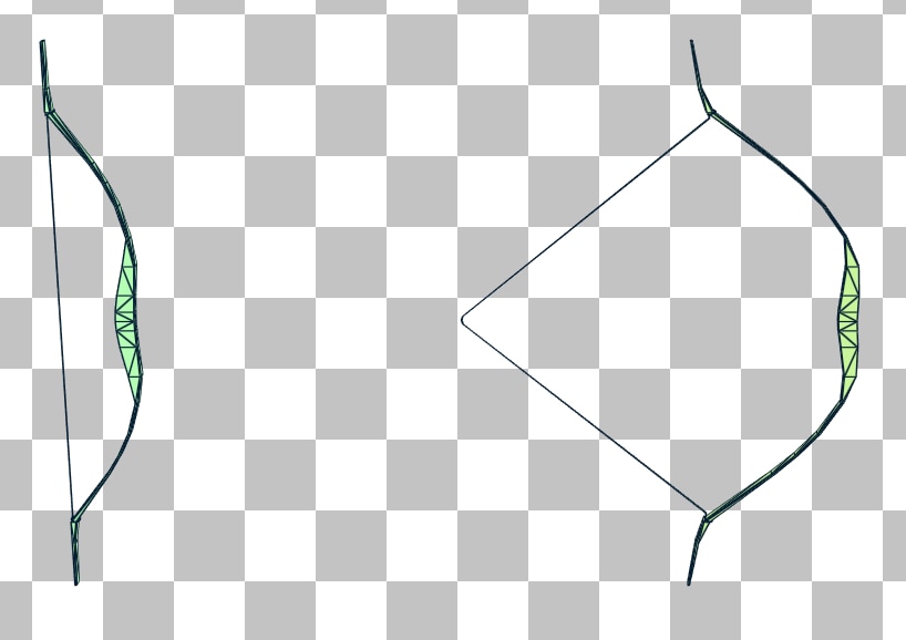
Now let’s compare the BVH quality when the drawn bow is constructed using build mode vs constructing it with update mode with the undrawn bow as the source.
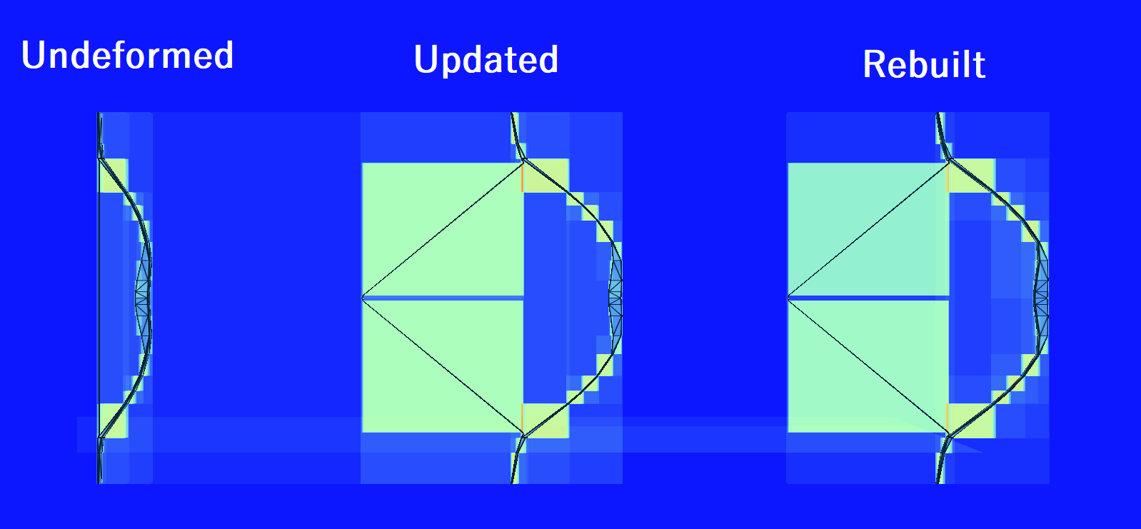
Traversal counter mode shows that there is not a significant difference in the time it takes rays to traverse the updated vs rebuilt BLASes, but with the updated one, time is saved at build time.
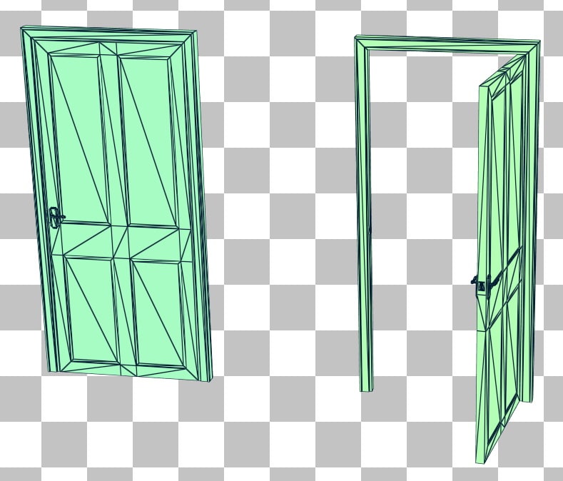
Now consider animating a door being opened.
Once again we’ll compare the BVH quality between the updated and rebuilt BLASes.
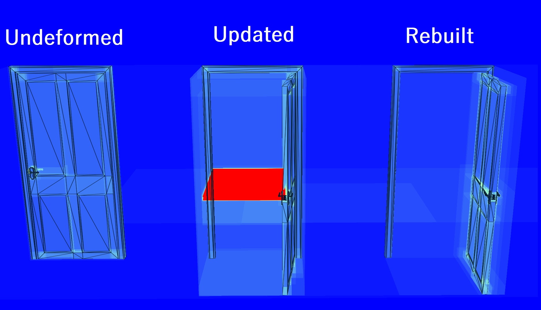
What went wrong? There’s a big section of the updated BLAS that consumes about 1100 traversal steps. Why the dramatic difference between the bow and door?
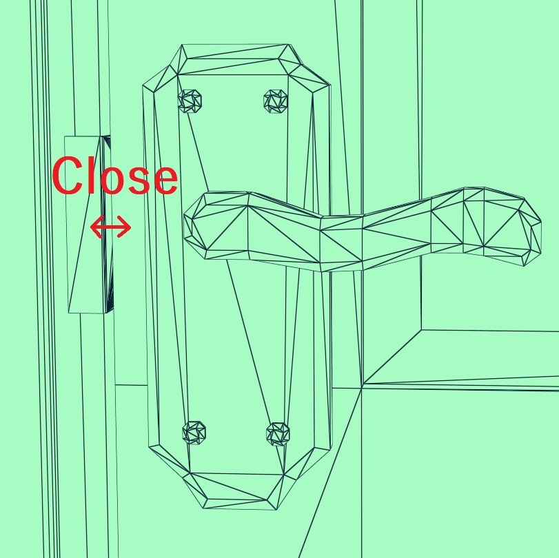
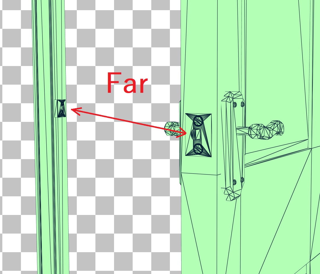
In the undeformed source BLAS, the door latch and strike (metal piece screwed to the frame) have a lot of triangles that are very close to one another, but in the deformed destination BLAS these triangles become far apart since the door is open. Triangles starting close and ending far apart are bad candidates for using update mode since it results in suboptimal BVHs like this.
The good candidates for being updated have the property that triangles that are close together in the undeformed state stay close together in the deformed state. In practice, this will be smooth deformations like the stretching of a bow or the bending of an arm, but not deformations where triangles are torn apart, like the latch of a door or a cloth tearing.
One possible solution is to rebuild every n frames and update all the other frames. This could help avoid getting BVHs that are too sub-optimal while not needing to pay the cost of rebuilding every frame.
This example doesn’t use RRA but it’s important enough that it still deserves to be mentioned. Consider the following scene of reflective spheres.
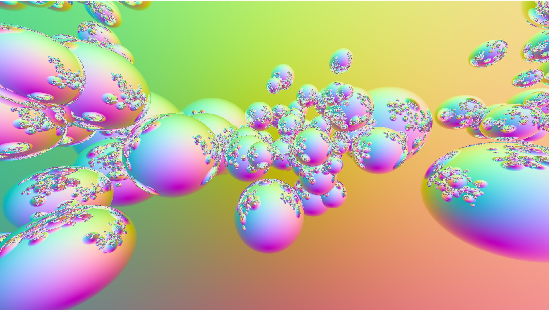
This is ray traced with 16 bounces. In the ray tracing shaders, it can be implemented either recursively or iteratively.
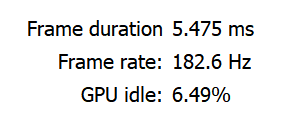
In the recursive case, the raygen shader casts one ray per pixel, and the rays that intersect with a sphere will trigger a closest-hit shader which will in turn cast another ray. The example uses the following payload:
struct Payload { vec4 color; int depth; /* Stack depth needed to terminate recursion. */};The number of bounces is tracked in the payload so that the recursion can terminate once 16 bounces have occurred. That’s a common way to do things for offline rendering, but is usually far too expensive for real-time games. Profiling in RGP at 1080p on a Radeon RX 6700 XT resulted in the following:
For the iterative implementation, all of the rays are cast from the raygen shader in a for-loop. You should disable recursion completely by setting D3D12_RAYTRACING_PIPELINE_CONFIG::MaxTraceRecursionDepth = 1 in DirectX 12 and VkRayTracingPipelineCreateInfoKHR::maxPipelineRayRecursionDepth = 1 in Vulkan. Remove the depth member of the payload which kept track of the recursion depth, and replace it with origin , direction , and missed members.
struct Payload { vec4 color; vec3 origin; /* Ray origin of the next ray to be cast. */ vec3 direction; /* Ray direction of the next ray to be cast. */ bool missed; /* Whether the ray invoked the miss shader. */};The origin and direction are set by the closest-hit shaders instead of casting the ray themselves. When control returns to the raygen shader, it uses these members to cast another ray. The missed member is set to true by the miss shader whenever it’s invoked, which lets the raygen shader break out of the loop early when the ray has terminated. In GLSL, the raygen shader looks like the following.
primary_payload.color = vec4(0.0, 0.0, 0.0, 1.0);primary_payload.origin = camera.origin.xyz;primary_payload.direction = direction;primary_payload.missed = false;
for (int i = 0; i < 16; ++i){    traceRayEXT(        TLASES[0],                 /* topLevel */        gl_RayFlagsNoneEXT,        /* rayFlags */        0xFF,                      /* cullMask */        0,                         /* sbtRecordOffset */        0,                         /* sbtRecordStride */        0,                         /* missIndex */        primary_payload.origin,    /* origin */        0.01,                      /* Tmin */        primary_payload.direction, /* direction */        1.0 / 0.0,                 /* Tmax */        0                          /* payload */    );
    if (primary_payload.missed)    {        break;    }}
In this example, the rays which bounce 16 times without invoking the miss shader will keep their default color of black. Profiling with RGP resulted in:
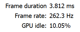
The iterative approach only took 69.6% of the time of the recursive approach[1], and the GPU idle percentage has gone up, which means the GPU can be more free to do other work we submit to it.
Separate packages for Linux and Windows are available for download. More detailed information on RMV can be found in the online documentation.
Download Radeon Developer Tool Suite (Windows®) Download Radeon Developer Tool Suite (Linux)[1] Tested with an AMD Ryzen 7 5800X 8-Core Processor, 64 GB RAM, and Radeon RX 6700 XT at 1080p with one primary ray per pixel.
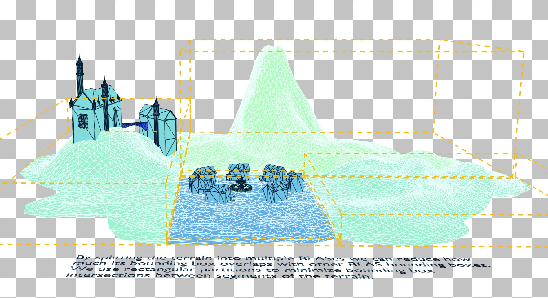
Splitting the terrain into chunks can greatly reduce the overlap with the bounding boxes of the other instances, and the bounding volumes also now have a tighter fit around the terrain. The trade-off here is that more instances means a longer TLAS build time, but for something like terrain that affects the traversal time of a majority of frames in the game, this is usually an acceptable tradeoff. It’s still recommended to use Radeon GPU Profiler to profile the TLAS build time to ensure it is acceptable.
The benefit in ray traversal time can be made clearer by switching to the traversal counter rendering mode in RRA.
© 2022 Advanced Micro Devices, Inc. All rights reserved.
The information presented in this document is for informational purposes only and may contain technical inaccuracies, omissions, and typographical errors. The information contained herein is subject to change and may be rendered inaccurate for many reasons, including but not limited to product and roadmap changes, component and motherboard version changes, new model and/or product releases, product differences between differing manufacturers, software changes, BIOS flashes, firmware upgrades, or the like. Any computer system has risks of security vulnerabilities that cannot be completely prevented or mitigated. AMD assumes no obligation to update or otherwise correct or revise this information. However, AMD reserves the right to revise this information and to make changes from time to time to the content hereof without obligation of AMD to notify any person of such revisions or changes. THIS INFORMATION IS PROVIDED ‘AS IS.” AMD MAKES NO REPRESENTATIONS OR WARRANTIES WITH RESPECT TO THE CONTENTS HEREOF AND ASSUMES NO RESPONSIBILITY FOR ANY INACCURACIES, ERRORS, OR OMISSIONS THAT MAY APPEAR IN THIS INFORMATION. AMD SPECIFICALLY DISCLAIMS ANY IMPLIED WARRANTIES OF NON-INFRINGEMENT, MERCHANTABILITY, OR FITNESS FOR ANY PARTICULAR PURPOSE. IN NO EVENT WILL AMD BE LIABLE TO ANY PERSON FOR ANY RELIANCE, DIRECT, INDIRECT, SPECIAL, OR OTHER CONSEQUENTIAL DAMAGES ARISING FROM THE USE OF ANY INFORMATION CONTAINED HEREIN, EVEN IF AMD IS EXPRESSLY ADVISED OF THE POSSIBILITY OF SUCH DAMAGES.
AMD, the AMD Arrow logo, and combinations thereof are trademarks of Advanced Micro Devices, Inc. Other product names used in this publication are for identification purposes only and may be trademarks of their respective companies.