Vulkan® Memory Allocator
VMA is our single-header, MIT-licensed, C++ library for easily and efficiently managing memory allocation for your Vulkan® games and applications.
Dense Geometry Format (DGF) is an exciting new technology from AMD which we’ve written about several times. If you’re not familiar with AMD DGF, we encourage you to read our previous posts (here, and here, the technical paper here, and our latest blog about our partnership with Samsung to develop a multivendor DGF extension for Vulkan®.
We’ve recently released an update to the AMD DGF SDK with a few new goodies. For a complete list, refer to the v1.2 release notes here. This blog post will focus on a new feature called DGF SuperCompression (DGFS), which we’re particularly excited about.
The current API design for ray tracing acceleration structures is a “black box” in which a neutral input format is translated by the driver into a hardware-specific format. This provided considerable flexibility for implementations. It was a necessary step in the API evolution, but it has certain fundamental limitations:
Software developers have expressed interest in creating a standard efficient geometry compression format to address these limitations. DGF fills this role — performing for geometry compression what formats like DXT, ETC, and ASTC have done for texture compression.
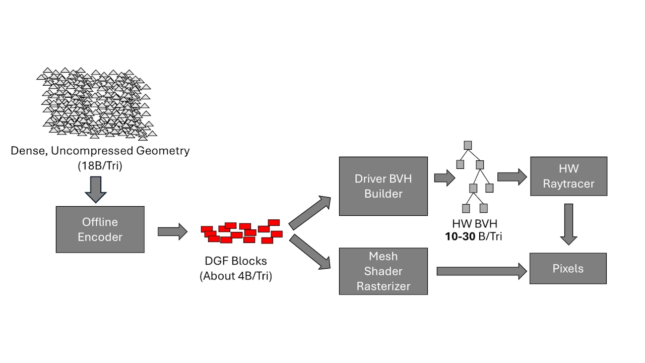
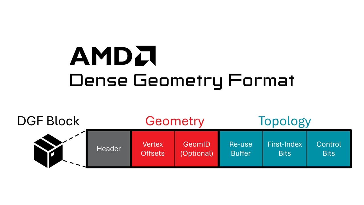
DGF was designed first and foremost as an efficient hardware format. Its design ensures that all of the information required for a particular triangle can be accessed using a single 128B aligned memory read. This property, although essential for efficient hardware ray traversal, has consequences which make it less appealing as a storage format. Vertex positions and compression parameters need to be duplicated across multiple blocks, and pad bits need to be inserted for data alignment, especially if blocks are not full.
We address this by introducing DGF SuperCompression (DGFS), a software system which further compresses DGF data to reduce its storage cost. Geometry encoded with DGFS is no longer directly consumable by hardware, but can be made considerably smaller. DGFS is able to exactly reconstruct a given set of input DGF blocks, and also supports efficient decode to a conventional vertex and index buffer, which enables DGFS content to run on non-DGF hardware.
Returning to the texture compression analogy: DGFS does for DGF what Basis Universal™ does for DXT.
Adopting DGFS for asset packages has two key advantages over storing DGF blocks directly:
Rendering engines are increasingly being architected around small, self-contained clusters of triangles. These clusters (also known as “Meshlets”), are used to construct GPU Driven Rendering Pipelines, or fine-grained level of detail systems. Triangle clusters are a logical unit of work for culling, animation, LOD, and geometry streaming. For this reason, we use a cluster-granular compression system for DGFS, in which each triangle cluster is compressed and decoded independently.
Some observers have described DGF as a “response” to the development of cluster-level acceleration structures (CLAS). It is easy to see where this misconception comes from, but it’s not accurate. DGF is not a response to the development of cluster-level acceleration structures (CLAS), but an orthogonal, complementary technology. A BLAS can be built out of arrays of vertex and index data, or an array of DGF blocks. A CLAS, likewise, can be built out of much smaller arrays of the same things. Pre-compressed geometry can be applied in both cases with the same benefits.
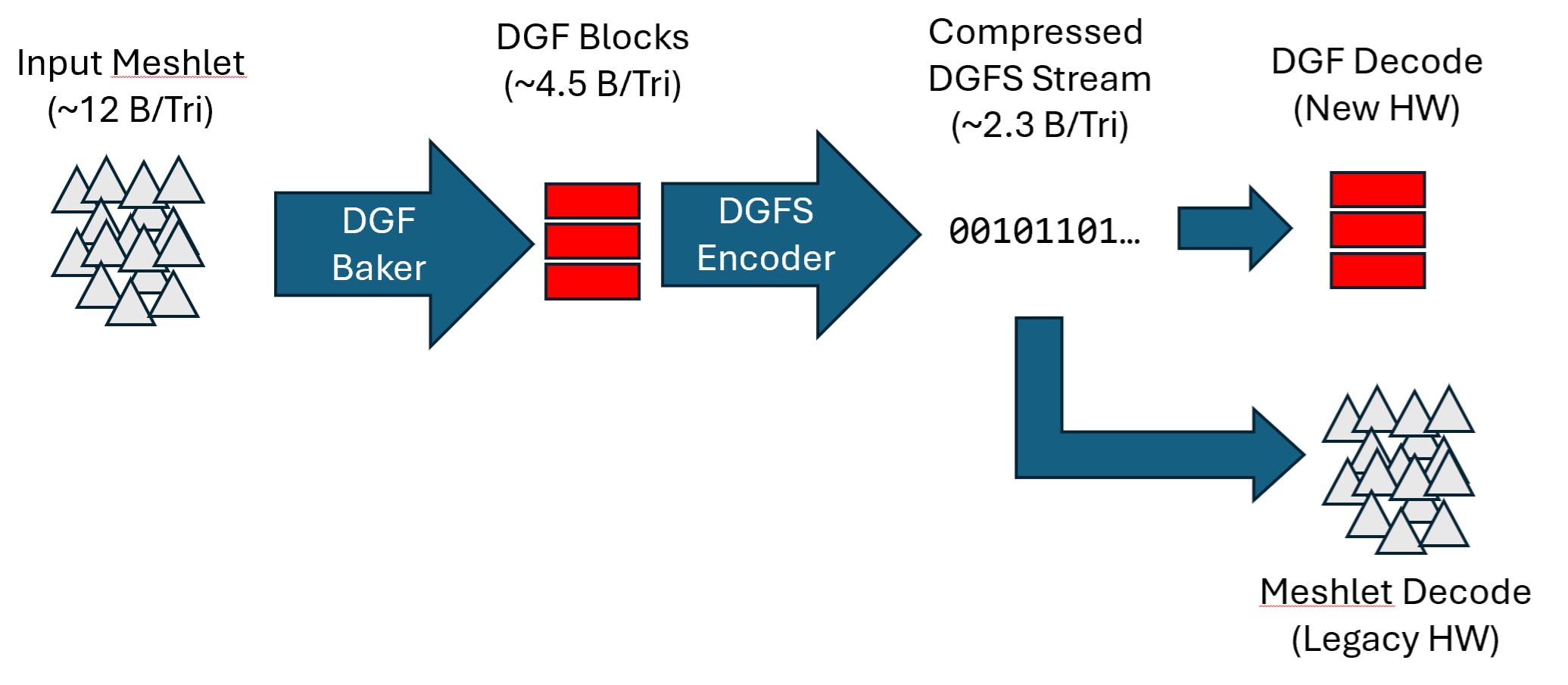
The DGFS stream is designed in such a way that it can be easily decoded to an indexed mesh OR an array of DGF blocks, as illustrated below. With DGFS, an application is effectively storing two geometry representations for the price of one, which enables a title to easily target DGF and non-DGF devices with a common storage format.
A DGFS byte stream is a variable-length compressed encoding of clusters of up to 256 unique vertices and triangles. The stream is built out of DGF blocks, and stores the minimal amount of information necessary to reconstruct the exact same set of blocks. Additional data transformations (zig-zag encoding, delta encoding, byte interleaving) are performed where appropriate, to improve compressibility when general-purpose compression is applied on top of the DGFS stream.
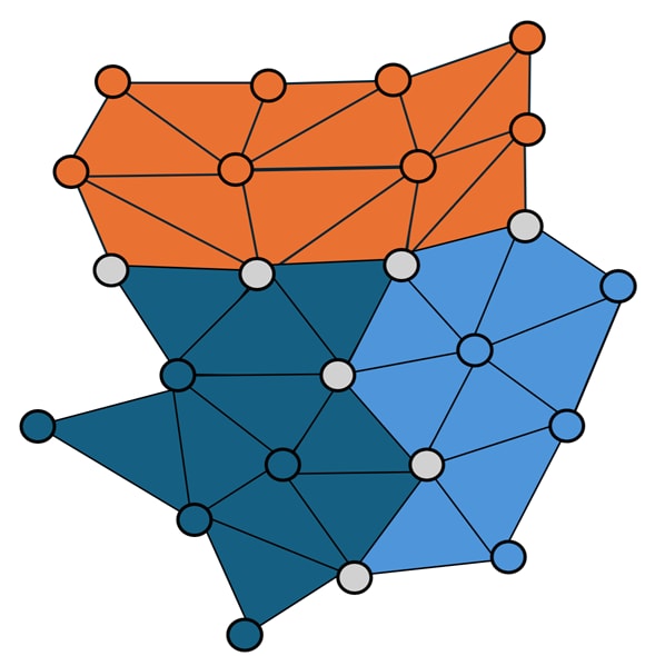
Duplicated vertices between blocks present a significant opportunity for super-compressing DGF data. The image below illustrates a triangle cluster decomposed into several DGF blocks, which are color coded. The grey vertices are located on block boundaries, and need to be stored in more than one block. There aren’t too many of these, but there are enough of them that it’s worth doing something about.
The DGFS encoder starts by decoding the block vertices and constructing a common encoding space (anchor, exponent, and offset size). We then convert all vertices into this common space, and eliminate the duplicates. The unique positions are then converted into deltas, zig-zag encoded, and stored in a byte-interleaved, struct-of-array form. We found that this layout improves the compression rate when general-purpose compression is applied on top of a DGFS stream.
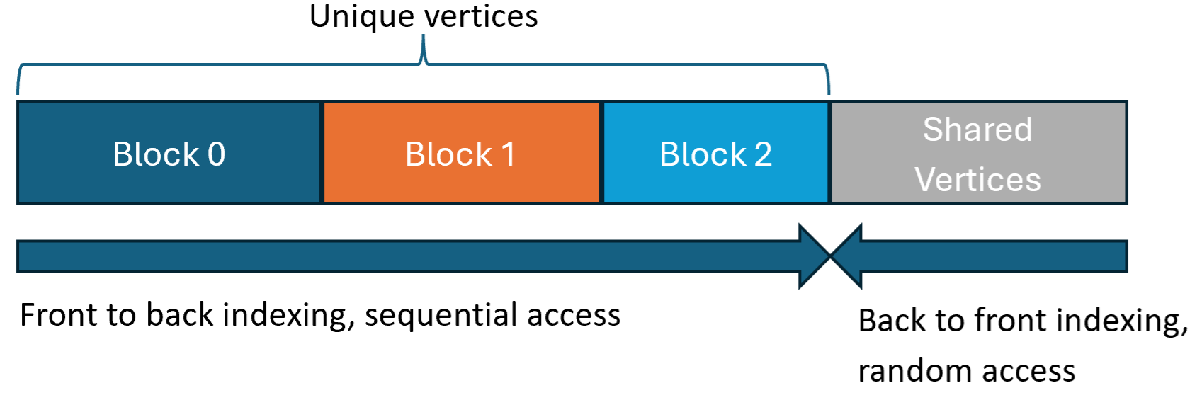
We arrange these vertices in a very particular order in the compressed stream. Unique vertices are indexed from the front of the vertex array, in order of their first occurrence in a block. Duplicated vertices are placed at the end, and indexed from the back. The reasons for this ordering will be explained next. The diagram below illustrates this layout for our three example blocks:
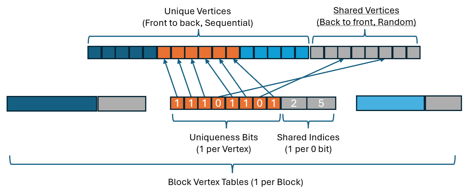
In order to reconstruct the original DGF blocks, we need to store a vertex table indicating which vertex position is present in each position within each block. There is one such table for each block. The ordering we use for the vertices allows us to make this table very small. We store a single bit per block vertex indicating whether it belongs to the “unique” or “shared” vertex sets. The index of each unique vertex can be computed by incrementing a running counter, and the indices of shared vertices can be directly stored. Indexing shared vertices from the back of the vertex array allows us to store smaller index values in the vertex tables. The diagram below illustrates the vertex table layout:
When decoding to DGF blocks, the vertex table is used to select vertices from the cluster vertex buffer to pack into a block. When decoding to a meshlet, it is used to convert block-level vertex indices into cluster-level indices to produce a meshlet with no duplicated positions.
We also apply de-duplication for the geometry IDs. Recall that a DGF block contains a GeomID Palette structure, where each triangle in the block stores a small selector from a set of unique geometry ID and flag values. In DGFS, the ID values are de-duplicated across blocks and stored using delta encoding and a variable byte length. The block-level structures are then modified to store indices into the corresponding cluster-level structures, which greatly reduces their size.
Because DGF already stores a very compact topology representation, we don’t attempt to compress it further, and simply embed the triangle control bits and compressed index buffer from each block directly into the DGFS stream.
The table below shows the raw storage footprints for a variety of models for both DGF blocks, and uncompressed DGFS streams. DGFS is roughly 30% smaller than DGF in its raw form:
| Crab | Dragon | Statuette | Buddha | Bike | |
|---|---|---|---|---|---|
| Triangles(Millions) | 2.14 | 7.22 | 10.00 | 1.09 | 1.68 |
| DGF Size (MB) | 10.22 | 29.25 | 40.99 | 4.94 | 6.96 |
| DGFS Size (MB) | 8.48 | 20.15 | 29.31 | 3.95 | 5.54 |
| Savings | 17.06% | 31.09% | 28.48% | 20.03% | 20.47% |
In gaming scenarios, the DGFS data will not persist in memory, so its compressed size on disk is a more important measurement. The table below shows the resulting sizes when GDeflate compression is applied to the data. When both are compressed, DGFS is roughly 20% smaller than DGF.
| Crab | Dragon | Statuette | Buddha | Bike | |
|---|---|---|---|---|---|
| Triangles(Millions) | 2.14 | 7.22 | 10.00 | 1.09 | 1.68 |
| DGF Size (MB) | 7.19 | 20.15 | 28.65 | 3.35 | 4.56 |
| DGFS Size (MB) | 5.73 | 15.67 | 23.31 | 2.63 | 3.69 |
| Savings | 20.29% | 22.22% | 18.61% | 21.34% | 19.04% |
Finally, it is important to look at decoding speed. Results below are for a single CPU core, and demonstrate that massive models can be decoded in very little time. The results here indicate that CPU-based decoding during streaming should be sufficiently fast. That being said, there is nothing preventing a GPU-based decoder. A wave-vectorized version of the DGFS decoder is viable and should perform well.
| Crab | Dragon | Statuette | Buddha | Bike | |
|---|---|---|---|---|---|
| Triangles(Millions) | 2.14 | 7.22 | 10.00 | 1.09 | 1.68 |
| Meshlet Decode Time (sec) | 0.03 | 0.09 | 0.15 | 0.02 | 0.02 |
| DGF Decode Time (sec) | 0.05 | 0.15 | 0.22 | 0.03 | 0.04 |
Decode time results generated by a system with an AMD Ryzen™ 9 7950X 16-core processor, 64GB DDR5 6000 RAM, AMD Radeon™ RX 9070 XT graphics card, MSI PRO PRO X670-P WIFI motherboard, and Microsoft Windows 11 2025 Update.
We’ve introduced DGF SuperCompression (DGFS), a technology which expands on AMD DGF to provide even further benefits. Adopting DGFS enables a significant disk footprint and download size reduction of up to 22% over vanilla DGF, and automatically provides an efficient fallback path for targeting non-DGF devices.
If you’re an engine developer or technical artist with a next-gen focus, we invite you to download the AMD DGF SDK and think about how this technology will fit into your workflow. Feedback and general questions on the AMD Developer Community are invited and appreciated.
Links to third party sites are provided for convenience and unless explicitly stated, AMD is not responsible for the contents of such linked sites and no endorsement is implied. GD-97.
The “Samsung” name, the “Samsung logo” and all related names, logos, product and service names, designs and slogans are trademarks of Samsung Electronics Co., Ltd.
Basis Universal™ is a registered trademark of Binomial LLC.
Vulkan and the Vulkan logo are registered trademarks of the Khronos Group Inc.