


Font- and vector-art rendering with mesh shaders

In the previous blog-posts, we walked you through the transition from vertex shaders to mesh shaders. Further, we showed how performance can be measured and optimized along with best practices.
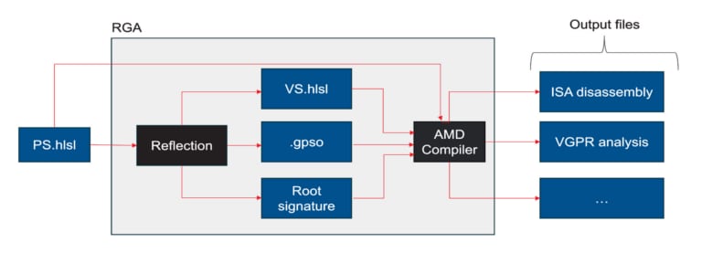
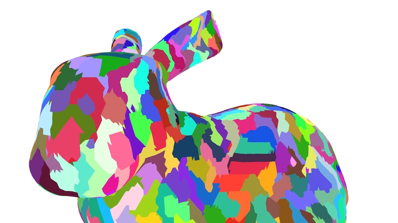
In this blog-post we demonstrate per-primitive attributes and how they can be used to simplify font-rendering. Per-primitive attributes were introduced with mesh shaders. With the font-rendering technique that we use here, we get infinite level-of-detail with just one draw call per string, but only with mesh shaders. We found this to be a nice, easy enough, practical, and useful example to explore new features coming with mesh shaders.
|
Zoom |
Debug View |
|---|---|
|
|
|


Introduction
Font rendering is probably one of the most widespread computer graphics problems. In fact, you are reading a blog post right now, that you would not be able to read if there was no font-rendering. Due to its omnipresence, we take font-rendering for granted, but rarely acknowledge its challenges or even appreciate its algorithms.
A font consists of glyphs. A glyph is a graphical representation of a character, such as a letter, a digit, a symbol, etc. Font rendering is the process of drawing a string of glyphs onto a raster display.
In this blog post, we show how mesh shaders can be used for Loop’s and Blinn’s 2005 SIGGRAPH paper “Resolution independent curve rendering using programmable graphics hardware”.
Their original vertex shader pipeline implementation, however, suffers from three drawbacks:
-
Vertex duplication of shared control points of curved glyphs. This results in undesired redundancy.
-
The method requires three different primitive types, which necessitates up to three draw calls per glyph.
-
Rendering a string involves exhaustive API overhead, since we have to issue up to three draw-calls per character. This causes inefficiencies particularly for those glyphs that contain only a few triangles.
As an improvement, we make the following contributions:
-
To remove vertex duplication, we suggest to use barycentric coordinates provided by the rasterization stage. This is, however, not a feature that comes with mesh shaders. In fact, it has been around for a while, but it makes our mesh shader implementation simpler.
-
We avoid superfluous draw-calls by per-primitive attributes introduced by mesh shaders. Effectively, a glyph can be represented using a single vertex- and index-buffer plus a novel per-primitive-attribute buffer. With this additional per-primitive-attribute buffer, a single dispatch suffices to render a glyph.
-
With our mesh shader implementation, all we need to do is upload the string that you wish to render to a GPU buffer. Then a single mesh shader-dispatch renders an entire string.
The method we propose here also works for vector-art. A comparative case study on performance and performance optimizations are, however, beyond the scope of this blog-post. This post should primarily focus on per-primitive attributes, a feature that comes with mesh shaders, demonstrate it on a practical example, and maybe give you some inspiration.
Glyph representation
We obtain our fonts from the true-type font format (TTF). There, glyphs consist of two types of curves: linear curves, which are in fact line segments, and quadratic curves. We use linear curves for straight edges, found in letters like “L”, quadratic curves model round shapes found in characters such as the period/point/full-stop symbol “.”, and mixtures of linear and quadratic curves are present in letters such as in the letter “S”. In the figures, we highlight line segments using violet strokes, and quadratic curves using orange strokes. End-points of the segments are marked with black dots.
|
Lines |
Curves |
Lines & Curves |
|---|---|---|
|
|
|
|


Multiple curves are organized to form a closed continuous spline, i.e., an ordered sequence of curves. Adjacent curves meet in a single common point. That is why the spline is called continuous. Additionally, the first and the last curve need to be adjacent, too. Then, the spline forms a loop. That is why we call the spline closed. The glyphs, “L”, “.”, and “S” above are examples where a glyph consists of only one single closed continuous spline.
A glyph may consist of multiple splines, such as a semi-colon “;” which consists of two splines. Splines can even be nested to form characters like a “O”:
|
Two Separate Splines |
Two Nested Splines |
|---|---|
|
|
|


To determine whether a point needs filling, we shoot a ray from that point into an arbitrary direction. If that ray hits the splines an even number of times, then we are outside the filled part.
Font rendering according to Loop and Blinn
TTF represents linear and quadratic curve segments with Bézier curves: For linear curve segments, the formula is:
\vec{f}(t) = (1-t)\cdot\vec{a} + t\cdot\vec{b},\quad t\in\left[0\dots 1\right]
and for quadratic Bézier curves segments
\vec{f}(t) = (1-t)^2\cdot\vec{a} + 2(1-t) t \cdot \vec{c}+t^2\cdot\vec{b},\quad t\in\left[0\dots 1\right],
where \vec{a}, \vec{c}, and \vec{b} are control points. The non-alphabetic order is not a typo: It is made such that in both cases \vec{a} and \vec{b} are the end-points of the curve segment.
Loop and Blinn render both types of curves, but quadratic curves are more interesting. Consider the right-parenthesis glyph “)”:

It consists of four quadratic segments with control points \left(\vec{a}_0,\vec{c}_0,\vec{b}_0\right), \left(\vec{a}_1,\vec{c}_1,\vec{b}_1\right), \left(\vec{a}_3,\vec{c}_3,\vec{b}_3\right), and \left(\vec{a}_4,\vec{c}_4,\vec{b}_4\right). It also has two linear segments: \left(\vec{a}_2,\vec{b}_2\right) and \left(\vec{a}_5,\vec{b}_5\right).
To get an “edgy” approximation of the glyph, we compute a triangulation of the point set \left\lbrace\vec{a}_i, \vec{b}_i, \vec{c}_i\right\rbrace under the following constraints:
-
Keep edge \left(\vec{a}_i, \vec{b}_i\right) in case the quadratic curve is a convex outline or the curve is linear;
-
Keep edges \left(\vec{a}_i, \vec{c}_i\right), \left(\vec{c}_i, \vec{b}_i\right) in case the quadratic curve is a concave outline.
In our parenthesis example \left(\vec{a}_0,\vec{c}_0,\vec{b}_0\right), \left(\vec{a}_1,\vec{c}_1,\vec{b}_1\right) are convex and \left(\vec{a}_3,\vec{c}_3,\vec{b}_3\right), \left(\vec{a}_4,\vec{c}_4,\vec{b}_4\right) are concave. An example triangulation is shown here:
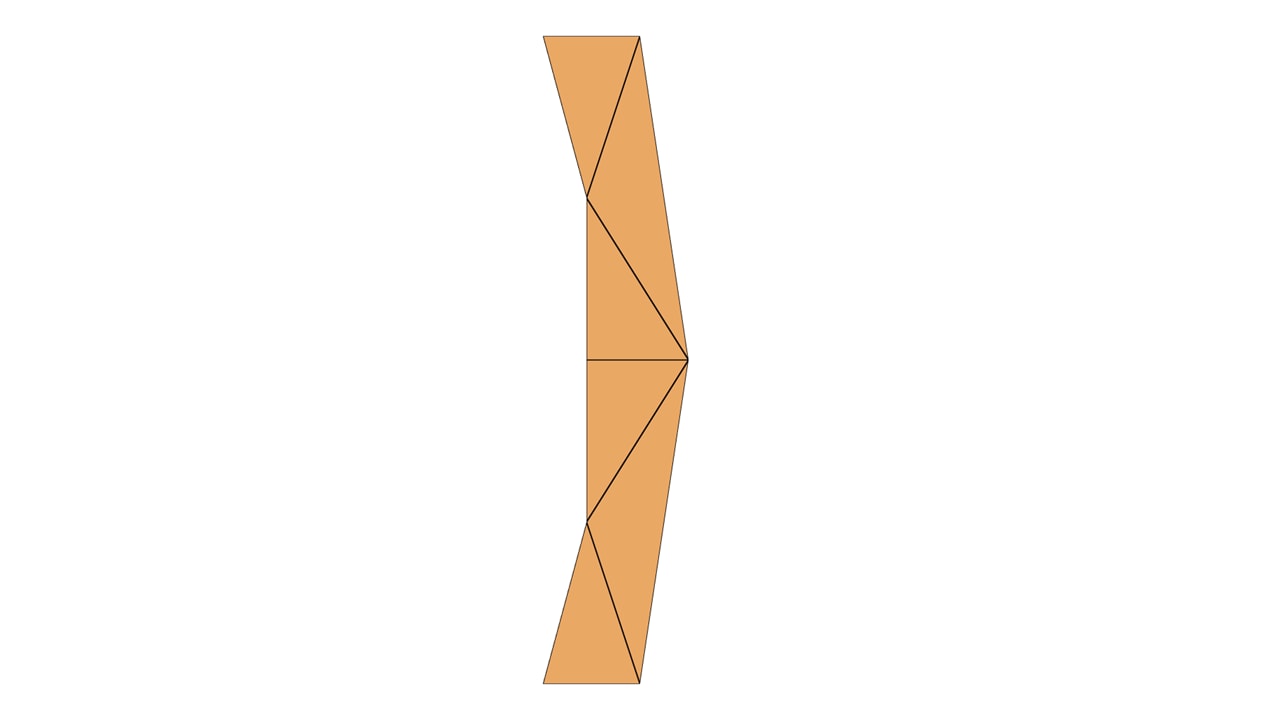
We call the triangles of the “edgy approximation” solid triangles. However, the glyph still looks edgy. To get a smooth silhouette, we need to add the quadratic Bézier curves shown in blue for convex and red for concave, below.

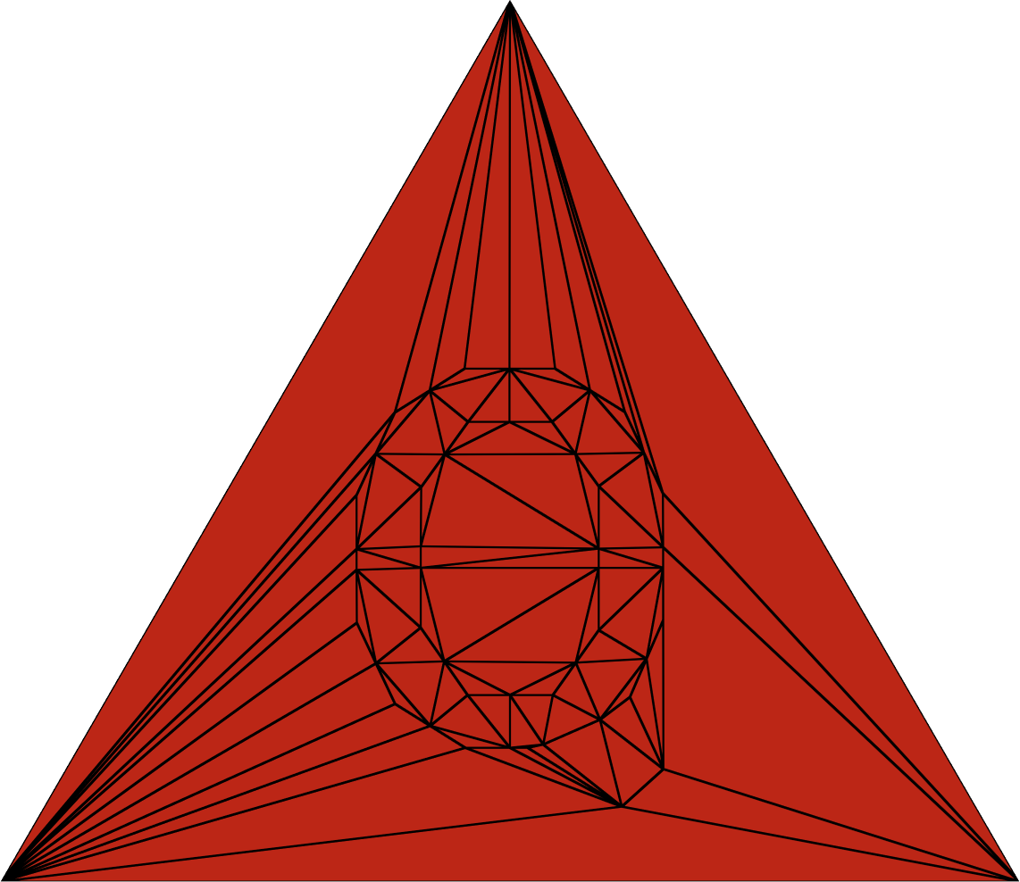
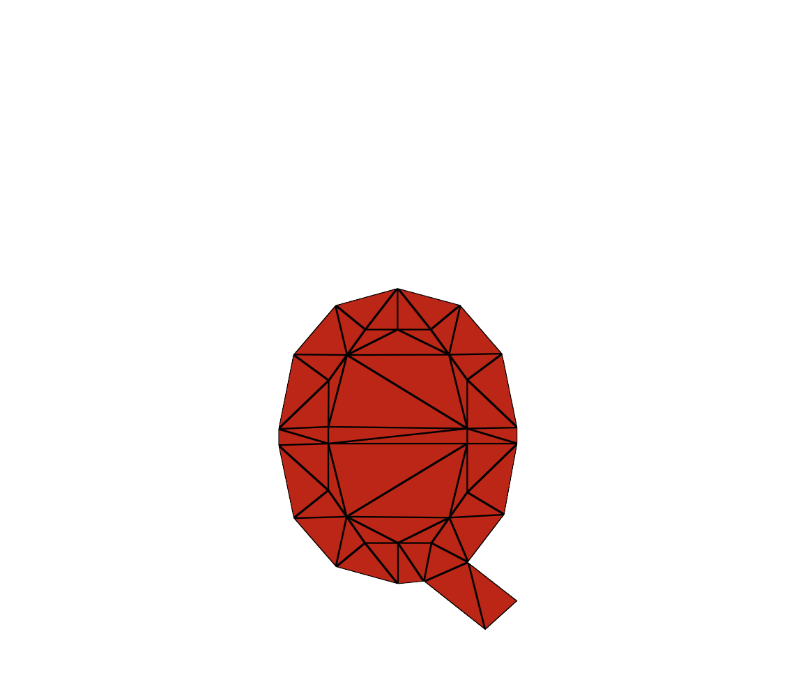
Before we go into the details of how to render the Bézier curves, let’s quickly outline how to find the solid triangles first. There, we use one of the many open-source packages that produce what is called a Constrained Delaunay Triangulation. They typically do standard convex Delaunay triangulations (left), can remove outside triangles (middle), and even detect holes (right). We use the latter one for fonts:
|
With outer triangles |
Without outer triangles, but with filled holes |
With outer triangles and holes removed |
|---|---|---|
|
|
|
|

We can render the result as a regular triangle mesh with an index- and vertex buffer using the traditional vertex shader pipeline.
Now, we have the solid triangles covered. Next, we have, however, to deal with the triangles that form the quadratic Bézier curves (i.e., the blue and the red triangles from before).
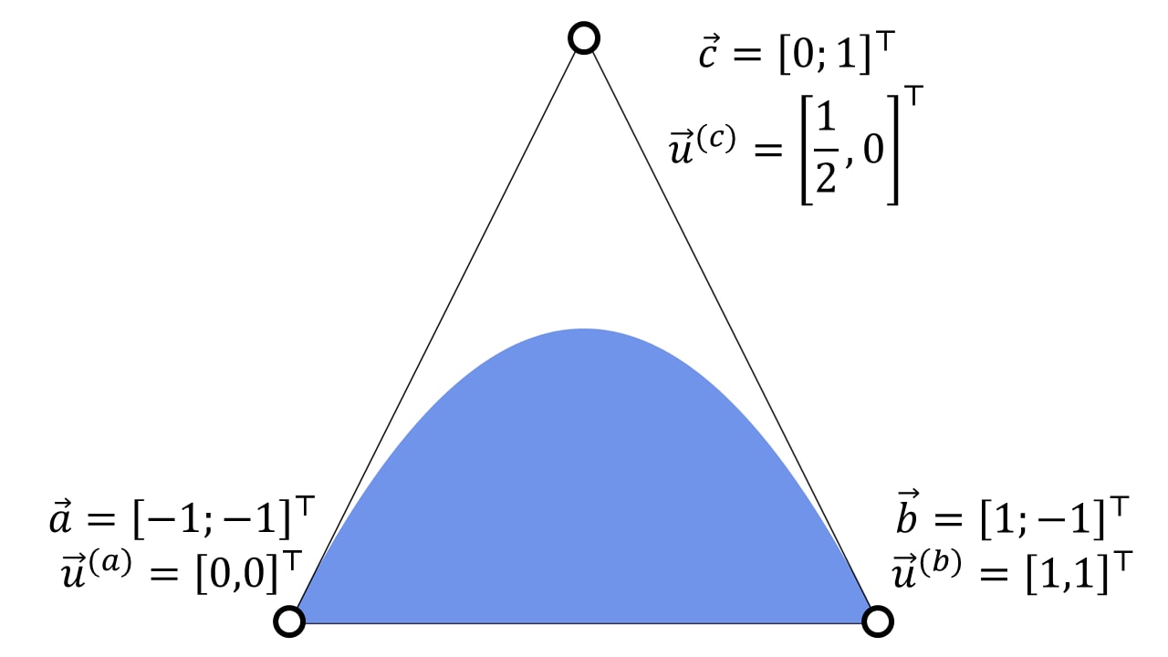
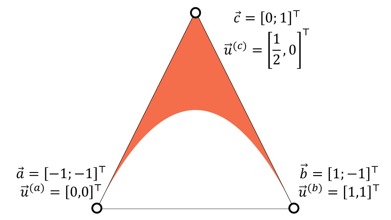
To render a quadratic Bézier curve, Loop and Blinn suggest to render a triangle as follows:
-
Each vertex encodes
-
a vertex position: control points \vec{a}, \vec{c}, \vec{b} of the quadratic Bézier curve and
-
a 2D coordinate \vec{u}: 2D canonical quadratic Bézier curve \vec{u}^{(a)}=\left[0;0\right]^\top, \vec{u}^{(c)}=\left[\frac{1}{2};0\right]^\top, and \vec{u}^{(b)}=\left[1;1\right]^\top, and
-
-
depending on whether we want convex or concave curves, the pixel shader discards pixels for which the interpolated \vec{u}=[u,v]^\top’s is either
-
u^2-v > 0 or
-
u^2-v < 0, respectively.
This renders quadratic Bézier curves by discarding pixels on one side of Bézier curve within the triangle. The resulting filled areas form a convex or concave region:
|
Convex |
Concave |
|---|---|
|
|
|
Here is why this works: looking at the coordinates of the canonical quadratic Bézier curve, we get
\begin{bmatrix}u\\v\end{bmatrix} = \begin{bmatrix}0\\0\end{bmatrix}(1-t^2)+ 2(1-t)t\begin{bmatrix}\frac{1}{2}\\0\end{bmatrix}+ t^2\begin{bmatrix}1\\1\end{bmatrix}= \begin{bmatrix}t\\t^2\end{bmatrix},
This directly gives a condition if a point is on that curve u^2-v = 0. We discard pixels that pass the < and > comparisons against 0 for concave and convex fills, respectively.
Loop’s and Blinn’s observation is that the rasterization stage interpolates \left[u;v\right]^\top. This carries out an affine transformation from the positions of the quadratic Bézier curve with the control points \vec{a}, \vec{c}, and \vec{b} in to the coordinate space of canonical Bézier curve with the control points \left[0;0\right]^\top, \left[\frac{1}{2};0\right]^\top, and \left[1;1\right]^\top. Since Bézier curves are invariant under affine transformations, the simple predicate works for all \vec{a}’s, \vec{c}’s, and \vec{b}’s.
To render a glyph, Loop and Blinn distinguish between three triangle types:
-
Solid triangles,
-
triangles with convex curves, and
-
triangles with concave curves.
Therefore, we create three index buffers in a pre-process. For our example of a “)” we would get:
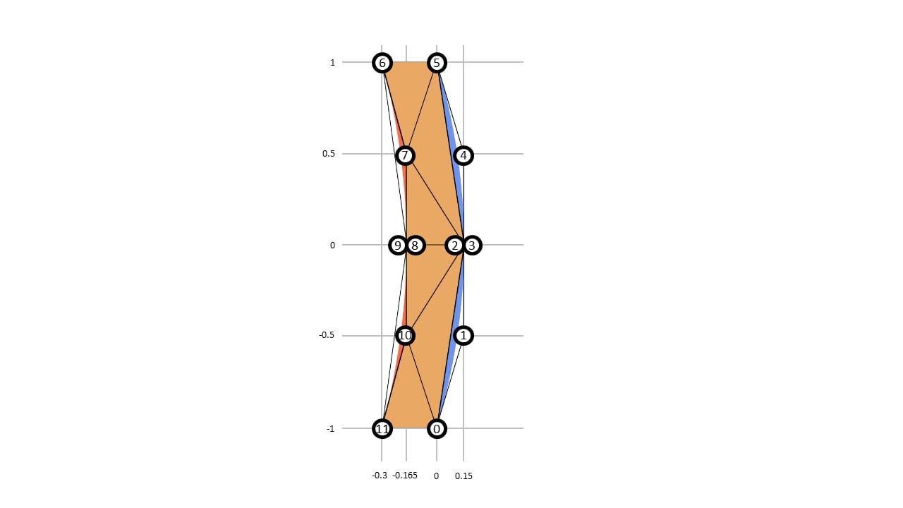
Vertex Buffer:
|
Index |
0 |
1 |
2 |
3 |
4 |
5 |
6 |
7 |
8 |
9 |
10 |
11 |
|---|---|---|---|---|---|---|---|---|---|---|---|---|
|
x |
+0.000 |
+0.150 |
+0.150 |
+0.150 |
+0.150 |
+1.000 |
-0.300 |
-0.165 |
-0.165 |
-0.165 |
-0.165 |
-0.300 |
|
y |
-1.000 |
-0.500 |
+0.000 |
+0.000 |
+0.500 |
+1.000 |
+1.000 |
+0.500 |
+0.000 |
+0.000 |
-0.500 |
-1.000 |
|
u |
+0.000 |
+0.500 |
+1.000 |
+0.000 |
+0.500 |
+1.000 |
+0.000 |
+0.500 |
+1.000 |
+0.000 |
+0.500 |
+1.000 |
|
v |
+0.000 |
+0.000 |
+1.000 |
+0.000 |
+0.000 |
+1.000 |
+0.000 |
+0.000 |
+1.000 |
+0.000 |
+0.000 |
+1.000 |
Index Buffer for Solid Triangles
|
Index |
0 |
1 |
2 |
3 |
4 |
5 |
|---|---|---|---|---|---|---|
|
i0 |
11 |
10 |
2 |
8 |
7 |
7 |
|
i1 |
0 |
0 |
8 |
2 |
2 |
5 |
|
i2 |
10 |
2 |
10 |
7 |
5 |
6 |
Index Buffer for Triangles with Convex Curves:
|
Index |
0 |
1 |
|---|---|---|
|
i0 |
0 |
3 |
|
i1 |
1 |
4 |
|
i2 |
2 |
5 |
Index Buffer for Triangles with Concave Curves:
|
Index |
0 |
1 |
|---|---|---|
|
i0 |
6 |
9 |
|
i1 |
7 |
10 |
|
i2 |
8 |
11 |
Note that, while the vertices with, e.g., index 2 and 3 share the same position, they do have different canonical coordinates. The same holds for vertex indices 8 and 9.
For conventional vertex-pipeline rendering, the reasonable thing to do is to issue three draw calls, one for each index buffer. However, three draw calls create more API overhead than a single draw call. Therefore, we will now show how to simplify glyph rendering to a single draw call with per-primitive attributes.
Removing vertex duplication
Neighboring triangles of the same curve type might share a common point, i.e., \vec{a}_{i}=\vec{b}_{i+1} . However, the underlying \left[u;v\right]^\top coordinates required for the canonical quadratic Bézier curve are \left[1;1\right]^\top at \vec{b}_{i} and \left[0;0\right]^\top at \vec{a}_{i+1} . This makes vertex re-use impossible. One way of circumventing vertex-duplication is to exploit symmetry properties of Bézier curves, but the problem of unwanted vertex duplication cannot be solved entirely. Another disadvantage of carrying the canonical Bézier curve along is to store an extra vertex attribute.
As a solution, we propose not to store the control points of the canonical quadratic Bézier curve, thus the values for \left[u;v\right]^\top, at all. Instead, we compute the interpolated \left[u;v\right]^\top in the pixel shader from barycentric coordinates:
Copied!
float2 computeUV(const float3 bary)
{
    // The three control points a, c, b of the canonical Bézier curve:
    float2 a = float2(0.0f, 0.0f);
    float2 c = float2(0.5f, 0.0f);
    float2 b = float2(1.0f, 1.0f);
    // Explicitly carry out the interpolation using barycentrics.
    return bary.x * a + bary.y * c + bary.z * b;
}
We can obtain the barycentric coordinates from SV_BARYCENTRICS semantic in the input structure of the pixel shader
Copied!
struct PixelIn
{
    float4 position : SV_POSITION;
    float3 bary     : SV_BARYCENTRICS;
}
Therefore, we only need the positions of the quadratic Bézier curves in a vertex buffer. We can even share the vertices with solid triangles. This removes the need for two per-vertex attributes and solves vertex duplication: 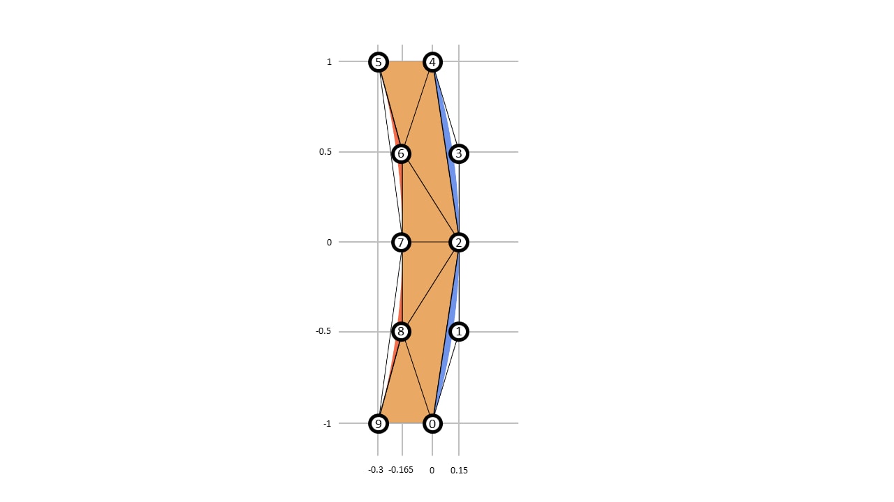
There, the vertex buffer has less attributes and less vertices:
|
Index |
0 |
1 |
2 |
3 |
4 |
5 |
6 |
7 |
8 |
9 |
|---|---|---|---|---|---|---|---|---|---|---|
|
x |
+0.000 |
+0.150 |
+0.150 |
+0.150 |
+1.000 |
-0.300 |
-0.165 |
-0.165 |
-0.165 |
-0.300 |
|
y |
-1.000 |
-0.500 |
+0.000 |
+0.500 |
+1.000 |
+1.000 |
+0.500 |
+0.000 |
-0.500 |
-1.000 |
But we are still stuck with three index buffers, i.e., one index buffer for solid triangles
|
Index |
0 |
1 |
2 |
3 |
4 |
5 |
|---|---|---|---|---|---|---|
|
i0 |
9 |
8 |
2 |
7 |
6 |
6 |
|
i1 |
0 |
0 |
8 |
2 |
2 |
4 |
|
i2 |
8 |
2 |
7 |
6 |
4 |
5 |
one index buffer for convex triangles,
|
Index |
0 |
1 |
|---|---|---|
|
i0 |
0 |
2 |
|
i1 |
1 |
3 |
|
i2 |
2 |
4 |
and one index buffer for concave triangles:
|
Index |
0 |
1 |
|---|---|---|
|
i0 |
5 |
7 |
|
i1 |
6 |
8 |
|
i2 |
7 |
9 |
Therefore, we still need three draw calls. What we actually want is an attribute per-primitive where we encode the triangle type and hand that over to the raster stage. However, this is not supported by the traditional vertex shader pipeline and this is where the modern mesh shader pipeline comes into play.
Per-primitive attributes to avoid superfluous draw-calls
Since mesh shaders do not rely on a fixed input format consisting of a vertex- and index-buffer, we are free to read any data we want from GPU memory. All we have to do is hand triangles over to the raster stage. So, for our little bracket example, we create a buffer for the vertex positions and an index buffer that assembles all the triangles together. But now, we add a third buffer, which we call the primitive attribute buffer. That stores whether the triangle has a convex curve, a concave curve or a solid triangle:
|
Index |
0 |
1 |
2 |
3 |
4 |
5 |
6 |
7 |
8 |
9 |
|---|---|---|---|---|---|---|---|---|---|---|
|
i0 |
9 |
8 |
2 |
7 |
6 |
6 |
0 |
2 |
5 |
7 |
|
i1 |
0 |
0 |
8 |
2 |
2 |
4 |
1 |
3 |
6 |
8 |
|
i2 |
8 |
2 |
7 |
6 |
4 |
5 |
2 |
4 |
7 |
9 |
|
Primitive Attribute Buffer |
Solid |
Solid |
Solid |
Solid |
Solid |
Solid |
Convex |
Convex |
Concave |
Concave |
For explanatory purposes, we simply define the geometry directly in the HLSL code:
Copied!
static const float2 pos[] =
{
    { +0.000, -1.00 }, // 0
    { +0.150, -0.50 }, // 1
    { +0.150, +0.00 }, // 2
    { +0.150, +0.50 }, // 3
    { +0.000, +1.00 }, // 4
    { -0.300, +1.00 }, // 5
    { -0.165, +0.50 }, // 6
    { -0.165, +0.00 }, // 7
    { -0.165, -0.50 }, // 8
    { -0.300, -1.00 }, // 9
};

static const uint3 tri[] =
{
    // Filled Triangles
    { 4, 5, 6 }, // 0
    { 4, 6, 2 }, // 1
    { 6, 7, 2 }, // 2
    { 7, 8, 2 }, // 3
    { 2, 8, 0 }, // 4
    { 9, 0, 8 }, // 5
    // Convex curve triangles
    { 0, 1, 2 }, // 6
    { 2, 3, 4 }, // 7
    // Concave curve triangles
    { 5, 6, 7 }, // 8
    { 7, 8, 9 }, // 9
};

static const uint SOLID = 0;
static const uint CONVEX = 1;
static const uint CONCAVE = 2;

static uint primAttr[] =
{
    SOLID,   // 0
    SOLID,   // 1
    SOLID,   // 2
    SOLID,   // 3
    SOLID,   // 4
    SOLID,   // 5
    CONVEX,  // 6
    CONVEX,  // 7
    CONCAVE, // 8
    CONCAVE, // 9
};
So, we let our mesh shader output a maximum of 128 triangles (out indices uint3 outputTriangles[128]) and 64 vertices (out vertices VertOut outputVertices[64]). Additionally to that, we have to emit 128 attributes per mesh shader workgroup (out primitives PrimOut outputPrimAttr[128]). We tweaked the parameters here to best fit our test font, which never requires more than 128 triangles or 64 vertices per glyph. We could batch glyphs together to increase the vertex and triangle count, but this is, however, an optimization that we defer to future work. This results in the following input signature of our mesh shader:
Copied!
[NumThreads(128, 1, 1)]
[OutputTopology("triangle")]
void MSMain(
    uint tid : SV_GroupThreadID,                // thread id within the thread group
    out indices uint3 outputTriangles[128],
    out vertices VertOut outputVertices[64],
    out primitives PrimOut outputPrimAttr[128] // NEW when using primitive attributes!
    )
Each element of outputTriangles is a uint3, i.e., three integers pointing to a per-mesh shader thread group. Each output vertex in outputVertices is a struct holding the position:
Copied!
struct VertOut
{
    float4 position     : SV_POSITION;
};
Now, this is where things get interesting. We have a struct for the primitives we emit outputPrimAttr:
Copied!
struct PrimOut
{
    uint triangleType   : BLENDINDICES0;
};
Next, we set the number of output primitives and vertices:
Copied!
const uint nVerts = sizeof(pos) / sizeof(float2);
const uint nPrims = sizeof(tri) / sizeof(uint3);
SetMeshOutputCounts(nVerts, nPrims);
output the vertices
Copied!
if (tid < nVerts)
{
    outputVertices[tid].position = float4(pos[tid].xy, 0.0f, 1.0f);
}
Finally, we write primitives, including the new and fancy per-primitive attributes:
Copied!
if (tid < nPrims)
{
    outputTriangles[tid]             = tri[tid];       // regular mesh shader code to output triangles
    outputPrimAttr[tid].triangleType = primAttr[tid];  // NEW when using primitive attributes!
}
The pixel shader then consumes the attributes as follows:
Copied!
struct PixelIn
{
    float4 position   : SV_POSITION;
    float3 bary       : SV_BARYCENTRICS;
    uint triangleType : BLENDINDICES0;
};
Note that the mesh shader outputs the per-vertex attributes position and the per-primitive attribute triangleType into two distinct structs. The pixel shader, however, consumes them in a single struct. The connection between mesh shader-output-structs and pixel-shader-input-struct is made over the semantics BLENDINDICES0 and SV_POSITION.
Based on the per-primitive attribute, we can now decide whether the fragment, that the pixel shader processes, originated from a convex curve, a concave curve, or a solid triangle, and discard the fragments, accordingly.
Copied!
float4 PSMain(PixelIn p) : SV_TARGET
{
    const uint t    = p.triangleType;      // the per-primitive attribute. It is constant for all fragments!
    const float2 uv = computeUV(p.bary);   // map back to the canonic Bézier curve
    const float y   = uv.x * uv.x - uv.y;  // evaluate the canonic Bézier curve.

    // for triangle containing convex and concave curve, decide whether we are inside or outside of Bézier curve.
    if (((t == CONVEX) && (y > 0.0f)) || ((t == CONCAVE) && (y < 0.0f)))
    {
      discard;
    }
    // In case of a solid triangle or a non-discarded fragment of a left- or right-triangle.
    return float4(1, 0, 0, 1);
}
You find the entire shading code in the appendix.
A single mesh shader dispatch to render an entire string
We now sketch out a how a simple font rendering system could work. In a pre-process, we compute and upload the information for each glyph, as well as structures to quickly access them in a mesh shader. Then during run-time, we upload a string and render it using mesh shaders.
Pre-process
For each ASCII character, we create a glyph mesh, which we call a glyphlet. We put the geometry information of all glyphlets in a large GPU vertex-, index-, and per-primitive-buffer.
To obtain the geometry information of each glyphlet during rendering, we need to be able to index into these buffers correctly. Therefore, we store a GlyphletInfo for each glyph
Copied!
struct GlyphletInfo {
    unsigned int vertexBaseIndex;   // Index to the first vertex in the large vertex buffer.
    unsigned int triangleBaseIndex; // Index to the first triangle in the index-buffer and
                                    // per-primitive attribute buffer.
    unsigned int vertexCount;       // Number of vertices for that glyph.
    unsigned int primitiveCount;    // Number of primitives for that glyph.
};
and keep a GPU-array that contains a GlyphletInfo for each character. We can directly use the ASCII code of the character to index into the array.
In the HLSL code, we use StructuredBuffers to access the arrays
Copied!
// Large vertex buffer containing the vertex positions of all glyphlets.
StructuredBuffer<float2> vertexBuffer         : register(t0);
// Large index buffer containing the index buffer of all glyphlets.
StructuredBuffer<uint3> indexBuffer           : register(t1);
// Large index buffer containing the per-primitive information for all glyphlets.
StructuredBuffer<uint> perPrimitiveBuffer     : register(t2);

// Buffer to find starting position of for each glyphlet in the vertexBuffer,
// indexBuffer, and per-primitive buffer.
StructuredBuffer<GlyphletInfo> glyphletBuffer : register(t3);
Run-time
To render a string at run-time, we copy all its characters and store their positions to an array:
Copied!
/// This is CPU Code
struct CharacterRenderInfo {
    float2 pos;         // position of the char.
    uint   character;   // which char (8 bits would be enough, but D3D12 wants 32 Bit at least)
};
std::vector<CharacterRenderInfo> textToRender;
Every time the string changes, we copy textToRender to a GPU-buffer.
Copied!
// Buffer that needs to be rendered
StructuredBuffer<CharacterRenderInfo> textToRender : register(t4);
Then, we dispatch as many thread-groups, as we have characters in the string. Each thread-group renders one glyph: We use the group-thread id SV_GroupID to find the character in the GPU copy of textToRender:
Copied!
[NumThreads(128, 1, 1)]
[OutputTopology("triangle")]
void MSMain(
    uint gtid : SV_GroupThreadID,
    uint gid : SV_GroupID,
    out indices uint3 outputTriangles[128],
    out vertices VertOutput outputVertices[128],
    out primitives PrimOutput outputPrimAttr[128])
{

    const uint glyphIndex = textToRender[gid].character;
With the character, we can index into array with GlyphletInfos.
Copied!
const GlyphletInfo glyphletInfo = glyphletBuffer[glyphIndex];
and tell the raster stage how many primitives and vertices we wish to output:
Copied!
SetMeshOutputCounts(glyphletInfo.vertexCount, glyphletInfo.primitiveCount);
What’s left is to copy the glyphlet to the mesh shader output buffers:
Copied!
    if (gtid < glyphletInfo.primitiveCount)
    {
        outputTriangles[gtid]             = indexBuffer[glyphletInfo.triangleBaseIndex + gtid];
        outputPrimAttr[gtid].triangleType = perPrimitiveBuffer[glyphletInfo.triangleBaseIndex + gtid];
    }
    if (gtid < glyphletInfo.vertexCount)
    {
        float2 position               = vertexBuffer[glyphletInfo.vertexBaseIndex + gtid] + text[gid].pos.xy;
        outputVertices[gtid].position = mul(DynamicConst.transformationMatrix, float4(position, 0.0f, 1.0f));
    }
}
This allows for resolution independent rendering of strings in real-time:
It even works with multi-sampled anti-aliasing (MSAA): simply turn on MSAA and activate sample shading. This can be done by adding the sample keyword right before float3 bary:
Copied!
struct PixelIn
{
    float4 position          : SV_POSITION;
    // Add sample & enable MSAA for Anti-aliasing
    sample float3 bary       : SV_BARYCENTRICS;
    uint triangleType        : BLENDINDICES0;
};
Results, discussion, conclusion, and future work
We test our system on an AMD Radeon™ RX 7600 card. It works nice and fast, but we have not yet carried out a comparative study on performance.
We showed that mesh shaders can improve the GPU implementation of Loop’s and Blinn’s font-rendering algorithm. Our mesh shader implementation improves over a traditional vertex-shader-pipeline-based implementation in terms of memory-space requirements, usability, and simplicity.
Note that, our mesh shader implementation does not require geometry as primary input. In contrast, it reads a string and creates the mesh of that string from glyphlets, i.e., small index-, vertex-, and per-primitive-buffers. Hence, the geometry of the string is directly created on-chip right in the middle of the graphics pipeline.
Please be aware, that this is no way a fully fleshed out / exhaustive glyph renderer. There are way more edge -cases, pitfalls, and performance considerations than we could fit into a single blog-post.
Appendix: HLSL code
Copied!
static const uint SOLID = 0;
static const uint CONVEX = 1;
static const uint CONCAVE = 2;

static const float2 pos[] =
{
    { +0.000, -1.00 }, // 0
    { +0.150, -0.50 }, // 1
    { +0.150, +0.00 }, // 2
    { +0.150, +0.50 }, // 3
    { +0.000, +1.00 }, // 4
    { -0.300, +1.00 }, // 5
    { -0.165, +0.50 }, // 6
    { -0.165, +0.00 }, // 7
    { -0.165, -0.50 }, // 8
    { -0.300, -1.00 }, // 9

};

static const uint3 tri[] =
{
    // CONVEX curve triangles
    { 0, 1, 2 }, // 0
    { 2, 3, 4 }, // 1
    // CONCAVE curve triangles
    { 5, 6, 7 }, // 2
    { 7, 8, 9 }, // 3
    // Filled Triangles
    { 4, 5, 6 }, // 4
    { 4, 6, 2 }, // 5
    { 6, 7, 2 }, // 6
    { 7, 8, 2 }, // 7
    { 2, 8, 0 }, // 8
    { 9, 0, 8 }, // 9
};


static uint primAttr[] =
{
    CONVEX,  //0
    CONVEX,  // 1
    CONCAVE, // 2
    CONCAVE, // 3
    SOLID,   // 4
    SOLID,   // 5
    SOLID,   // 6
    SOLID,   // 7
    SOLID,   // 8
    SOLID,   // 9
};

struct VertOut
{
    float4 position     : SV_POSITION;
};

struct PrimOut
{
    uint triangleType   : BLENDINDICES0;
};

struct PixelIn
{
    float4 position    : SV_POSITION;
    sample float3 bary : SV_BARYCENTRICS;
    uint triangleType  : BLENDINDICES0;
};

[NumThreads(128, 1, 1)]
[OutputTopology("triangle")]
void MSMain(
    uint tid : SV_GroupThreadID,
    out indices uint3 outputTriangles[128],
    out vertices VertOut outputVertices[64],
    out primitives PrimOut outputPrimAttr[128])
{
    const uint nVerts = sizeof(pos) / sizeof(float2);
    const uint nPrims = sizeof(tri) / sizeof(uint3);

    SetMeshOutputCounts(nVerts, nPrims);

    if (tid < nPrims)
    {
        outputTriangles[tid] = tri[tid];
        outputPrimAttr[tid].triangleType = primAttr[tid];
    }
    if (tid < nVerts)
    {
        outputVertices[tid].position = float4(0.9 * pos[tid].xy, 0.0f, 1.0f);
    }
}

float2 computeUV(const float3 bary)
{
    const float u = bary.x * 0 + bary.y * 0.5f + bary.z * 1;
    const float v = bary.x * 0 + bary.y * 0.0f + bary.z * 1;
    return float2(u, v);
}

float computeQuadraticBezierFunction(const float2 uv)
{
    return uv.x * uv.x - uv.y;
}

float4 PSMain(PixelIn p) : SV_TARGET
{
    const uint   t  = p.triangleType;
    const float2 uv = computeUV(p.bary);
    const float  y  = computeQuadraticBezierFunction(uv);

    if (((t == CONVEX) && (y > 0.0f)) || ((t == CONCAVE) && (y < 0.0f)))
    {
        discard;
    }

    return float3(1, 0, 0, 1);
}
Disclaimers
Links to third-party sites are provided for convenience and unless explicitly stated, AMD is not responsible for the contents of such linked sites, and no endorsement is implied. GD-98