AMD FidelityFX™ Variable Shading
AMD FidelityFX Variable Shading drives Variable Rate Shading into your game.
Following our introductory blog post in which we explored mesh shaders and the Next Generation Geometry pipeline, we will cover some best practices for writing mesh- and amplification shaders. In the second part of this post, we will also look at how the AMD Radeon™ Developer tools can be used to profile and optimize mesh shaders.
The best practices below should be seen as guidelines for using the mesh shading pipeline in a optimal way. Depending on your application and requirements, some of the recommendations may not fully apply. We will provide our guidelines with the reasons for choosing them, so you can decide whether this reasoning also applies to your applications, and thus form an informed decision.
In this first section, we’ll discuss some considerations for choosing the parameters for meshlet generation. A meshlet consist of vertices and triangles. Typically, meshlet builders receive upper limits for both values, and , as an argument.
Different graphics APIs and vendors limit the maximum output amount of both values individually to different values between 256 and 1024 per thread group.
In the case of Direct3D12, both the number of vertices and primitives per meshlet are limited to 256.
As a rule of thumb, the ratio between the values for a 2-manifold-ish meshlet is .
This gives an idea about what value of the two will be the limiting factor for the size of the majority of meshlets:
The vertex transformation usually is the main compute workload of a mesh shader. Therefore, to allow for a higher compute utilization inside each thread group, it makes sense to set such that it is a multiple of the thread group size and so it is not the limiting factor.
Given that mesh shader indices can only reference vertices inside the same meshlet, vertices along the edge of the meshlet have to be duplicated and also processed more than once.
Thus, meshlet generation can be seen similar to vertex cache optimization, with the main difference being that vertex duplication for meshlets is directly determined upfront by the meshlet generator and not by the graphics card hardware, thereby giving developers full control over how vertices are processed.
The meshlet builder will try to find coherent sets of triangles within limits and and use similar criteria as for vertex cache reuse optimization:
Each included vertex should be used by as many included triangles as possible.
In general, the bigger a meshlet, the better the ratio between the border edge length and the total meshlet area becomes.
Thus, we suggest to generate meshlets of size and , as this strikes a good balance between overall performance and vertex duplication.
The and configuration recommended by Christoph Kubisch1 yields similar performance at the expense of duplicating more vertices.
Revisiting the Stanford Bunny mesh from the first blog post with its almost 35 thousand vertices and almost 70 thousand triangles, we can see how statically partitioning the mesh into meshlets can yield lower vertex duplication rates than a vertex cache optimized mesh. In addition, these lower vertex reuse rates are vendor and hardware generation independent.
| Mesh | Optimized Mesh | Meshlets2 | |
|---|---|---|---|
| Transformed Vertices | 143.9k | 48.9k | 43.2k |
| Duplication Factor | 4.13 | 1.40 | 1.24 |
| Visualization: Different colors represent different primitive subgroups or meshlets. | 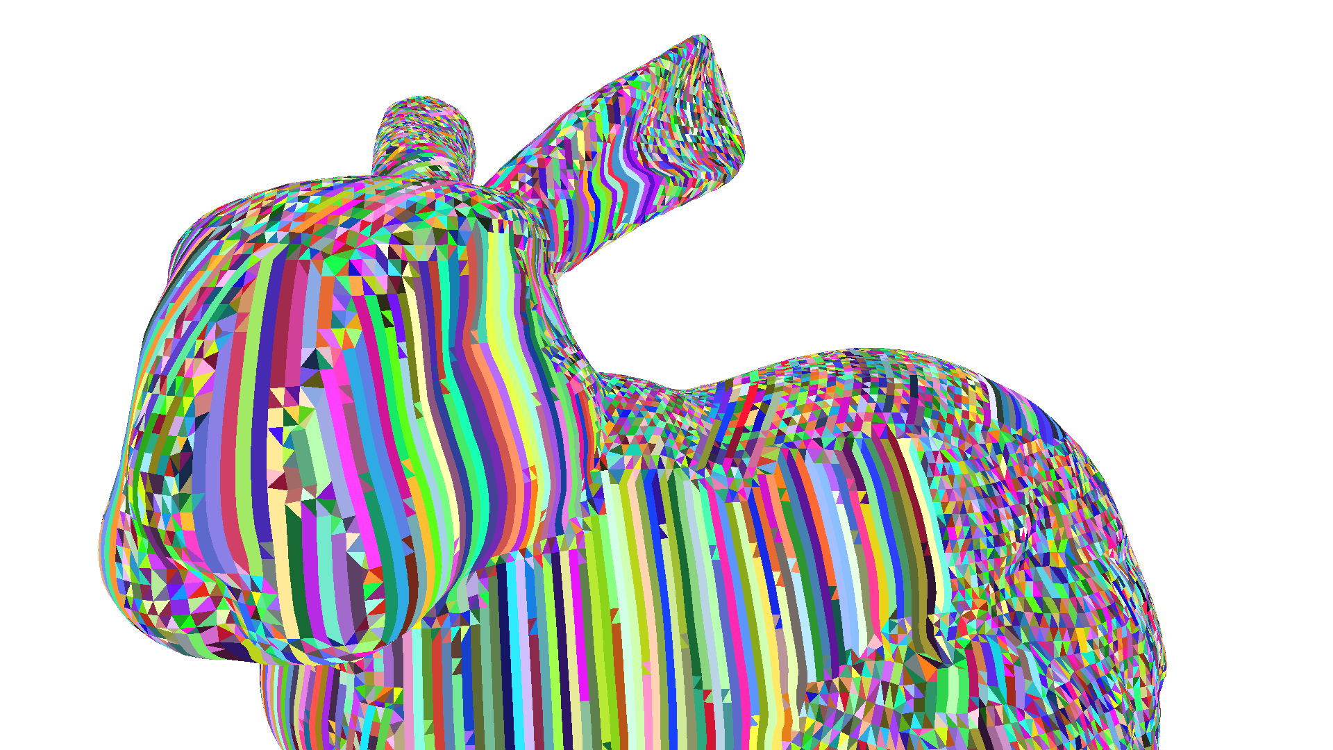 | 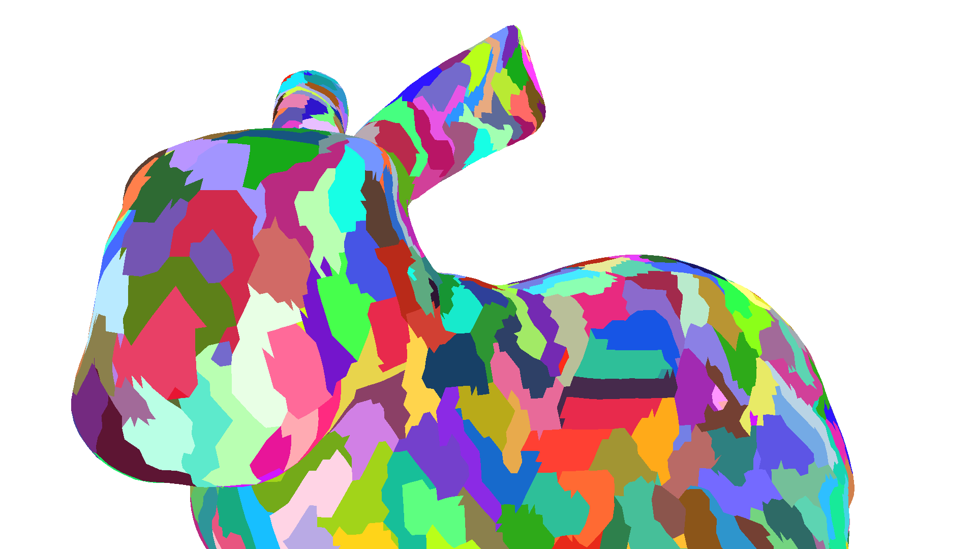 |  |
In addition, some meshlet generators also consider other criteria for meshlet generation, such as the size of the culling bounding volume(s) or vertex and topology compressibility. Both will be explained in the a future post.
After establishing some guidelines for generating meshlets, we will now focus on some best practices for processing said meshlets in a mesh shader.
As discussed before, vertex transformation is likely to be the main compute workload of the mesh shader and therefore we recommend setting the thread groups size to match the maximum number of vertices in a meshlet. In case, that is not possible, try to at least divide the maximum number of vertices in a meshlet evenly across the threads. In the case of Direct3D12, the thread group size is limited to 128 threads, thus matching our recommended meshlet size of . In order to utilize the GPU’s parallel architecture, we recommend setting the thread group size to 128, thereby enabling a 1:1 mapping of threads and vertices. In case of a lower vertex limit, e.g., , we recommend only adjusting the thread group size if is below 128, as - in most cases - having a dedicated thread for exporting extra primitives is faster. Our experiments show that if mesh shader occupancy is heavily limited by pixel shader or other dispatches running in parallel, reducing thread group size to e.g., 64 can yield small performance uplifts.
The output of a mesh shader is defined as arrays in the function signature of the mesh shader.
void MeshShader(..., out vertices VertexAttribute verts[128], out indices uint3 triangles[256])The size of these arrays represents - from the perspective of the GPU - the worst case for vertex and primitive output. Thus, the geometry engine uses these limits to reserve output space in the shader export before launching a mesh shader thread group.
Therefore, these limits should be set as low as possible, i.e., in the case of pre-computed meshlet to and .
The vertices and indices arrays shown above are shared across the thread group and any thread can write to any element of the array.
The mesh shader has to transfer the data written to these array to the shader export for the primitive assembler to assemble and rasterize the triangles.
On RDNA™ graphics cards, the exp instruction is used to export a single primitive or vertex to the shader export.
The order of primitives and vertices in the shader export is defined by the order of threads in the thread group, i.e., the -th thread in the thread group will write to the -th vertex or primitive in the shader export.
For vertices this means that the -th thread has to export the -th vertex, otherwise triangles would be assembled incorrectly. For primitive connectivity information, the Microsoft DirectX® 12 Mesh Shader specification imposes the following constraints on the rasterization order:
Triangles generated by any individual mesh shader thread group are always retired by the rasterizer in the order that thread group specified it’s primitive outputs.
Thus, the -th thread also must export the -th primitive in order to adhere to this constraint.
If the -th thread did not produce the -th vertex or primitive, i.e., another thread has written to verts[i] or triangles[i], vertex and/or primitive information must be exchanged between thread via the group shared memory.
This increases latency and resource requirements of the mesh shader.
If mesh shader writes verts[i] and triangles[i] from the -th thread, then these values can be directly exported to the shader export without being passed through group shared memory.
As the maximum thread group size is limited to 128 in Direct3D12, but the maximum number of vertices and primitives can be up to 256, threads have to write multiple vertices or primitives in some cases.
On graphics cards with the RDNA™ 2 architecture, threads are limited to a single vertex and primitive export. Thus the thread group is extended with additional, hidden threads to export the remaining vertices and primitives.
Data is exchanged with these thread via group shared memory.
Graphics cards with the RDNA™ 3 architecture can specify a wave-wide offset to the exp instruction and are thus able to export the -th and -th vertex or primitive from the -th thread. The offset in this case is usually 128.
In summary, we recommend writing the -th vertex and -th primitive from -th thread in the thread group.
If vertex or primitive count exceeds the thread group size, e.g., in the above recommended and configuration, we recommend to write vertices and primitives with a thread-group-sided stride, e.g., the -th thread writes triangles[i] and triangles[i + 128].
The code below shows an example mesh shader exporting up to 128 vertices and up to 256 primitives.
[numthreads(128, 1, 1)][outputtopology("triangle")]void MeshShader(in uint groupId : SV_GroupID,                in uint threadId : SV_GroupThreadID,                out vertices VertexAttribute verts[128],                out indices uint3 triangles[256],                out primitives PrimitiveAttribute prims[256]){    Meshlet meshlet = meshlets[groupId];
    SetMeshOutputCounts(meshlet.vertexCount, meshlet.primitiveCount);
    for (uint i = 0; i < 2; ++i) {        const uint primitiveId = threadId + i * 128;
        if (primitiveId < meshlet.primitiveCount) {            triangles[primitiveId] = LoadPrimitive(meshlet, primitiveId);            prims[primitiveId] = LoadPrimitiveAttributes(meshlet, primitiveId);        }    }
if (threadId < meshlet.vertexCount) { verts[threadId] = LoadVertex(meshlet, threadId); }}As discussed above, the geometry engine has to reserve output space in the shader export before launching a mesh shader thread group. Space in the shader export is finite and can thus limit the overall mesh shader occupancy to a GPU-wide maximum number of mesh shader thread groups. Shader export memory size is designed such that regular mesh shaders can reach the rasterizer triangle throughput. For simple mesh shaders, this means that a occupancy of ~25% can be enough to reach the triangle throughput limit.
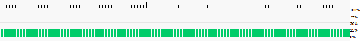
More complex mesh shaders may see slightly higher occupancy, but also tend to be limited by available memory in the shader export. Thus, we recommend to only perform required computations in the mesh shader and pre-process any other data beforehand, e.g., vertex reuse information for primitives.
The compute-like programming model of mesh shaders also enables the use of group shared memory for communication between threads or waves. However, as group shared memory is limited and allocating larger amounts decrease overall (mesh-) shader occupancy, we recommend to not use group shared memory to temporarily store all vertices or primitives of a mesh shader thread group.
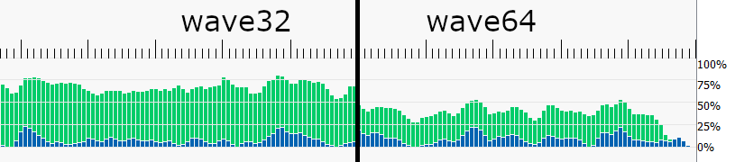
Mesh Shaders are typically compiled in wave64 mode, i.e., 64 threads per wave, which means only two waves are needed for a thread group size of 128 threads.
Using certain instructions, e.g. WavePrefixSum, may cause the shader to be compiled in wave32 mode, thus requiring twice as many waves to execute the same thread group.
This also causes mesh shader occupancy to appear higher without running more thread groups in parallel.
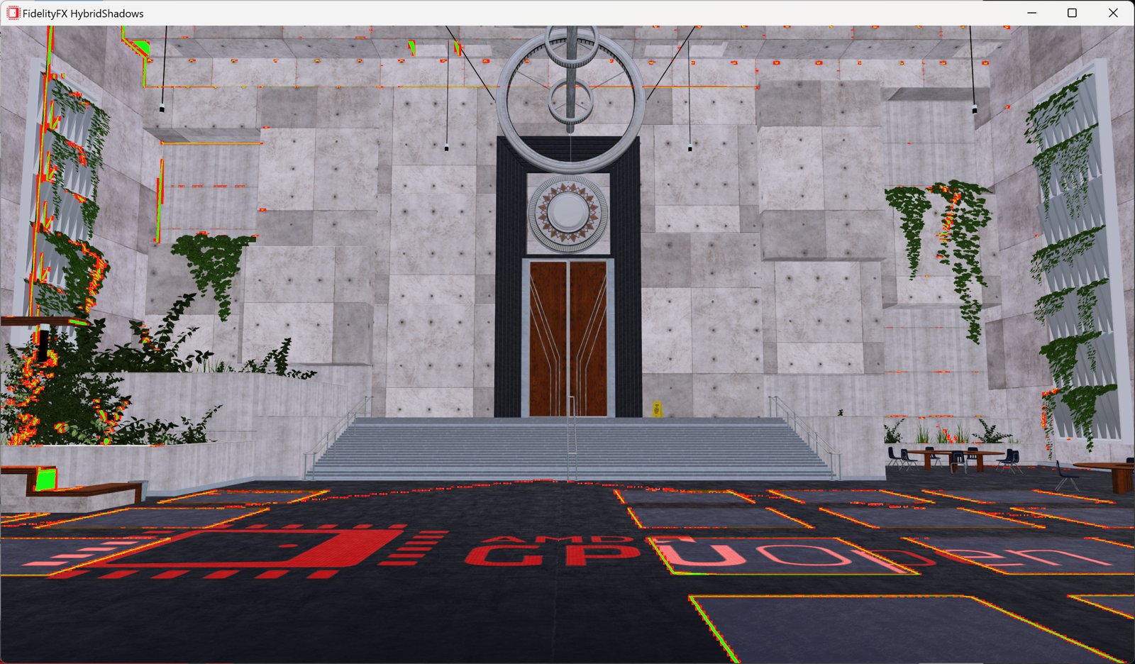
Occupancy of mesh shaders can also be temporarily limited by pixel shader thread groups if, for example, one or more meshlets cover enough screen area to fill the GPU with pixel shader operations.
Pixel shaders are in this case prioritized over mesh shaders to relieve output pressure from the rasterizer.
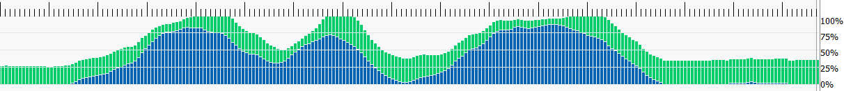 Mesh Shader occupancy (green) is limited by pixel shader workload (blue).
In addition to the per-vertex attribute data, mesh shaders can also specify per-primitive attributes. In the pixel shader, these attributes can be read like any other per-vertex attribute, with the main difference being that these attributes are not interpolated across the primitive.
struct PrimitiveAttribute {    float4 primitiveColor : COLOR0;}
[numthreads(128, 1, 1)][outputtopology("triangle")]void MeshShader(...                out primitives PrimitiveAttribute prims[256]){    prims[primitiveId] = LoadPrimitiveAttributes(meshlet, primitiveId);}
Passing certain attributes as primitive attributes can reduce vertex duplication and/or help reduce memory traffic by reducing the overall size of the attribute memory written by the mesh shader. Some examples include flat-shading, whereby the normal attribute is specified per-primitive, rather than per-vertex or texture mapping systems like Ptex, which specify different texture coordinates for each primitive. Writing these attributes as primitive attributes allows the pixel shader to still read the correct attribute values without duplicating the vertex.
SV_CullPrimitive if you need to cull some triangles between other, visible triangles.
The primitive assembler can load multiple triangles for assembly and discard any culled primitives with minimal overhead.
These culled primitives will however still count towards the total primitive count of the mesh shader.SetMeshOutputCounts early on in the mesh shader.
This call will reserve output memory for storing vertex and primitive attributes (other than the vertex position).
Requesting memory early helps hiding the latency required for memory allocation in the geometry engine.Amplification shaders, as the name implies, can be used to amplify the workload of a mesh shader draw call directly on the GPU. This system does, however, come with some caveats and some performance considerations need to be kept in mind.
As described in the first blog post, mesh shaders have a compute-like programming model, but still need to be launched through the geometry engine in order to reserve output space for indices and vertex positions in the shader export.
In addition to this requirement, we also want the amplified work to be executed across the entire GPU, thereby making use of the massive parallelism available on modern GPUs.
To enable a load-balanced launch of mesh shaders through the geometry engine, the DispatchMesh intrinsic calls are communicated back to the command processor and processed in much the same way as DispatchMesh commands from the CPU.
To comply with the specified rasterization order, the command processor has to adhere to a strict order for processing these commands.
Commands need to be executed in the same order as the amplification shader thread groups were launched.
This whole process comes at the expense of added latency to the rendering process. To recover this latency, a high enough amplification rate, i.e., the average number of mesh shader thread groups launched by a single amplification shader thread group is needed.
In scenarios in which the amplification shader performs per-meshlet culling operations, i.e., checking per-element visibility of a pre-determined set of meshlets, we recommend to process at least 32 or 64 elements, e.g., meshlets, per amplification shader thread group.
By choosing the amplification shader thread group size accordingly, culling can be implemented using the WavePrefixCountBits and WaveActiveCountBits wave intrinsics on RDNA™ graphics cards.
bool visible = false;const int meshletId = threadId;if (meshletId < meshletCount){    visible = IsMeshletVisible(Meshlets[meshletId]);}
if (visible){    const uint idx = WavePrefixCountBits(visible);    payload.meshletIds[idx] = meshletId;}
const uint meshletCount = WaveActiveCountBits(visible);DispatchMesh(meshletCount, 1, 1, payload);
Increasing the number of elements processed by a single amplification shader thread group reduces the number of commands sent back to the command processor and thereby reduces latency.
For other applications, such as dynamic level-of-detail selection or geometry amplification (e.g., subdivision surfaces), a similar principle applies. A single amplification shader thread group should typically launch at least 32 mesh shader thread groups to optimally hide the added latency.
An amplification shader thread group can further output a payload of up to 16k bytes. All mesh shader thread groups launched by that amplification shader thread group have access this 16k payload. This payload needs to be stored in memory in order for the mesh shaders to read it and thus needs to be written to memory by the amplification shader. Larger payloads can thus be quite costly in terms of memory usage and memory read/write operations. We recommend to keep the amplification shader payload size to a minimum and only transfer data that cannot be directly loaded, computed, or inferred by the mesh shader.
A typical amplification shader payload contains an array of parameters, with each element being processed by one or more of the subsequently launched mesh shader thread groups. If each element of the payload is only written by one thread, the compiler can optimize writes to the payload and directly write the element to memory.
In this last section, we will show how mesh shaders can be profiled and optimized using the Radeon™ Developer Tool Suite, in particular the Radeon™ GPU Profiler (RGP).
With version 1.15, the Radeon™ GPU Profiler added support for mesh shader events.
DispatchMesh commands are now shown in the event timing view and are also shown under most expensive events.
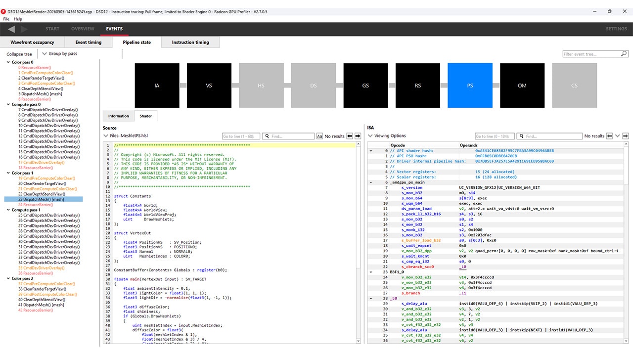
In the wavefront occupancy timeline, mesh shaders are shown as geometry shaders (GS) along with cache counters and the event below.
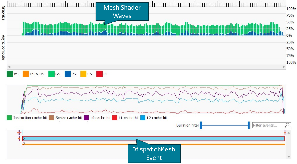
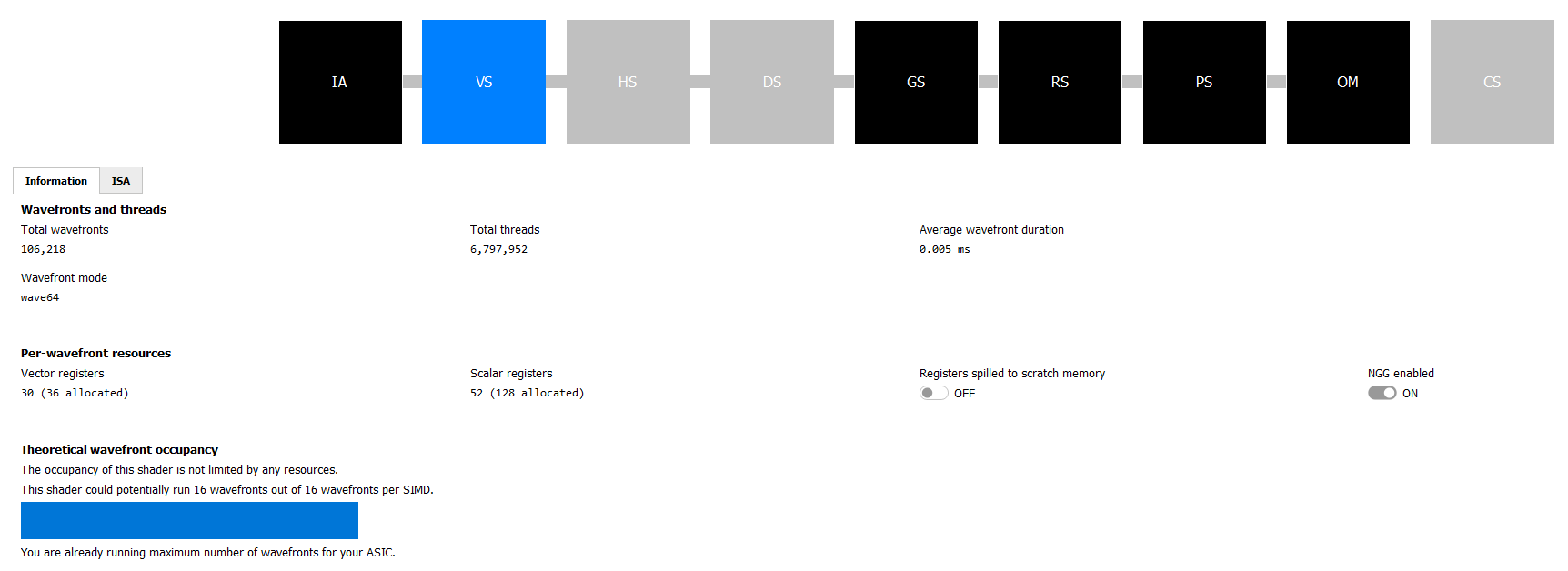
Below, the mesh shader pipeline state can be seen in the VS and GS shader stages.
Here you can see the total number of wavefronts and threads launched for the DispatchMesh command as well as the wavefront mode.
As described in the mesh shader occupancy optimizations in the previous section, this can have a significant impact on the displayed wave occupancy without changing the number of concurrent mesh shader thread groups.
If instruction tracing was enabled while capturing the trace and a sufficient number of mesh shader waves were launched, the mesh shader instruction timing can be seen under the VS or GS pipeline stages.
Most notably, the instruction timing also includes export instructions which are used to send primitive or vertex information to the shader export.
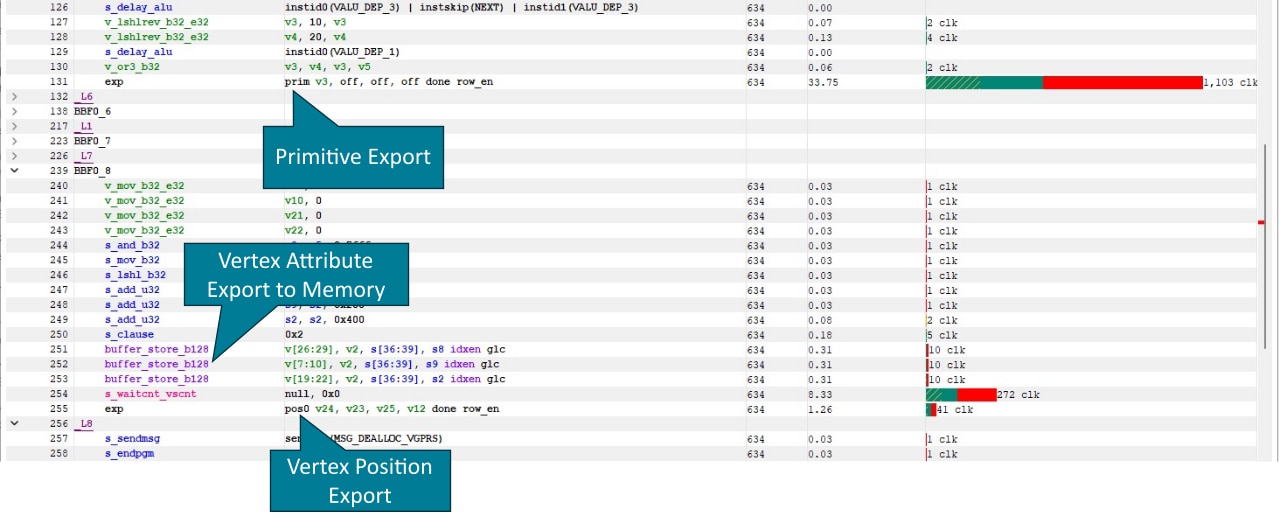
exp prim stores primitive connectivity for a single primitive and exp pos0 a single vertex position.
On RDNA™ 3 graphics cards, vertex attributes, such as normal or texture coordinates are stored in memory.
On RDNA™ 2 graphics cards, the vertex attributes are written using exp param{n} instructions.
High export instruction latency, particularly on the first exp instruction can be seen as an indicator that the mesh shader is limited by rasterizer throughput.
Export is only possible after the shader has send a MSG_GS_ALLOC_REQ message, which sends the vertex and primitive count of the mesh shader thread group as specified by SetMeshOutputCounts.

Calling SetMeshOutputCounts early on in the mesh shader helps hiding the latency of sending this command.
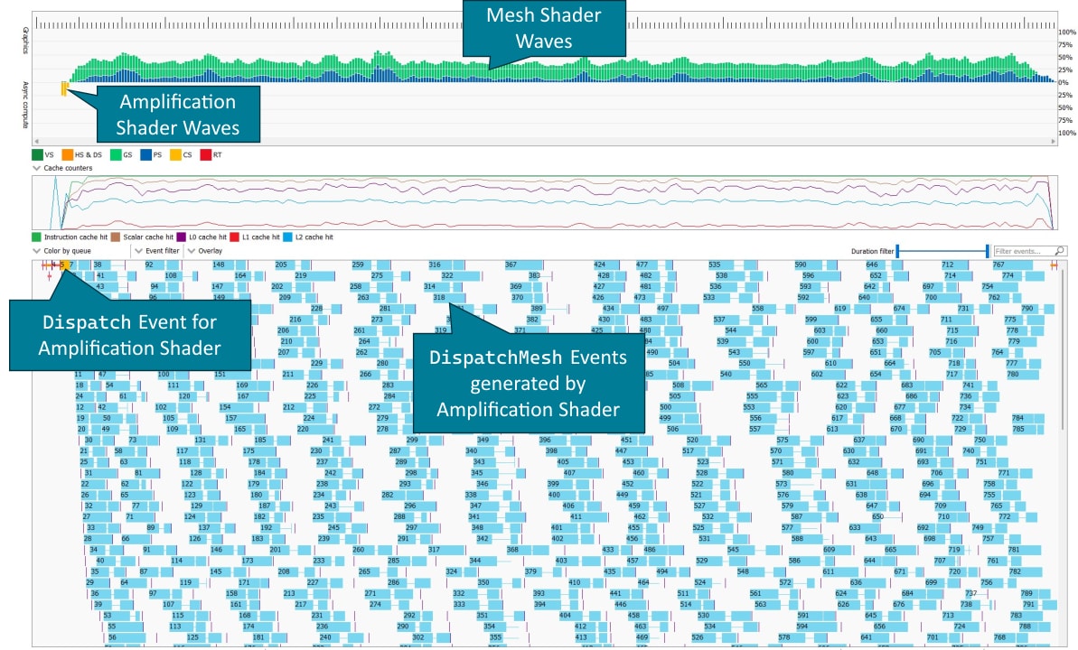
Amplification shaders are executed as compute shaders on the async compute queue and thus are shown as such in RGP. Mesh shader dispatches issued by the amplification shader are shown as individual events. As these events often only consist of a hand full of thread groups, instruction timings for mesh shaders may not be available or are slightly inaccurate due to the small number of samples.
The number of mesh shader thread groups in each mesh shader dispatches issued by the amplification shader is reflected in the total number of PrimS wavefronts. This information can be found in the details pane, when in Wavefront occupancy view or the in the VS/GS pipeline state.
| Details Pane | Pipeline State |
|---|---|
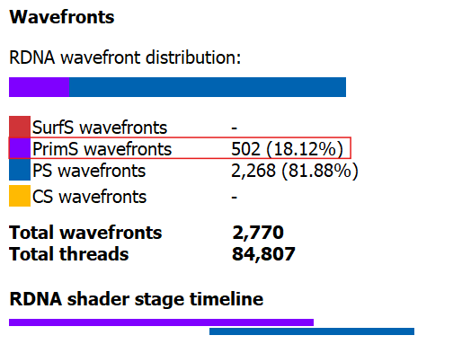 | 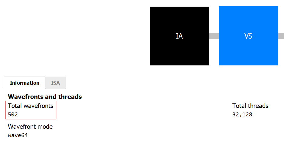 |
Amplification shaders send dispatch commands and payloads back to the command processor via a memory ring buffer.
To ensure the rasterization order specified for amplification shaders, the entries in this ring buffer are assigned to amplification shader thread groups in the order that the thread groups are launched.
If a dispatch contains more amplification shader thread groups than entries in the ring buffer, the command processor issues secondary amplification shader dispatches for the remaining thread groups once entries in the ring buffer become available.
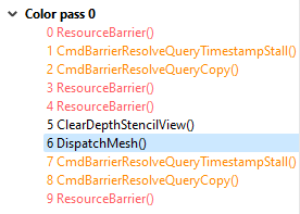
These secondary dispatches are shown in RGP as Dispatch(0, 0, 0) events.
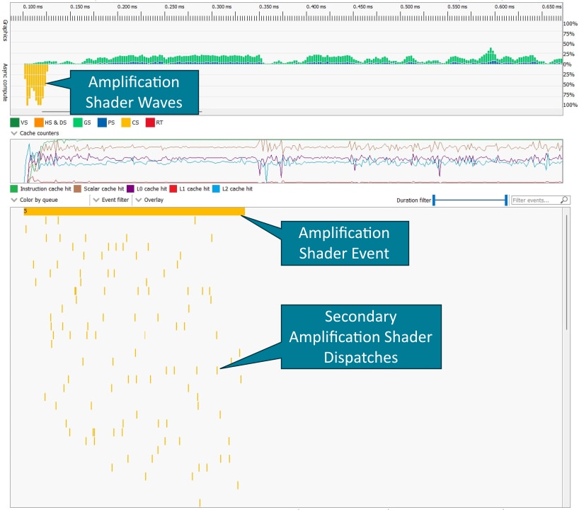
The initial amplification shader dispatch (event 5) spans the entire duration of all amplification shader dispatches.
The command processor has to process entries in the ring buffer in sequential order.
If multiple amplification shader thread group in a row do not launch any mesh shader thread groups, the graphics card can run out of mesh shader work, which can be seen in the gaps between mesh shader events below.
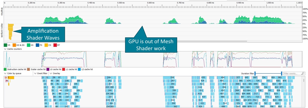
In such scenarios, we recommend to increase the number of meshlets processed by a single amplification shader thread group.
In this blog post, we described best practices for amplification and mesh shader development as well as how to profile them.
For mesh-shaders, we gave guidance on the meshlet’s vertex and triangle count, the thread group size of a mesh-shader, and how to best hand vertices and primitives to the rasterizer.
Further, we showed what is computationally feasible for mesh shaders and concluded with additional optimization guidelines.
For amplification shaders, we provided recommendations on the thread group size and how to efficiently pass data to mesh-shaders launched by amplification shaders.
Finally, we demonstrated how amplification and mesh shaders can be profiled with our Radeon™ GPU Profiler.
Links to third-party sites are provided for convenience and unless explicitly stated, AMD is not responsible for the contents of such linked sites, and no endorsement is implied. GD-98
Microsoft is a registered trademark of Microsoft Corporation in the US and/or other countries. Other product names used in this publication are for identification purposes only and may be trademarks of their respective owners.
DirectX is a registered trademark of Microsoft Corporation in the US and/or other countries.
Using meshlet generator provided as part of zeux’ meshoptimizer. ↩