AMD FidelityFX™ Variable Shading
AMD FidelityFX Variable Shading drives Variable Rate Shading into your game.
On this page
We continue our mesh shader use-case studies by taking a look at meshlet compression.
In detail, we want to show how to diminish the memory footprint of meshlet geometry, thus both the index buffer and the vertex attributes. Decompression then happens on the fly on every frame in the mesh shader.
This project dates back to 2010, the time Quirin, one of this post’s authors, decompressed generalized triangle strips (GTS) in parallel on the GPU for his PhD thesis (see also a paper and a talk on that matter). The algorithm shares similarities with Epic Games’ GTS decompression introduced with Nanite in 2021. In 2010, however, compute shaders, as we know them today, did not exist, yet. Compute pipelines were separate APIs and thus a switch between graphics and compute was very expensive and slowed the overall rendering-time.
The introduction of mesh shaders allowed for a tighter integration of graphics and compute. Therefore, Quirin and some of his students at Coburg University of Applied Sciences started working on various projects in the context of mesh-shader decompression in 2020. One project really took on speed, when the people from AMD in Munich were joining and also sparked the creation of this mesh shader blog post series. In our latest paper, Towards Practical Meshlet Compression, we show how combining these compression technique with mesh shaders can both increase render performance and decrease memory consumption. In this blog post, we would like to take a deeper dive into some of the more technical aspects of said paper, which is available here.

Meshes created with scanning techniques such as photogrammetry become more and more common in real-time applications. To cope with the large amounts of geometry data, Unreal Engine introduced Nanite. Nanite demonstrates that today it is feasible to stream in massive amounts of geometry, even to an extent where triangles are smaller than a pixel. To handle such amounts of data, one key element of Nanite is geometry compression. While typically decompression algorithms run in a linear manner, to run well on a graphics card, decompression has to be parallelized. At the time of us writing this post, the developers of Nanite aren’t satisfied with the GPU decompression performance, so they only run it once after streaming from the CPU, instead of performing it every frame as originally intended see Nanite presentation from 2021.
Next, we will show a closely related method to Nanite’s encoding, optimized to be used directly in a mesh shader. Subsequently, we will discuss amplification shader based meshlet culling, as it also fits the topic of rendering predefined geometry.
In real-time graphics, a mesh usually consists of triangles. Each triangle consists of three indices to vertex attributes. An index buffer
V=[V0,V1,V2,V3,V4,V5,V6,V7,V8…]represents the connectivity of a triangle mesh. Commonly, a GPU interprets V as a triangle list, where triples of indices in V form the triangles:
(V0,V1,V2),(V3,V4,V5),(V6,V7,V8)…Or here in a concrete example:
However, with three indices per triangle, their storage requirement is relatively high.
A less memory intense way to interpret V are triangle strips, where a triangle reuses an edge of the preceding triangle:
(V0,V1,V2),(V4,V5,V6),(V3,V2,V1),(V7,V6,V5),(V2,V3,V4),(V6,V7,V8),(V5,V4,V3),…Note that we inverted the vertex order in every second triangle to keep the winding order intact. Now, each triangle in the strip requires only one new index, except for the first one. Thus, using strips results in a 3:1 compression ratio.
Triangle strips describe a path over the triangles of a mesh. The previous example was of an alternating triangle strip, where the strip alternates between reusing the right and the left edge of the previous triangle. As this is not very flexible, we can introduce another bit flag per triangle that encodes which edge is reused, which we call the L/R flag. This is called a generalized triangle strip or GTS and is what we use for our meshlets. Our previous example encoded as a GTS could look like this:
Note that we also ordered the vertices of the meshlet, so that they appear in incrementing order in the strip. As this way, the first indices (0,1,2) are mandatory, we don’t need to store them.
To entirely represent a mesh, or in our case a meshlet, multiple strips are typically required. To describe multiple strips as a single one, we need a way to encode a strip restart. This can either be done by adding another restart bit per triangle, or by intentionally adding degenerate triangles to the strip.
A degenerate triangle has two or more identical vertex indices, thus its area is zero. As they will not change the result of the rendered image, the rasterizer of a GPU can just ignore them. For example, the index buffer for an alternating strip
[V0,V1,V2,V3,V3,V4,V4,V5,V6]with the duplicated vertices V3,V4 produces four degenerate triangles:
(V0,V1,V2),(V3,V4,V4),(V3,V2,V1),(V5,V4,V4),(V2,V3,V3),(V4,V5,V6).(V4,V3,V3),As you can see, we successfully ended a strip on a triangle (V3,V2,V1) and started a new one with triangle (V4,V5,V6). Using degenerate triangles instead of bit flags comes with the benefit that no additional logic is required in the decompression stage. The rasterizer will just ignore all degenerate triangles.
When encoding a meshlet in a GTS, the number of triangles grows when requiring a restart. Thus, in very rare cases, the number of triangles can exceed the 256 limit. In such a case, we choose to split the meshlet in two.
Finding good strips through a meshlet that only require a low number of restarts is a non-trivial problem. For a good tradeoff between run-time performance and quality, we recommend to use the enhanced tunneling algorithm. In our paper “Towards Practical Meshlet Decompression”, we describe an optimal algorithm, but that takes some time to compute.
As established in the previous section, a L/R flag per triangle marks which edge of the previous triangle is reused. As all triangles are decompressed in parallel, a thread cannot access the decompressed previous triangle. Instead, each individual thread must find the correct indices from earlier in the strip. See the next figure for reference: the longer the strip spins around vertex in a fan-like manner, the further back the required index lies.
To find out how far exactly we have to go back in the strip, we count (starting with 1) how many steps we have to go back in the L/R bit mask until a change of flag occurs. In our example, triangle 7 requires the index of triangle 4, which is 0. To do this search in linear time, we can use the bit operation firstbithigh (or firstbitlow) in hlsl or findMSB (or findLSB) in glsl. Note that the bit mask has to be shifted and inverted accordingly.
This can be implemented in hlsl like the following:
uint LoadTriangleFanOffset(in int triangleIndex, in bool triangleFlag){    uint lastFlags;    int fanOffset = 1;    do    {        // Load last 32 L/R-flags        lastFlags = LoadLast32TriangleFlags(triangleIndex);        // Flip L/R-flags, such that        //  0 = same L/R flag        //  1 = different L/R flags, i.e. end of triangle fan        lastFlags = triangleFlag ? ~lastFlags : lastFlags;        // 31 - firstbithigh counts leading 0 bits, i.e. length of triangle fan        fanOffset += 31 - firstbithigh(lastFlags);        // Move to next 32 L/R flags        triangleIndex -= 32;    }    // Continue util    // - lastFlags contains different L/R flag (end of triangle fan)    // - start of triangle strip was reached (triangleIndex < 0)    while ((lastFlags == 0) && (triangleIndex >= 0));
    return fanOffset;}
We have to use a loop here, because a fan-like configuration could be longer than 32 triangles. In most cases, this loop will only run once. In the worst case, the whole strip is actually a fan, so the loop will run 256/32=8 times (256, because it is the maximum amount of triangles a mesh shader can output and 32, because we store one bit per triangle in a 32-bit dword). Inside the loop, we load the L/R bits in a way that the most significant bit is the flag of the current triangle, the second most significant bit is the form the previous triangle, and so on:
// 256/32 = 8 dwords for flags and 256 / 4 = 64 dwords for 8 bit indicesgroupshared uint IndexBufferCache[8 + 64];
uint LoadLast32TriangleFlags(in int triangleIndex){    // Index of DWORD which contains L/R flag for triangleIndex    int dwordIndex = triangleIndex / 32;    // Bit index of L/R flag in DWORD    int bitIndex   = triangleIndex % 32;
    // Shift triangle L/R flags such that lastFlags only contains flag prior to triangleIndex    uint lastFlags = IndexBufferCache[dwordIndex] << (31 - bitIndex);
    if (dwordIndex != 0 && bitIndex != 31)    {        // Fill remaining bits with previous L/R flag DWORD        lastFlags |= IndexBufferCache[dwordIndex - 1] >> (bitIndex + 1);    }
    return lastFlags;}
As you can see here, we do something we recommended in the previous posts of this series: make use of the group shared memory. In detail, instead of every thread having its own copy of the whole compressed strip, or loading that data from global memory multiple times, we load the data once and cache it in group shared memory. This improves run-time performance.
Finally, the whole triangle is loaded like this:
uint3 LoadTriangle(in int triangleIndex){    // Triangle strip L/R flag for current triangle    const bool triangleFlag = LoadTriangleFlag(triangleIndex);
    // Offset in triangle fan    const uint triangleFanOffset = LoadTriangleFanOffset(triangleIndex, triangleFlag);
    // New vertex index    uint i = LoadTriangleIndex(triangleIndex);    // Previous vertex index    uint p = LoadTriangleIndex(triangleIndex - 1);    // Triangle fan offset vertex index    uint o = LoadTriangleIndex(triangleIndex - triangleFanOffset);
    // Left triangle    // i ----- p    //  \  t  / \    //   \   /   \    //    \ / t-1 \    //     o ----- *    //    // Right triangle    //     p ----- i    //    / \  t  /    //   /   \   /    //  / t-1 \ /    // *------ o
return triangleFlag ? // Right triangle uint3(p, o, i) : // Left triangle uint3(o, p, i);}As you might have noticed by now, many indices in our strip are just increments of the previous index. To make use of this redundancy, we can extend our codec with a concept we call reuse packing. Instead of storing the actual indices, we just store wether an index is incremented (1) or a reused index (0). We call this the inc-flag buffer. An additional index buffer, called the reuse buffer, only stores all reused indices. If a thread unpacks the t-th triangle with a 1 as an increment flag, the resulting index is just the sum of all preceding inc-flags s. Otherwise, if the inc-flag is 0, the reuse buffer is accessed at location t+1−s:
To perform the add scan over the inc-flags, we can again make use of a bit instruction called countbits or bitcount.
As this will only give use the sum of all flags of a 32 bit word, we again make use of the group shared memory to precompute and cache the result of the prefix sum at the beginning of each 32 bit word:
groupshared uint IncrementPrefixCache[7];
uint LoadTriangleIncrementPrefix(in int triangleIndex){    // Index of DWORD which contains L/R flag for triangleIndex    const uint dwordIndex = triangleIndex / 32;    // Bit index of L/R flag in DWORD    const uint bitIndex   = triangleIndex % 32;
    // Count active bits (i.e. increments) in all prior triangles    const uint prefix = countbits(        IndexBufferCache[TRIANGLE_INCREMENT_FLAG_OFFSET + dwordIndex] << (31 - bitIndex));
    if (dwordIndex >= 1)    {        // IncrementPrefixCache stores prefix sum of all prior DWORDs        return 2 + prefix + IncrementPrefixCache[dwordIndex - 1];    }    else    {        return 2 + prefix;    }}
An index is then loaded like the following:
uint LoadTriangleIndex(in int triangleIndex){    if (triangleIndex <= 0)    {        return max(triangleIndex + 2, 0);    }    else    {        const bool increment = LoadTriangleIncrementFlag(triangleIndex);        const uint prefix    = LoadTriangleIncrementPrefix(triangleIndex);
        if (increment)        {            return prefix;        }        else        {            const uint index = triangleIndex + 1 - prefix;
            const uint dwordIndex = index / 4;            const uint byteIndex  = index % 4;
            const uint value = IndexBufferCache[TRIANGLE_INDEX_OFFSET + dwordIndex];
            // Extract 8 bit vertex index            return (value >> (byteIndex * 8)) & 0xFF;        }    }}
This concludes the index buffer compression. In the next section we discuss attribute compression.
Vertex attribute compression is a widely adopted technique in vertex-shader based pipelines. Beyond naive quantization, there are specialized techniques that leverage the unique compressible properties of specific attribute types. For instance, a three-component normal vector essentially represents a point on a sphere. A prevalent method to encode such a normal is through octahedron mapping, as detailed in this research and again Quirin’s thesis, if you want the rabbit hole version of that thing. Additionally, it has been demonstrated that the four blend weights commonly used for mesh rigging are confined within a small tetrahedron.
While a vertex shader typically decompresses each vertex individually, employing attribute compression in a mesh shader offers a significant advantage: the ability to compress and decompress a group of similar vertices collectively. This is possible because attributes within the same meshlet tend to be similar.
To illustrate this concept, let’s consider vertex positions: The positions of all vertices in a mesh are contained within its axis-aligned bounding box (AABB). Typically, the volume of a meshlet’s AABB is smaller than the global AABB. This allows us to quantize the positions within the smaller, local AABB of a meshlet and then apply an offset to determine the mesh-global positions. This offset is then part of the meshlet’s meta-information.
This method effectively utilizes the positional coherency within a group. However, it introduces a problem: duplicated vertices are quantized to different grids for each meshlet they belong to, leading to varying dequantization values. As a result, the rendered mesh has cracks!
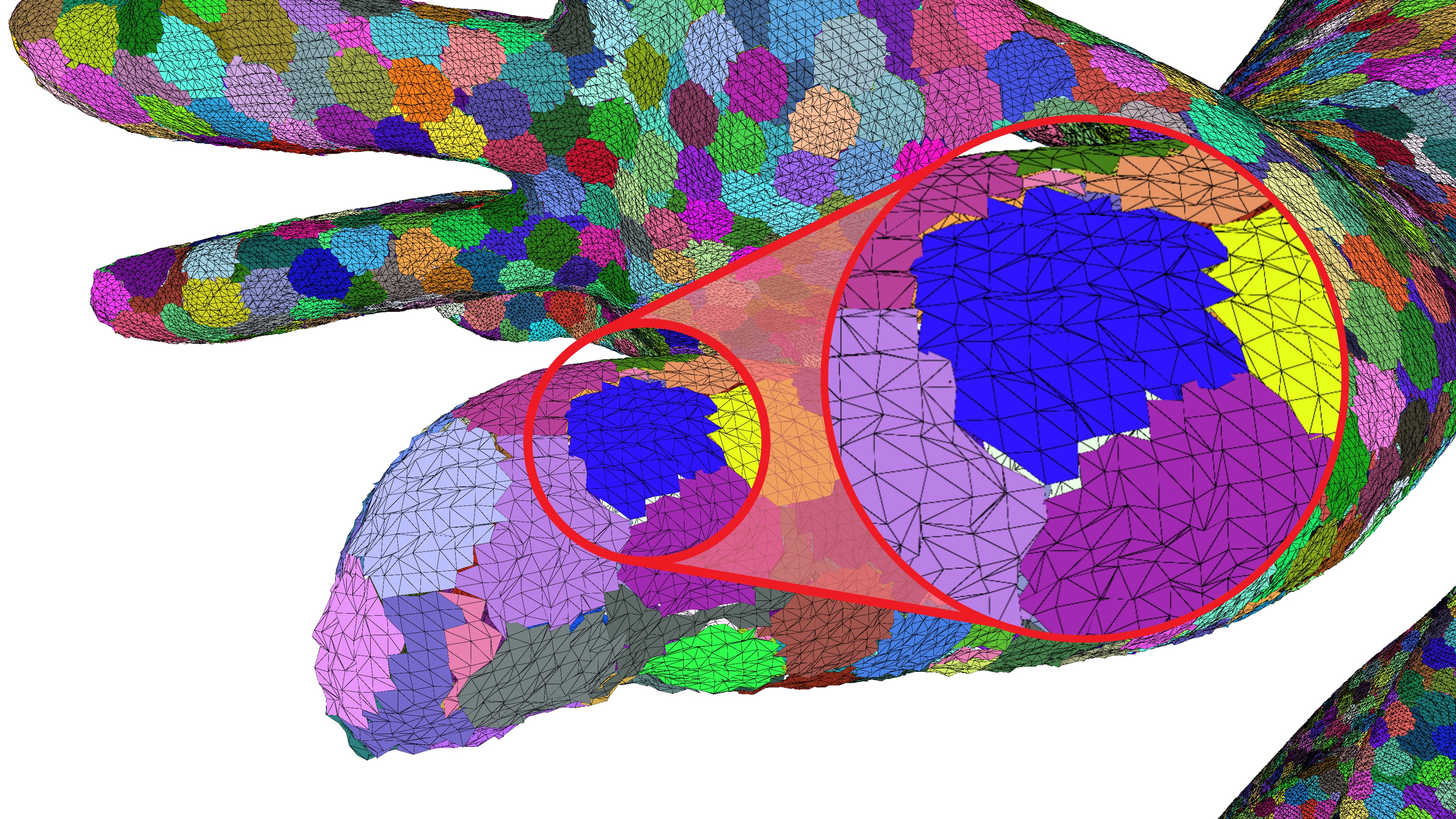
To fix this, we can define a global quantization grid that is adopted by the local quantization. In order to compute this global quantization grid, we first need to find the largest meshlet bounding box along a single axis. In this example, we’re only quantizing the x-axis component of the vertex positions, but the same logic can be applied to any set of floating-point values.
// Our mesh already contains the geometry as meshlets.// Each meshlet contains its own set of vertices that are not shared with any other meshlet.const auto& mesh = ...;
// Target precision for storing quantized values.// All meshlet will require at most 16 bits to store the quantized information.const auto targetBits = 16;
// Here we show quantization of the x-axis// The same process has to be applied to all other axes, including other floating-point attributes,// such as normals or texture coordinatesconst float globalMin   = mesh.GetAABB().min.x;const float globalDelta = mesh.GetAABB().max.x - globalMin;
// First we find the largest meshlet along the x-axisfloat largestMeshletDelta = 0.f;
for (const auto& meshlet : mesh.GetMeshlets()) {    const float meshletDelta = meshlet.GetAABB().max.x - meshlet.GetAABB().min.x;
    largestMeshletDelta = std::max(largestMeshletDelta, meshletDelta);}
With the bounding box, or rather the extents of the largest meshlet, we can compute the spacing between two quantized values on the meshlet-local grid and thus also the mesh-global quantization grid.
// Next we compute the local quantization spacing between two quantized values// when quantizing the largest meshlet to targetBits.const float         meshletQuantizationStep  = largestMeshletDelta / ((1 << targetBits) - 1);// This spacing will then be used to compute the number of quantized values in the global quantization grid.const std::uint32_t globalQuantizationStates = globalDelta / meshletQuantizationStep;
// Effective bit precision of quantized values.// If largestMeshletDelta is smaller than globalDelta, then this precision will be greater than targetBits.const float effectiveBits = std::log2(globalQuantizationStates);
// Global factors for en/decoding quantized valuesconst float quantizationFactor   = (globalQuantizationStates - 1) / globalDelta;// Explicit computation of dequantization factor is more precise than 1 / quantizationFactorconst float dequantizationFactor = globalDelta / (globalQuantizationStates - 1);
Depending on the ratio between the bounding box of the mesh and the bounding box of the largest meshlet, the effective precision of the mesh-global quantization grid can be greater than the initial target of 16 bits. For example, the x-axis of the Rock mesh in the teaser image has an effective precision of 17.6 bits.
Next, we can encode all the vertex positions using the quantizationFactor that we computed earlier.
To ensure a crack-free dequantization, we employ the following trick:
We first compute the meshlet offset on the mesh-global quantization grid.
We can then quantize the vertex position to the mesh-global quantization grid.
Next, we subtract this quantized meshlet offset, to ensure our quantized values do not exceed the 16-bit value range.
This conversion between the mesh-global and meshlet-local quantization grid can easily be reversed without introducing any floating-point errors.
// Encode all x-axis positions for all meshletsfor (const auto& meshlet : mesh.GetMeshlets()) {    // The quantized meshlet offset maps mesh-global quantized values onto    // meshlet-local quantization grid    const std::uint32_t quantizedMeshletOffset = static_cast<std::uint32_t>(        (meshlet.GetAABB().min.x - globalMin) * quantizationFactor + 0.5f);
    for (const auto& vertex : meshlet.GetVertices()) {        // Encode x-axis value, repeat for all other values        const float value = vertex.x;
        // First quantize value on global grid        const std::uint32_t globalQuantizedValue = static_cast<std::uint32_t>(            (value - globalMin) * quantizationFactor + 0.5f);        // Then move quantized value to local grid to keep within [0, (1 << targetBits) - 1] range        const std::uint32_t localQuantizedValue  = globalQuantizedValue - quantizedMeshletOffset;
        // Store local quantized value        ...    }
    // Store quantizedMeshletOffset per axis for each meshlet    ...}
// Store dequantizationFactor & globalMin per axis for dequantization...
To dequantize the values in the mesh shader, we need to pass the dequantizationFactor, globalMin and - for each meshlet - the quantizedMeshletOffset.
With these values the vertex position can be dequantized as follows:
const float value = (quantizedMeshletOffset + localQuantizedValue) * dequantizationFactor + globalMin;In this section, we optimize our renderer by performing meshlet culling in an amplification shader.
When we add an amplification shader to our pipeline, DispatchMesh changes from launching mesh shader thread groups to launching amplification shader thread groups.
In the following code example, we load the culling information relevant to the current meshlet and compute wether the meshlet is visible.
Note how we use WavePrefixCountBits to assign new indices to visible meshlets in the thread group.
After that WaveActiveCountBits returns the total number of visible meshlets in the group, required for calling DispatchMesh.
In our custom payload we specify the instance and meshlet id to be used in the mesh shader.
struct Payload {    uint2 meshletData[32];};
groupshared Payload payload;
[NumThreads(32, 1, 1)]void AmplificationShader(uint2 dtid : SV_DispatchThreadID){    // Amplification is dispatched with DispatchMesh((meshletCount + 31) / 32, instanceCount, 1);    const uint meshletId = dtid.x;    const uint instance  = dtid.y;
    bool visible = false;
    if (instance < RootConst.instanceCount)    {        visible = IsMeshletVisible(Meshlets[meshletId], instance);    }
    if (visible)    {        const uint index = WavePrefixCountBits(visible);        payload.meshletData[index] = uint2(meshletId, instance);    }
    const uint meshletCount = WaveActiveCountBits(visible);    DispatchMesh(meshletCount, 1, 1, payload);}
Frustum culling operates by creating a bounding volume around each meshlet - a simple shape that completely encloses the meshlet’s geometry. The meshlet’s bounding volume is then tested against the six planes that define the camera’s view frustum. If the bounding volume does not intersect with the frustum, the meshlet is considered outside the camera’s view and is culled, meaning it is not sent to the mesh shader.
Similar to hardware-accelerated back-face culling on a triangle by triangle level, it can be checked if all triangles of a meshlet face away from the camera. To achieve this, a bounding volume is necessary that encompasses all the normals of the faces within a meshlet. A practical choice for this volume is a cone, defined by a central normal vector and an opening angle. This cone represents the range of directions that the meshlet’s faces can be oriented in. While approximating this cone should work fine in most cases, finding the optimal cone is the same problem as the finding the smallest circle around a set of points.
In this section, we discuss the results of our compression technique. Our baseline mesh shading pipeline without compression uses 8 bit indices and the original vertex attributes.
We first compare the sizes of the index and vertex buffer of the vertex pipeline with the sizes for different combinations of mesh shading pipelines. The data size of the mesh shading pipeline includes the vertex buffer with duplicated vertices at a meshlet boundary, as well as the local index buffer and the offset buffer for storing meshlet meta information.
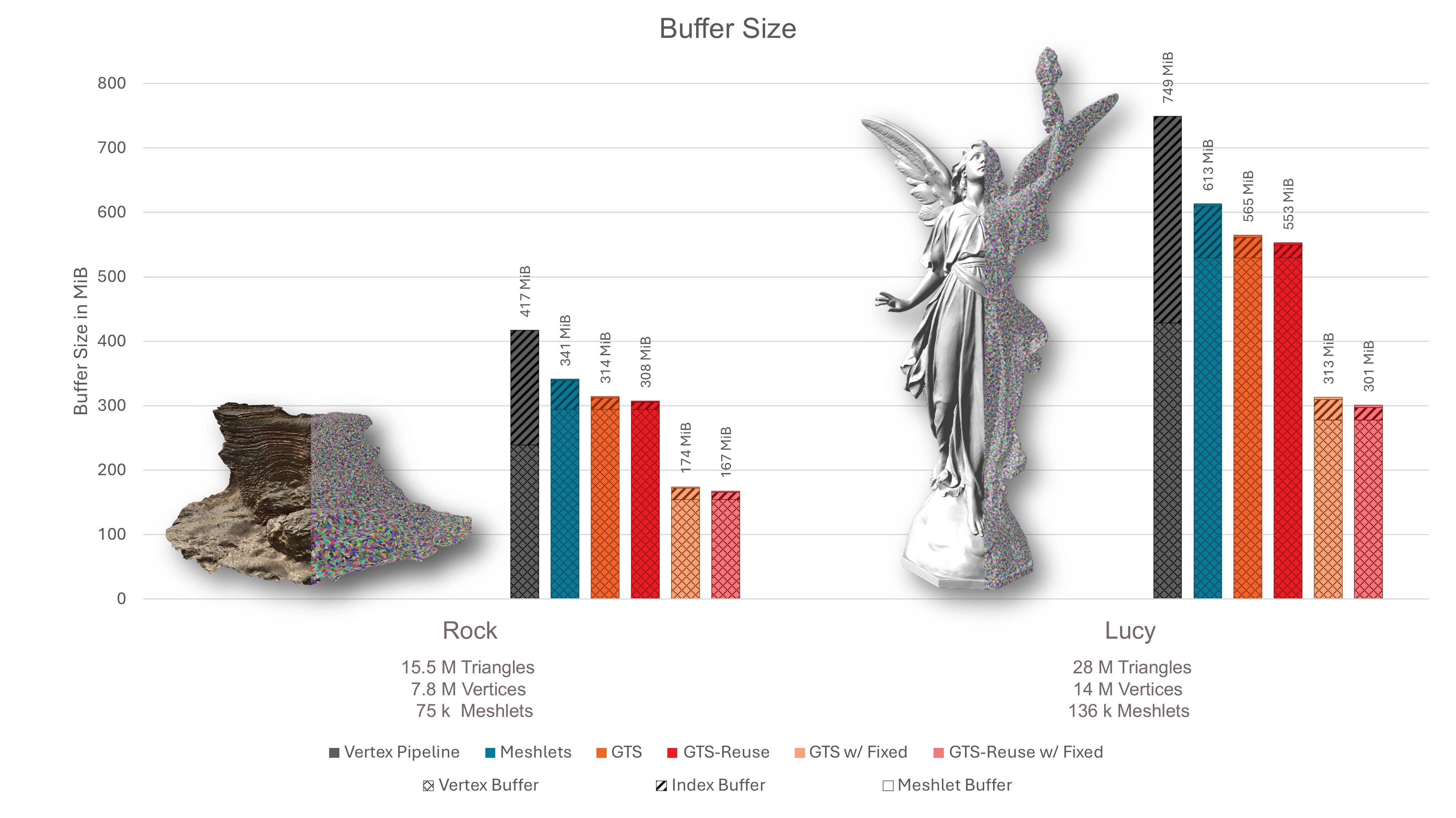
As can be seen, using the baseline mesh shader already achieves a compression compared to the vertex pipeline, because the reduction from 32 to 8 bit indices outweighs the required duplication of attributes. By further packing the triangles in a Generalized Triangle Strip, the indices are compressed with a ratio of ∼4:1 compared to the meshlet baseline, or ∼16:1 compared to the vertex pipeline. Thus, after compression, the index buffer becomes a negligible quantity compared to the size of the quantized vertex buffer. Note that we used a very conservative quantization of vertex attributes. Much higher vertex attribute compression ratios can still appear without loss iin visual quality.
The next figure shows our absolute rendering performance measurements. To emphasize the performance impact of the geometry stage, our Direct3D12 implementation renders to a 500 by 500 pixel framebuffer using Phong Shading. Note that by adding more complex shading, the performance impact of the geometry stage on the total render-time will decrease. As to be expected, the render-time grows linearly with the mesh size. As can be seen, our baseline mesh shader pipeline outperforms the vertex pipeline.
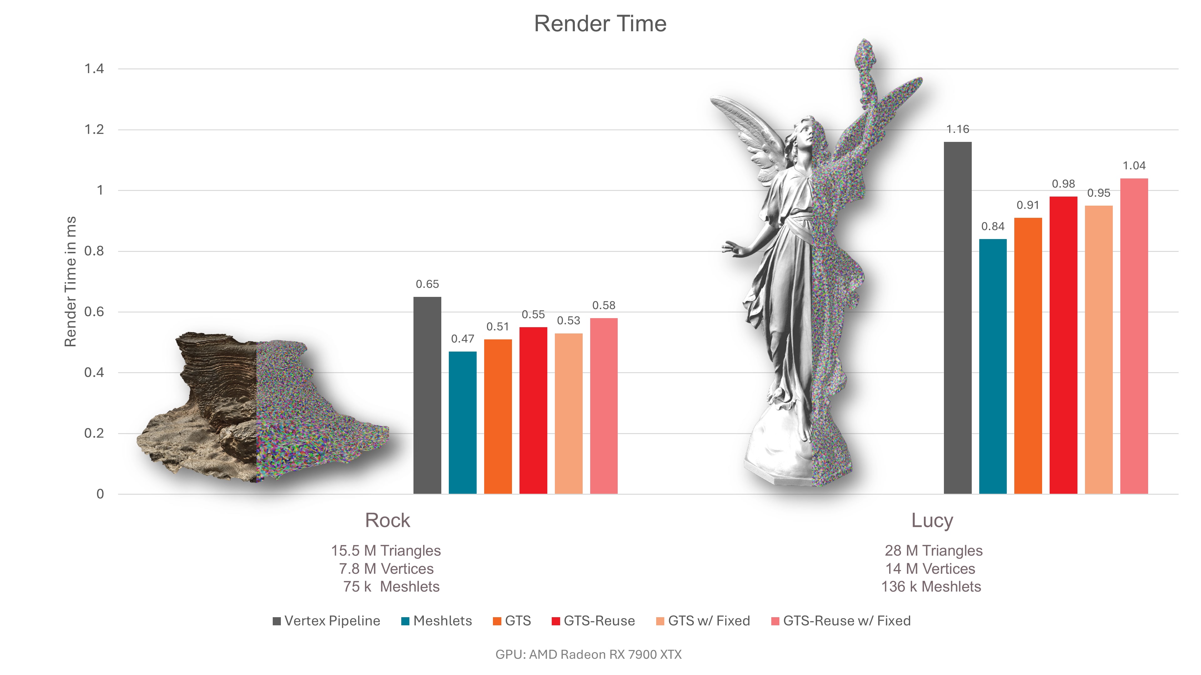
When adding decompression to the baseline, performance generally declines. This is not necessarily the case for the hairball mesh, which is bound by pixel overdraw.
The next figure is the same measurement, but with cone culling enabled. As, on average, every second meshlet faces away from the camera, the performance can improve by up to a factor of two. However, this does not work for our rock mesh, as almost all meshlets face towards the camera.
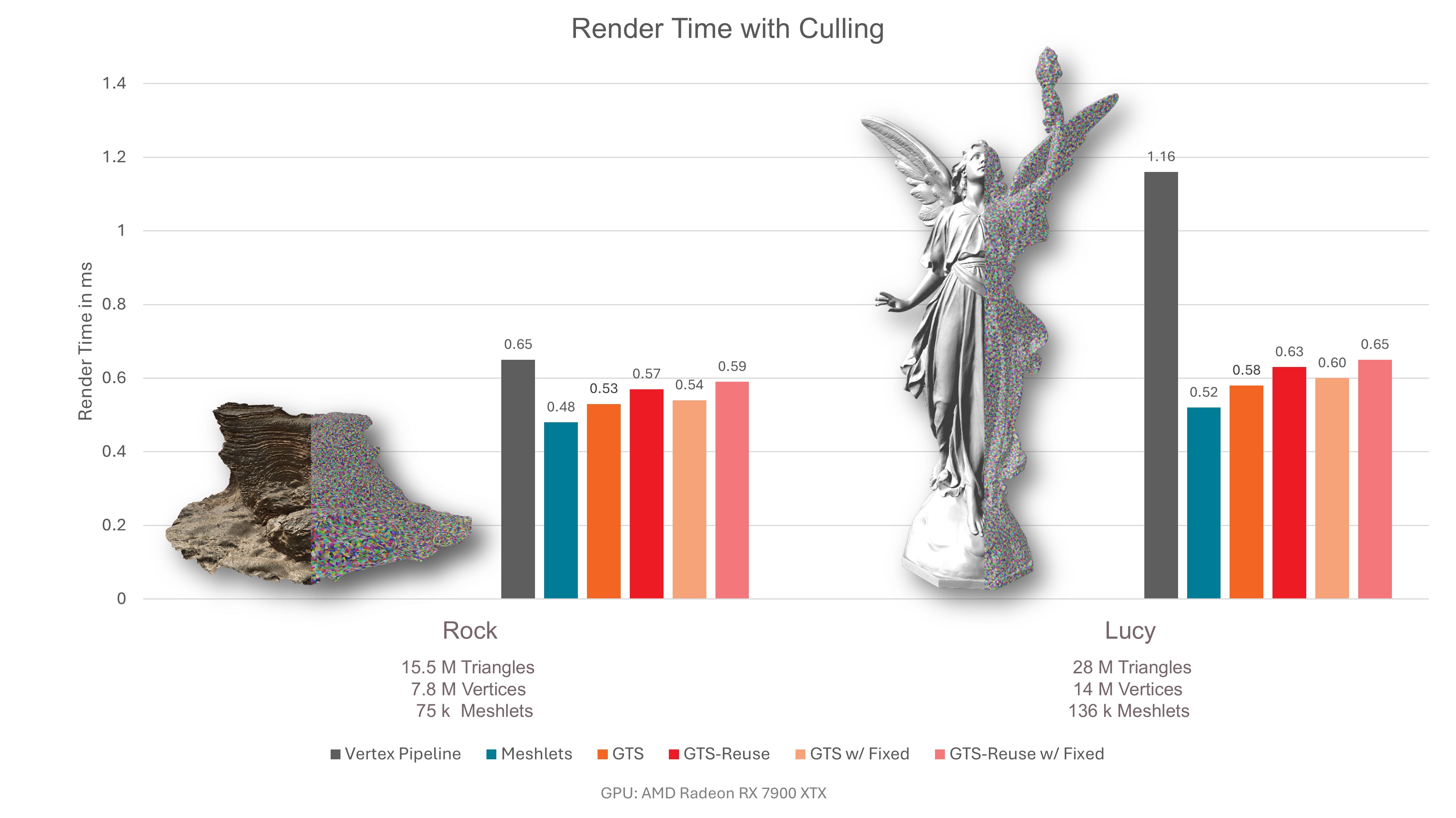
We hope this case study gave you some inspiration on how a mesh shader based geometry pipeline can be utilized to reduce the memory footprint of your application. At the same time mesh shaders have the ability to outperform the vertex pipeline in terms of speed, too. It is a win-win: Speed is increased, memory is reduced.
We were thrilled and honored to receive the Best Paper award at GCPR VMV 2024 for our paper “Towards Practical Meshlet Compression”.
Links to third-party sites are provided for convenience and unless explicitly stated, AMD is not responsible for the contents of such linked sites, and no endorsement is implied. GD-98
Microsoft is a registered trademark of Microsoft Corporation in the US and/or other countries. Other product names used in this publication are for identification purposes only and may be trademarks of their respective owners.
DirectX is a registered trademark of Microsoft Corporation in the US and/or other countries.


