Vulkan® Memory Allocator
VMA is our single-header, MIT-licensed, C++ library for easily and efficiently managing memory allocation for your Vulkan® games and applications.
Vulkan®’s barrier system is unique as it not only requires you to provide what resources are transitioning, but also specify a source and destination pipeline stage. This allows for more fine-grained control of when a transition is executed. However, you can also leave quite some performance on the table if you just use the simple way, so today we’re going to look at vkCmdPipelineBarrier in detail.
It is common knowledge that the GPU is a highly pipelined device. Commands come in at the top, and then individual stages like vertex and fragment shading are executed in order. Finally, commands retire at the bottom of the pipeline when execution has finished.
This is exposed in Vulkan® through the VK_PIPELINE_STAGE enumeration, which is defined as:
TOP_OF_PIPE_BIT
DRAW_INDIRECT_BIT
VERTEX_INPUT_BIT
VERTEX_SHADER_BIT
TESSELLATION_CONTROL_SHADER_BIT
TESSELLATION_EVALUATION_SHADER_BIT
GEOMETRY_SHADER_BIT
FRAGMENT_SHADER_BIT
EARLY_FRAGMENT_TESTS_BIT
LATE_FRAGMENT_TESTS_BIT
COLOR_ATTACHMENT_OUTPUT_BIT
TRANSFER_BIT
COMPUTE_SHADER_BIT
BOTTOM_OF_PIPE_BIT
Notice that this enumeration is not necessarily in the order a command is executed – some stages can be merged, some stages can be missing, but overall these are the pipeline stages a command will go through.
There are also three pseudo-stages which combine multiple stages or handle special access:
HOST_BIT
ALL_GRAPHICS_BIT
ALL_COMMANDS_BIT
For the sake of this article, the list between TOP_OF_PIPE_BIT and BOTTOM_OF_PIPE_BIT is what we’re going to discuss. So what does source and target mean in the context of a barrier? You can think of it as the “producer” and the “consumer” stage – the source being the producer, and the target stage being the consumer. By specifying the source and target stages, you tell the driver what operations need to finish before the transition can execute, and what must not have started yet.
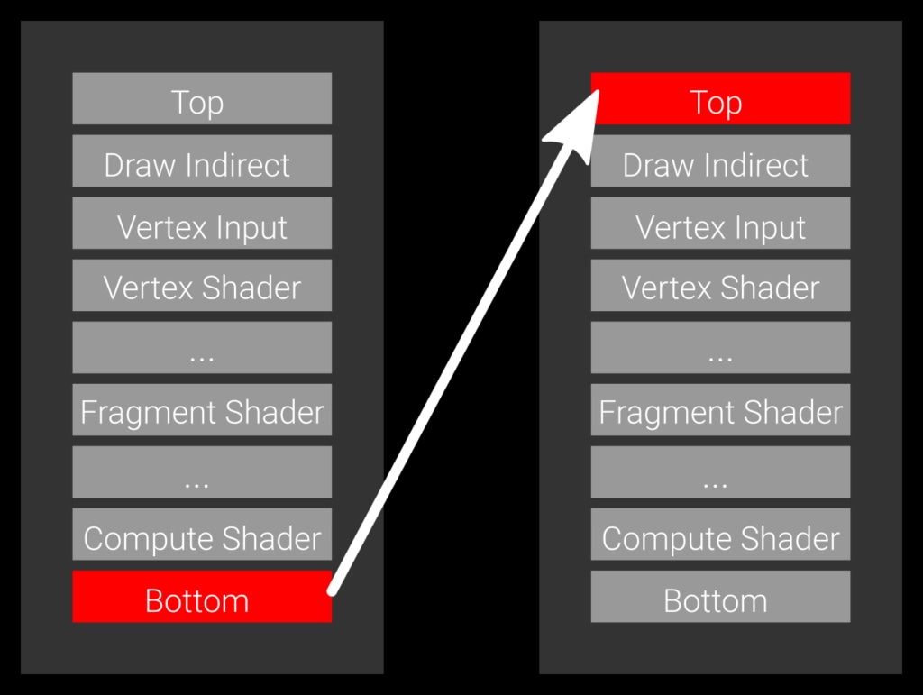
Example 1: a slow barrier, specifying the bottom of the pipe as the source stage and the top of pipe as the target stage.
Let’s look first at the simplest case, which is a barrier which specifies BOTTOM_OF_PIPE_BIT as the source stage and TOP_OF_PIPE_BIT as the target stage (Example 1). The source code for this would be something like:
vkCmdPipelineBarrier( commandBuffer, VK_PIPELINE_STAGE_BOTTOM_OF_PIPE_BIT, // source stage VK_PIPELINE_STAGE_TOP_OF_PIPE_BIT, // destination stage /* remaining parameters omitted */);This transition expresses that every command currently in flight on the GPU needs to finish, then the transition is executed, and no command may start before it finishes transitioning. This barrier will wait for everything to finish and block any work from starting. That’s generally not ideal because it introduces an unnecessary pipeline bubble.
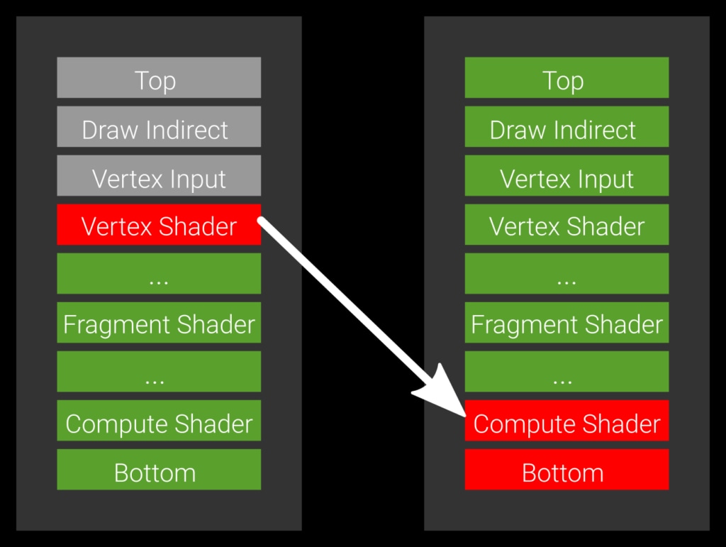
Example 2: the optimal barrier which allows all green pipeline stages to execute.
Imagine you have a vertex shader that also stores data via an imageStore and a compute shader that wants to consume it. In this case you wouldn’t want to wait for a subsequent fragment shader to finish as this can take a long time to complete. You really want the compute shader to start as soon as the vertex shader is done. The way to express this is to set the source stage -the producer- to VERTEX_SHADER_BIT and the target stage -the consumer- to COMPUTE_SHADER_BIT (Example 2).
vkCmdPipelineBarrier( commandBuffer, VK_PIPELINE_VERTEX_SHADER_BIT, // source stage VK_PIPELINE_COMPUTE_SHADER_BIT, // destination stage /* remaining parameters omitted */);If you write to a render target and read from it in a fragment shader, the stages would be VK_PIPELINE_STAGE_COLOR_ATTACHMENT_OUTPUT_BIT as the source and VK_PIPELINE_STAGE_FRAGMENT_SHADER_BIT as the destination – typical for G-Buffer rendering. For shadow maps, the source would be VK_PIPELINE_STAGE_LATE_FRAGMENT_TESTS_BIT. Another typical example is copying data – you produce the data through a copy, so the source stage would be set to VK_PIPELINE_STAGE_TRANSFER_BIT, and the destination to the stage where you need it. For vertex buffers, this would be for instance VK_PIPELINE_STAGE_VERTEX_INPUT_BIT.
Generally, you should try to maximize the number of “unblocked” stages, that is, produce data early and wait late for it. It’s always safe on the producer side to move towards the bottom of the pipe, as you’ll wait for more and more stages to finish, but it won’t improve performance. Similarly, if you want to be safe on the target side, you move upwards towards the top of pipe – but it prevents more stages from running, so that should be avoided as well.
One final remark: as mentioned previously, the hardware may not have all the stages internally, or may not be able to signal or wait at the specified stage. In those cases, the driver is free to move your source stage towards the bottom of the pipe and the target stage towards the top. This is implementation-specific though, and you should not have to worry about this – your goal should be to set the stages as “tight” as possible and minimize the number the blocked stages.