The BLAS windows
These panes show information about a bottom-level acceleration structure.
The BLAS Viewer
This pane is very similar to the TLAS viewer, except the leaf nodes are triangles instead of instances.
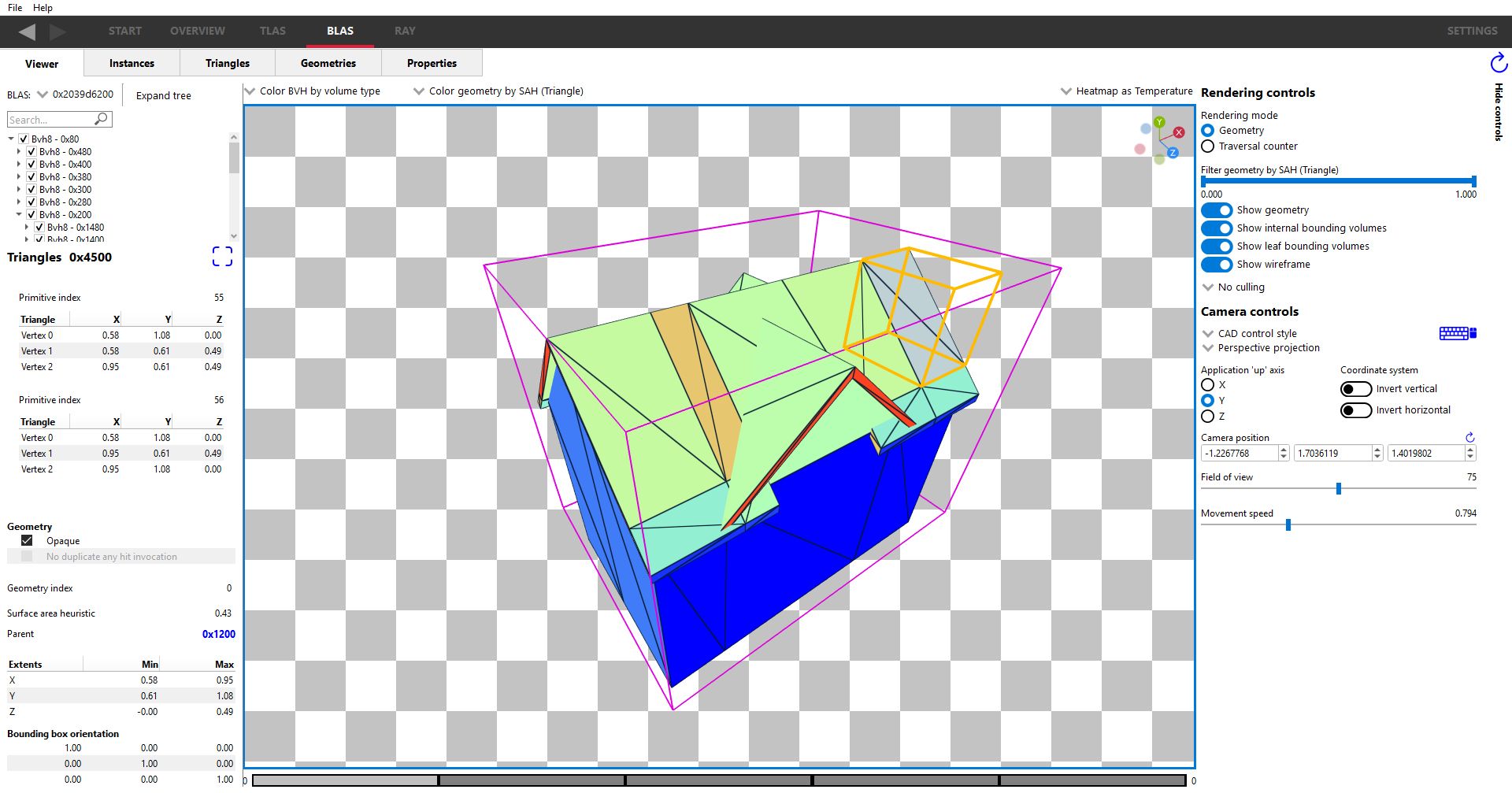
The most commonly used widgets are available in a row below the pane tabs.
- The BLAS dropdown allows selection of which BLAS to view.
- BVH Coloring allows the bounding volume wireframes to be painted depending on a number of different parameters. See the TLAS documentation for more details on these coloring modes.
- Geometry coloring allows the scene to be painted depending on a number of different parameters. The list of coloring modes is a subset used by the TLAS geometry modes combo box. See the TLAS documentation for more details on these coloring modes.
- Heatmap selection allows changing the color scheme of the heatmap. See the TLAS documentation for more details on these coloring modes.
On the left will be information for the bottom level acceleration structure:
- The treeview under the dropdown will show the structure of the BLAS. As seen here,
the topmost level contains a Box32 structure. This Box32 contains 4 more Box32
structures. The currently opened box shows a list of triangles inside this box.
Some BLASes may use node packing, where multiple bounding boxes reference
one shared subtree. Packed nodes are marked
(packed)in the tree view. Additional references contain aReferenced subtreeentry that navigates to the primary occurrence. Selecting a packed node highlights its shared subtree and the other references. See node-packing-label for details. - The section below the treeview gives details about the currently selected node, including the surface area heuristic, and extents. For a node that uses node packing, the details section also displays Referenced by. This reports how many parent bounding-box slots reference the shared node.
- If the selected node is a Bvh8 node, the bounding box orientation matrix will be shown. Bounding boxes may be rotated to fit the geometry more compactly.
- If the selected node is a triangle node then the triangle vertex positions will be displayed, as well as geometry flags of the geometry that the triangle is a part of.
In the center is a rendering of the bounding volume and geometry contained within that volume. Please see the TLAS help section for more information since the control modes and functionality is similar to the TLAS scene display.
Similar to the TLAS viewer, mousing over geometry in the scene will show a tooltip indicating the numeric value of that triangle for the currently selected color mode.
It is possible to select individual triangles within the scene by clicking on a mesh within the viewport. The BLAS hierarchy tree view will expand as necessary to focus on the selected triangle node.
On the right are the same rendering and camera controls as seen in the TLAS pane; the functionality of these are nearly identical. The only difference is that there is no option to show instance transforms in the BLAS pane.
Culling mode ray flags
These work slightly differently to those in the TLAS pane, since at the BLAS level there is no concept of an instance. That means there are no instance flags to override the ray flags set up in the RRA user interface.
Triangle splitting
Triangle splitting is another driver optimization that can be used if a triangle isn’t axis aligned. This can result in a lot of empty space in the bounding volume. In this case, the triangle is split into smaller triangles, each with a smaller bounding volume. This reduces the triangle-area to bounding volume ratio.
It should be noted that all split triangles will share the same 3 triangle vertices, and parts of the triangle will lie outside of the split triangle bounding volume. This can be seen with geometry rendering (below).
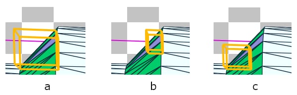
Image (a) Shows the bounding volume around the entire triangle geometry. Notice that this triangle is about 45 degrees to one of the axes; the unused space in the bounding volume can be clearly seen. Images (b) and (c) show the individual split triangles making up the triangle geometry in (a).
Since ray tracing deals with bounding volumes, only the part of the triangle inside the bounding volume will be considered. This can be seen with the traversal rendering, where only the area of the triangle inside the bounding volume is visible (below).
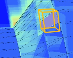
These 2 images are from the same scene, but seen from a slightly different angle.
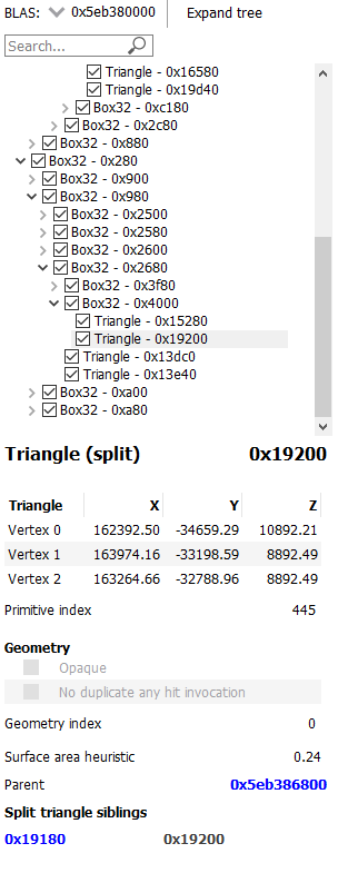
When a split triangle is selected, the left-side pane will indicate that the triangle is split, as seen below. A list of the split triangle siblings is also shown, allowing easy selection.
Cluster acceleration structures (CBLAS and CLAS)
Some traces use clustered geometry, which introduces two additional kinds of bottom-level acceleration structure that are also inspected in this pane:
-
A CBLAS (cluster bottom-level acceleration structure) does not contain triangles directly. Instead, its leaf nodes are instances that each reference a CLAS. In this respect a CBLAS behaves like a small TLAS that lives one level below the TLAS.
-
A CLAS (cluster-level acceleration structure) contains the actual triangle geometry, in the same way as an ordinary BLAS.
This forms a three-level hierarchy: the TLAS instances a CBLAS, the CBLAS instances one or more CLASes, and each CLAS contains triangles.
Because a CBLAS and a CLAS are both inspected using the BLAS Viewer, a label to the left of the acceleration-structure dropdown at the top of the pane indicates which kind of structure is currently being viewed. It reads BLAS:, CBLAS:, or CLAS: accordingly. For an ordinary trace with no clustered geometry, this label always reads BLAS:.
When a CBLAS is being viewed, the leaf nodes of the tree are cluster references
rather than triangles. Each cluster-reference leaf is labelled CLAS [id] and
shows the address of the referenced CLAS and its triangle count. Selecting a
cluster-reference leaf shows the instance mask and the world-to-object transform of
that CLAS reference in the panel below the tree, in place of the surface area
heuristic and triangle information shown for triangle nodes.
Double-clicking a cluster-reference leaf (or its geometry in the scene) descends into the referenced CLAS, which is then inspected in the same pane. A CLAS contains ordinary triangle geometry, so its tree ends in triangle leaves just like a regular BLAS. Navigation moves through the hierarchy one level at a time: double-clicking a CBLAS instance in the TLAS Viewer opens the CBLAS first, and from there a cluster-reference leaf opens the CLAS, so the full TLAS → CBLAS → CLAS path is walked step by step.
The BLAS Instances Tab
The Instances tab displays a read-only table of properties and statistics for instances of the selected BLAS.
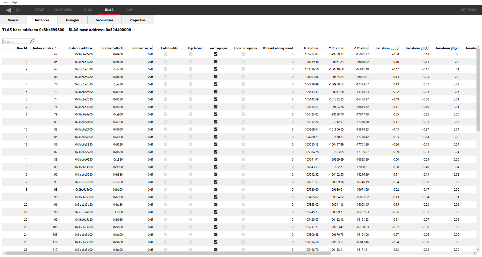
Above the table is the base address of the BLAS used by all the instances.
The following fields are displayed:
-
Row Id - The row index. This is an incrementing value starting at 0.
-
Instance index - The API index for the instance.
-
Instance address – The virtual GPU address for the instance node within the TLAS.
-
Instance offset – The relative address for the instance node with respect to the TLAS address.
-
Instance mask - The mask specified for the instance node determining which trace ray calls will interact with it.
-
Cull disable - Instance flag specifying if the cull mode is disabled.
-
Flip facing - Instance flag specifying whether the triangle front face should be inverted.
-
Force opaque - Instance flag specifying if this instance should be opaque regardless of geometry flags.
-
Force no opaque - Instance flag specifying if this instance should be non-opaque regardless of geometry flags.
-
Rebraid sibling count - If this instance was split into multiple instance nodes by the driver, this is how many sibling instance nodes this instance has.
-
X Position – The X-position of the instance in the scene.
-
Y Position – The Y-position of the instance in the scene.
-
Z Position – The Z-position of the instance in the scene.
-
Transform[x][y] - The instance transform, comprising of the rotation and scaling components.
The columns can be sorted by clicking on them. The arrow in the heading shows if sorting is in ascending or descending order. The Row Id cannot be sorted.
Typically, instances are created with their own local co-ordinate system. When placed in the scene, each instance requires a transformation from its local co-ordinate system to the world co-ordinate system. This is shown by the position and transform matrix in the table.
The Triangles Tab
The Triangles tab displays a read-only table of properties and statistics for triangle nodes in the selected BLAS.
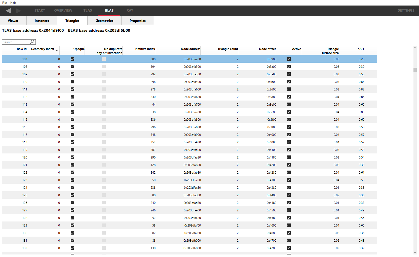
Above the table is the base address of the BLAS used by all the triangles, and the base address of the TLAS containing the BLAS.
The following fields are displayed:
-
Row Id - The row index. This is an incrementing value starting at 0.
-
Geometry index - The index of the geometry that the triangle belongs to.
-
Opaque - Presence of the opaque geometry flag.
-
No duplicate any hit invocation - Presence of the no duplicate any hit invocation geometry flag.
-
Primitive index - The API index of the triangle accessible in shaders.
-
Node address - The virtual address of this node in GPU memory.
-
Node offset - The relative address of this node relative to the BLAS address.
-
Active - Whether or not this triangle is active according to the API specification definition.
-
Triangle surface area - The surface area of the triangle node.
-
SAH - The surface area heuristic of the triangle node.
-
Vertex0 - The vertex position of the first triangle vertex.
-
Vertex1 - The vertex position of the second triangle vertex.
-
Vertex2 - The vertex position of the third triangle vertex.
The columns can be sorted by clicking on the column header, apart from the vertex columns; sorting is disabled for these columns. The arrow in the heading shows if sorting is in ascending or descending order. The Row Id cannot be sorted.
The Geometries Tab
The Geometries tab displays a read-only table of properties and statistics for the geometries in the selected BLAS.
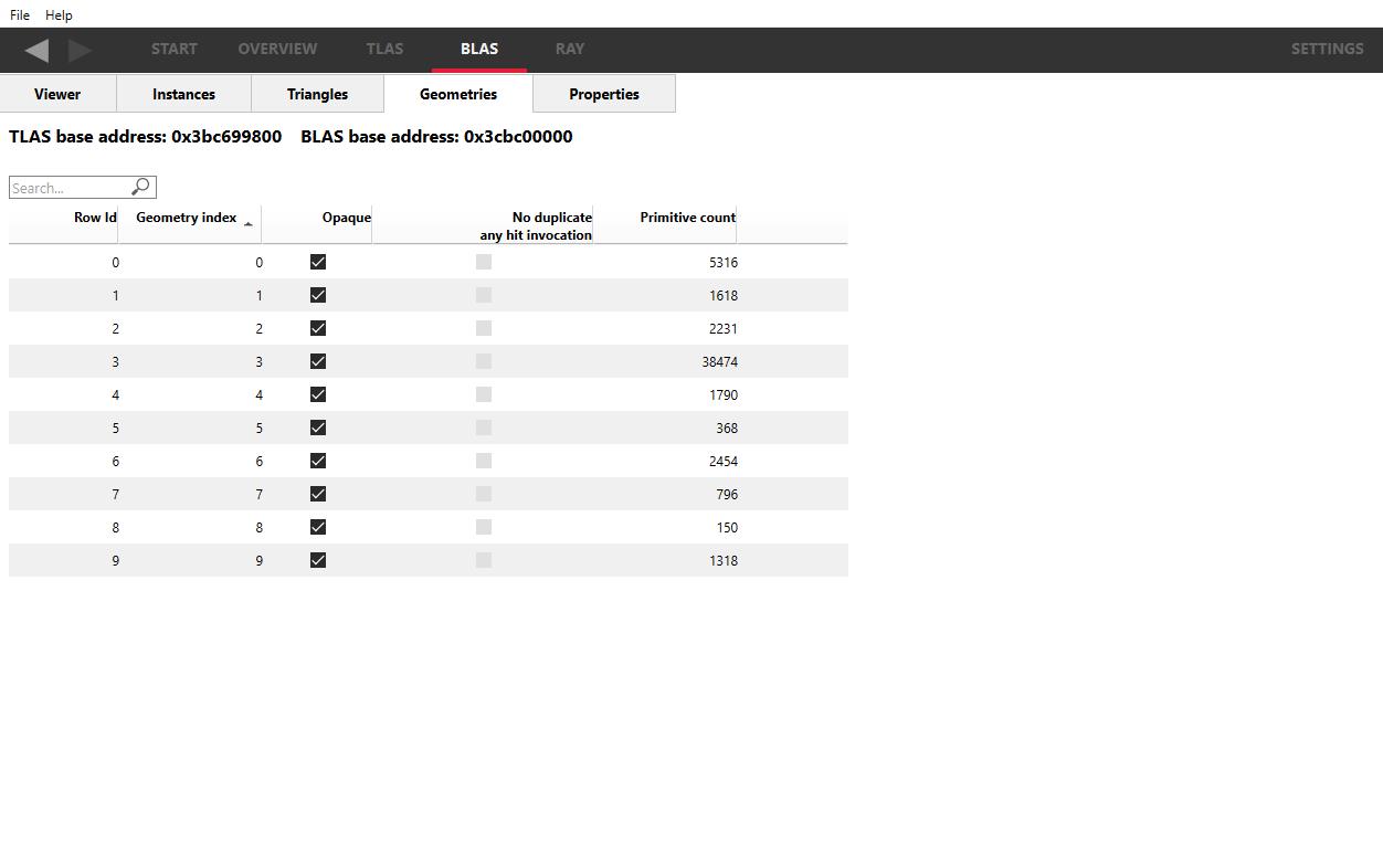
Above the table is the base address of the BLAS used by all the geometries, and the base address of the TLAS containing the BLAS.
The following fields are displayed:
-
Row Id - The row index. This is an incrementing value starting at 0.
-
Geometry index - The index of the geometry in the BLAS. This refers to the first column in the triangles table.
-
Opaque - Presence of the opaque geometry flag.
-
No duplicate any hit invocation - Presence of the no duplicate any hit invocation geometry flag.
-
Primitive count - The number of primitives contained in the geometry.
The columns can be sorted by clicking on the column header. The arrow in the heading shows if sorting is in ascending or descending order. The Row Id cannot be sorted.
The BLAS Properties Tab
The Properties tab displays a read-only table of properties and statistics for the selected BLAS.
