AMD FidelityFX™ Variable Shading
AMD FidelityFX Variable Shading drives Variable Rate Shading into your game.
To get started with mesh nodes, you’ll first need a Microsoft Agility SDK and Microsoft DirectX® shader compiler that support mesh nodes. You can find a download link for both in Microsoft’s own announcement blog post.
You will also need a graphics card that supports mesh nodes (an AMD Radeon™ RX 7000 or 9000 Series Graphics Card) and an AMD driver with mesh nodes support, which you can find here.
In order to enable Mesh Nodes functionality in Work Graphs on Adrenalin drivers, the following registry key (as REG_SZ) needs to be set:
HKEY_LOCAL_MACHINE\SYSTEM\ControlSet001\Control\Class\{4d36e968-e325-11ce-bfc1-08002be10318}\0000\UMD\DXC\#3226567005=1
Note that the
\0000\may be a larger number depending on how many video cards you have enabled on your machine, or how many driver updates have been installed. If you have multiple numbered subkeys under{4d36e968-e325-11ce-bfc1-08002be10318}be sure to set#3226567005to1for each subkey that is present.
As mesh nodes are currently an experimental preview feature, you’ll also need to enable the Developer Mode in Windows.
Note: This getting started guide focuses on the new mesh node feature of GPU work graphs in DirectX® 12. If you are not already comfortable with DirectX® 12, work graphs, or mesh shaders, you may wish to learn more by reading up on these topics before continuing:
This blog post describes the usage of mesh nodes in the HelloMeshNodes sample. The HelloMeshNodes sample itself is a combination of the work graphs part from the already existing HelloWorkGraphs sample and the window, swapchain, and main loop from Microsoft’s D3D12 HelloTriangle sample.
The work graph of HelloMeshNodes contains two compute nodes and two mesh nodes, which recursively evaluate and render the Koch snowflake fractal.

In the following sections, we’ll walk through step-by-step over everything that is needed to use mesh nodes inside a work graph.
As we updated the Microsoft Agility SDK to 1.715.0-preview, we also need to update the D3D12SDKVersion export.
extern "C" { __declspec(dllexport) extern const UINT D3D12SDKVersion = 715; } // or laterMesh nodes also require experimental state object features and the experimental shader model 6.9, thus we need to enable these experimental features before creating our ID3D12Device.
UUID ExperimentalFeatures[2] = { D3D12ExperimentalShaderModels, D3D12StateObjectsExperiment };HRESULT hr = D3D12EnableExperimentalFeatures(_countof(ExperimentalFeatures), ExperimentalFeatures, nullptr, nullptr);Mesh nodes are part of the work graphs 1.1 feature set, and once we have successfully created our ID3D12Device, we need to check if it supports this work graphs tier.
We can use the D3D12_FEATURE_D3D12_OPTIONS21 to check if the supported tier is at least D3D12_WORK_GRAPHS_TIER_1_1.
D3D12_FEATURE_DATA_D3D12_OPTIONS21 options = {};device->CheckFeatureSupport(D3D12_FEATURE_D3D12_OPTIONS21, &options, sizeof(options));
return (options.WorkGraphsTier >= D3D12_WORK_GRAPHS_TIER_1_1);Similar to how we can turn any compute kernel into a work graph node, we can do the same with any mesh shader, by adding a few HLSL attributes to it. The resulting syntax is a mixture of the already existing mesh shader attributes and the new mesh node attributes. As an example, we’ll take a look at the following mesh node declaration:
[Shader("node")][NodeLaunch("mesh")][NodeDispatchGrid(1, 1, 1)][NodeId("LineMeshNode", 0)][NumThreads(32, 1, 1)][OutputTopology("triangle")]void LineMeshShader( uint gtid : SV_GroupThreadId, DispatchNodeInputRecord<LineRecord> inputRecord, out indices uint3 triangles[4], out primitives Primitive prims[4], out vertices Vertex verts[6])[Shader("node")]: indicates that this function will be used in a work graph.[NodeLaunch("mesh")]: indicates that this function will be a mesh node.[NodeDispatchGrid(1, 1, 1)]: Mesh nodes behave similar to broadcasting nodes, in that they can either define a fixed dispatch grid of mesh shader thread groups to be launched each time this node is invoked, or define limits for a dynamic dispatch grid with the [NodeMaxDispatchGrid(x, y, z)] attribute.uint/uint2/uint3 with the SV_DispatchGrid semantic in the input record. The maximum size of the dispatch grid is limited by the same limits as broadcasting nodes.[NodeId("LineMeshNode", 0)]: Specifies the node id with which this node will be referenced in the work graph. The node array index is not required and will default to 0 if not explicitly defined otherwise.NodeId attribute is specified, the mesh shader function name will be used instead. Alternatively, the mesh node id can also be set when creating the work graph using an override. This can be used to create multiple different mesh nodes from the same mesh shader.[NumThreads(32, 1, 1)]: defines the three-dimensional grid of threads inside the mesh shader thread group. As in this case, we are defining a mesh shader, the total number of threads in a thread group is limited to 128 (see mesh shader specification).[OutputTopology("triangle")]: Mandatory attribute for mesh shaders that defines the topology of output primitives (see mesh shader specification).LineMeshShader: Export name of our mesh shader function. We’ll need this later on to define a generic program and turn this function into a full mesh shader pipeline. Unless you’re using export overrides for your shader libraries, this name needs to be unique across the entire work graph.
Additionally, if no [NodeId(...)] attribute is defined, this function name will be used as the node id.DispatchNodeInputRecord<LineRecord> inputRecord: Similar to broadcasting nodes, this defines the input record to the mesh node and replaces the previous mesh payload syntax used with amplification shaders. Amplification shaders cannot be used in combination with work graphs/mesh nodes.out indices, out primitives and out vertices arguments, compared to conventional mesh shaders.Amplification shaders are not supported for mesh nodes, but you can easily rewrite any existing amplification shader implementation as a broadcasting node to achieve the same functionality.
To summarize, other than the work graph specific attributes and the slightly different syntax for receiving an input payload, the working principle of mesh shaders remains unchanged. You can find more information on the inner workings of mesh shaders, best practices for writing them, and some example use cases in our mesh shader blog post series. With mesh nodes, you can also define resource bindings to your mesh shader through local root signature. This might come in handy when combining multiple existing mesh shaders with different resource bindings into the same work graph.
Pixel shaders can be written in the same way as with normal mesh shader pipelines - or omitted in the case of, e.g., depth-only shadow passes. Pixel shaders cannot access the input record of the mesh shader, so any data required for shading (e.g. material ID) must be passed through either vertex or primitive attributes.
float4 MeshNodePixelShader(in float4 color : COLOR0) : SV_TARGET{ return color;}Pixel shaders can still be located in the same file as the mesh shader or other nodes, but they will be ignored when compiling using the lib_6_* targets, so they need to be compiled separately.
Now that we’ve declared our first mesh node and all of its attributes, we can send records to it from any compute node in our work graph.
Additionally, we can also send graph entry records.
The syntax for sending a record to a mesh node is the same as with any other node.
In this example, we have a thread launch entry node which is invoking our LineMeshNode node to draw a line across the screen.
[Shader("node")][NodeLaunch("thread")]void MyComputeNode(    [MaxRecords(1)]    [NodeId("LineMeshNode", 0)]    NodeOutput<LineRecord> meshNodeOutput) {    ThreadNodeOutputRecords<LineRecord> outputRecord = meshNodeOutput.GetThreadNodeOutputRecords(1);
    outputRecord.Get().start = float2(-1, 0);    outputRecord.Get().end   = float2( 1, 0);
outputRecord.OutputComplete();}Note: This code only serves as an example for how to invoke mesh nodes. For optimal performance, we recommend launching larger mesh node workloads at a time. You can read more about this and other recommendations in the best practices section.
To make our shaders usable, we need to first compile them to the DirectX® Intermediate Language (DXIL) using the DirectX® Shader Compiler.
This can be done offline or at runtime using the IDxcCompiler interface.
In the HelloMeshNodes sample, compiling shaders is handled by the CompileShader function and you can find the full source code for it here.
ID3DBlob* CompileShader(const std::string& shaderCode, const wchar_t* entryPoint, const wchar_t* targetProfile);The support for mesh nodes and the [NodeLaunch("mesh")] attribute are only available in shader model 6.9 and onwards, so we need to compile our shader library as lib_6_9.
As mentioned before, pixel shaders are not included when compiling the shaders with lib_6_9, so we need to compile the shader source code again separately with the ps_6_9 target and specify the entry point as our MeshNodePixelShader function from above.
// Contains mesh nodes (i.e., mesh shaders with node attributes) and all other compute nodesCComPtr<ID3DBlob> workGraphBlob = CompileShader(shaderSourceCode, nullptr, L"lib_6_9");// Contains pixel shader for mesh nodesCComPtr<ID3DBlob> pixelShaderBlob = CompileShader(shaderSourceCode, L"MeshNodePixelShader", L"ps_6_9");With all the shader code written and compiled, we can turn our attention to creating a work graph state object with mesh nodes.
Creating the work graph state object with mesh nodes is in large parts the same as before and we’ll skip over most of the steps here and only focus on mesh node specific changes.
CD3DX12_STATE_OBJECT_DESC stateObjectDesc(D3D12_STATE_OBJECT_TYPE_EXECUTABLE);We can use the IncludeAllAvailableNodes() function or D3D12_WORK_GRAPH_FLAG_INCLUDE_ALL_AVAILABLE_NODES flag to enable auto-population of all available nodes into our work graph.
We’ll see later on how this auto-population interacts with the new mesh nodes.
CD3DX12_WORK_GRAPH_SUBOBJECT* workGraphDesc = stateObjectDesc.CreateSubobject<CD3DX12_WORK_GRAPH_SUBOBJECT>();workGraphDesc->IncludeAllAvailableNodes();workGraphDesc->SetProgramName(ProgramName);A DirectX® 12 command list tracks resource bindings to shaders separately for compute pipelines (i.e., commandList->SetComputeRoot*(...)) and graphics pipelines (i.e., commandList->SetGraphicsRoot*(...)) with two separate root signatures.
Up until now, work graphs only consisted of compute nodes (i.e., compute shaders) and thus resource bindings were set through the compute root signature.
With the addition of mesh nodes, a work graph can now also contain graphics nodes, and thus when this is the case, the entire work graph must use the graphics root arguments for its global root signature and not the compute root arguments.
This is indicated by setting the WORK_GRAPHS_USE_GRAPHICS_STATE_FOR_GLOBAL_ROOT_SIGNATURE state object flag.
auto configSubobject = stateObjectDesc.CreateSubobject<CD3DX12_STATE_OBJECT_CONFIG_SUBOBJECT>();configSubobject->SetFlags(D3D12_STATE_OBJECT_FLAG_WORK_GRAPHS_USE_GRAPHICS_STATE_FOR_GLOBAL_ROOT_SIGNATURE);Of course, mesh nodes can - in contrast to regular mesh shaders - also use local root signatures in addition to the global root signature of the work graph.
The process of setting the local root arguments (for compute and mesh nodes) through the D3D12_SET_WORK_GRAPH_DESC and binding them to nodes through [NodeLocalRootArgumentsTableIndex()] remains unchanged.
Next, we can add the two binary shader blobs we compiled earlier to our work graph.
For the work graph library, i.e., the one compiled with lib_6_9, everything remains the same.
This will add all the regular compute nodes and the mesh nodes in our shader source to the state object.
{ CD3DX12_DXIL_LIBRARY_SUBOBJECT* libraryDesc = stateObjectDesc.CreateSubobject<CD3DX12_DXIL_LIBRARY_SUBOBJECT>(); CD3DX12_SHADER_BYTECODE libraryCode(workGraphBlob); libraryDesc->SetDXILLibrary(&libraryCode);}Next, we can add the pixel shader library in the same way.
This will add the MeshNodePixelShader pixel shader to our state object.
{ CD3DX12_DXIL_LIBRARY_SUBOBJECT* libraryDesc = stateObjectDesc.CreateSubobject<CD3DX12_DXIL_LIBRARY_SUBOBJECT>(); CD3DX12_SHADER_BYTECODE libraryCode(pixelShaderBlob); libraryDesc->SetDXILLibrary(&libraryCode);}Graphics pipelines do not only define the combination of shaders to be executed in the various pipeline stages, but also define additional state, such as render targets, rasterizer state, or blend state.
For mesh shaders, this state is set in the D3DX12_MESH_SHADER_PIPELINE_STATE_DESC description.
For mesh nodes, the process of setting both the mesh and pixel shader, as well as all the additional graphics pipeline state is done through generic programs.
Unlike the pipeline state description structs for graphics pipelines, which define the entire pipeline state in one struct, generic programs offer a modular approach to defining a graphics pipeline.
Each generic program in our work graph is defined by a CD3DX12_GENERIC_PROGRAM_SUBOBJECT in our state object description, to which we’ll add different shaders through exports and describe the pipeline state through a collection of other subobjects.
By default, each generic program subobject will auto-populate to a single mesh node in our work graph, if D3D12_WORK_GRAPH_FLAG_INCLUDE_ALL_AVAILABLE_NODES is set, but we can also use explicit node overrides to define multiple mesh nodes from the same generic program.
auto genericProgramSubobject = stateObjectDesc.CreateSubobject<CD3DX12_GENERIC_PROGRAM_SUBOBJECT>();As we’ve already added the binary shader code for both the mesh and pixel shader above, we can reference them by their export names and add them to the generic program subobject. In both cases, the export name is the function name of the respective shader. Each mesh or pixel shader can be referenced multiple times to build different mesh shader pipelines.
genericProgramSubobject->AddExport(L"LineMeshShader");genericProgramSubobject->AddExport(L"MeshNodePixelShader");To define the rest of the graphics pipeline state, such as render targets, rasterizer state, or blend state, we can add different subobjects to our generic program through genericProgramSubobject->AddSubobject(...);.
Each of these state-defining subobjects must also be contained within the state object description for our work graph.
As an example, we’ll add a CD3DX12_RENDER_TARGET_FORMATS_SUBOBJECT and define the render target format state based on our swapchain.
auto renderTargetFormatSubobject = stateObjectDesc.CreateSubobject<CD3DX12_RENDER_TARGET_FORMATS_SUBOBJECT>();renderTargetFormatSubobject->SetNumRenderTargets(1);renderTargetFormatSubobject->SetRenderTargetFormat(0, DXGI_FORMAT_R8G8B8A8_UNORM);Similar to the mesh and pixel shaders, these subobjects can be added to multiple different generic program subobjects within the same state object description. You can think of these as modular building blocks, with which you can assemble different graphics pipelines based on your needs.
Other “building blocks”, such as rasterizer-, blend-, or depth-stencil state can be created and configured in the same way. You can find a full list of the supported subobjects in generic programs here. If a generic program does not contain a subobject - or “building block” - for a particular part of the pipeline state, a default value is used instead.
Once we created all the “building blocks” for our generic program, we can add them as follows:
// Add "building blocks" to define the graphics pipeline state for our mesh nodegenericProgramSubobject->AddSubobject(*rasterizerSubobject);genericProgramSubobject->AddSubobject(*depthStencilSubobject);genericProgramSubobject->AddSubobject(*depthStencilFormatSubobject);genericProgramSubobject->AddSubobject(*renderTargetFormatSubobject);...With this, we successfully created a generic program for our mesh node.
As we set the D3D12_WORK_GRAPH_FLAG_INCLUDE_ALL_AVAILABLE_NODES through workGraphDesc->IncludeAllAvailableNodes();, this generic program will be automatically added to the work graph.
The node identifier for this node is defined by the [NodeId(...)] attribute of our mesh shader, or, if this attribute is not set, by the name of our mesh shader function.
Alternatively, we can also override the mesh node id, which we’ll look at in the next section.
If D3D12_WORK_GRAPH_FLAG_INCLUDE_ALL_AVAILABLE_NODES is not used, we have to explicitly add our mesh node to the work graph.
For mesh nodes, this is done with workGraphDesc->CreateProgramNode(...) and not workGraphDesc->CreateShaderNode(...), which is used for regular compute nodes.
In order to add our mesh node, we first need to name our generic program subobject. This name is purely for identification purposes and must be unique inside the state object description.
genericProgramSubobject->SetProgramName(L"TriangleMeshNodeGenericProgram");workGraphDesc->CreateProgramNode(L"TriangleMeshNodeGenericProgram");Alternatively, we can also specify a mesh node override, to add the mesh node to the graph.
Even if D3D12_WORK_GRAPH_FLAG_INCLUDE_ALL_AVAILABLE_NODES is used, mesh nodes can still be modified and renamed through mesh node overrides when creating the work graph.
This can be useful, if, e.g., the same mesh shader is used in multiple mesh nodes, and thus the auto-populated node id (either the function name or the [NodeId(...)] attribute) are no longer unique in the graph.
Similar to the explicit mesh nodes created through CreateProgramNode, we first need to give our generic program a unique name.
We can then create a mesh node override in the work graph description for that name.
With this override, we can set the node id and/or change other node attributes, such as the dispatch grid or input record sharing.
genericProgramSubobject->SetProgramName(L"TriangleMeshNodeGenericProgram");
auto nodeOverride = workGraphDesc->CreateMeshLaunchNodeOverrides(L"TriangleMeshNodeGenericProgram");nodeOverride->NewName({ L"TriangleMeshNode", 0 });
With the Agility SDK version 1.715.0-preview as well as version 1.614.1, the behavior of node overrides in combination with D3D12_WORK_GRAPH_FLAG_INCLUDE_ALL_AVAILABLE_NODES has changed slightly.
If a node override specifies a new node id through nodeOverride->NewName(...), the original auto-populated node is removed from the graph.
This applies to both mesh nodes and compute nodes.
In the case of the HelloMeshNodes sample, the TriangleMeshShader does not have a [NodeId(...)] attribute and the work graph is using the D3D12_WORK_GRAPH_FLAG_INCLUDE_ALL_AVAILABLE_NODES flag.
Defining a generic program with this mesh shader will auto-populate a node with node id {L"TriangleMeshShader", 0}.
As the same generic program is part of a mesh node override with name override, this node is removed from the graph and the explicitly defined node with node id {L"TriangleMeshNode", 0} is added.
As work graphs enable fully dynamic scheduling of GPU work on the GPU, without any barriers, the execution order of this scheduled work is not deterministic and may change from one execution to another. For mesh nodes, this means that there is also no guaranteed order in which the different mesh nodes and their records are executed.
For some use-cases, mesh nodes can also be used as ExecuteIndirect++.
This means that a subset of the mesh nodes are entry nodes to the work graph and receive their records from either CPU or GPU input.
In this case, the application can set the D3D12_WORK_GRAPH_FLAG_ENTRYPOINT_GRAPHICS_NODES_RASTERIZE_IN_ORDER flag to enable deterministic ordering of entry mesh nodes.
// Sets D3D12_WORK_GRAPH_FLAG_ENTRYPOINT_GRAPHICS_NODES_RASTERIZE_IN_ORDERworkGraphDesc->EntrypointGraphicsNodesRasterizeInOrder();This way, applications can use mesh nodes in an ExecuteIndirect-like way - but with pipeline state object switching - and they can also dispatch other compute nodes to be scheduled in parallel to the mesh nodes.
However, any draws resulting from those compute nodes will not have any guaranteed ordering.
If you do not require a deterministic rasterization order for your entry mesh nodes, we recommend to not set this flag. Omitting this flag can enable certain optimizations for entry node scheduling.
On some vendor-specific mesh node implementations, the switch between the compute context for regular nodes and the graphics context for mesh nodes might be quite expensive.
To minimize the number of such transitions, the runtime may choose to reduce back-pressure from mesh nodes and queue up a larger amount of mesh node records at a time.
To accurately calculate the required memory for these queues, the runtime needs additional information about the work graph through the newly introduced SetMaximumInputRecords function and [NodeMaxInputRecordsPerGraphEntryRecord(...)] attribute.
Note: These runtime hints are not required by AMD GPUs. Ideally, these hints will not be needed long-term and be removed by the end of the preview phase. That said, if you intend to run your mesh nodes on GPUs of other vendors, we still recommend you to set accurate limits here, and we outline some tips for determining these values in the tips, tricks & best practices section.
Here, we’ll only focus on the SetMaximumInputRecords function, as this is actually mandatory for work graphs that use mesh nodes.
The optional [NodeMaxInputRecordsPerGraphEntryRecord(...)] will be covered in the tips, tricks & best practices section.
SetMaximumInputRecords is available though the ID3D12WorkGraphProperties1 interface, which replaces the ID3D12WorkGraphProperties interfaces that was previously used to query the backing memory size.
CComPtr<ID3D12WorkGraphProperties1> workGraphProperties;stateObject->QueryInterface(IID_PPV_ARGS(&workGraphProperties));SetMaximumInputRecords sets limits for both the maximum number of node inputs, i.e., how many (different) nodes will be invoked when using D3D12_DISPATCH_MODE_MULTI_NODE_CPU_INPUT as the graph dispatch mode, as well as the maximum number of records that will be passed to the graph, totalled across all nodes.
This function must be called before calling workGraphProperties->GetWorkGraphMemoryRequirements(...).
In the case of the HelloMeshNodes sample, we only have one entry node with only one record.
const auto workGraphIndex = workGraphProperties->GetWorkGraphIndex(ProgramName);workGraphProperties->SetMaximumInputRecords(workGraphIndex, /* MaxRecords */ 1, /* MaxNodeInputs */ 1);As this function only affects the backing memory and not the actual compiled graph, we can update these limits later during run-time, if, e.g., more input records are required.
Changing these limits will require querying the backing memory size and re-allocating backing memory.
Changes to backing memory also requires re-initializing the backing memory using the D3D12_SET_WORK_GRAPH_FLAG_INITIALIZE flag.
We’ve skipped over the actual creation of the work graphs state object, allocation of the backing memory and preparation of the D3D12_SET_WORK_GRAPH_DESC description, as these steps - apart from the newly added SetMaximumInputRecords function - remain unchanged, but see here for details.
Before we can call commandList->SetProgram(...) though, we first need to set the root signature and potentially bind any resources that our work graph might use.
As we’re using mesh nodes in our work graph, we had to set the D3D12_STATE_OBJECT_FLAG_WORK_GRAPHS_USE_GRAPHICS_STATE_FOR_GLOBAL_ROOT_SIGNATURE flag when creating our state object.
configSubobject->SetFlags(D3D12_STATE_OBJECT_FLAG_WORK_GRAPHS_USE_GRAPHICS_STATE_FOR_GLOBAL_ROOT_SIGNATURE);This means we now need to use the graphics root signature for our work graph.
For subsequent resource bindings, we also need to use the commandList->SetGraphicsRoot...(...) functions instead of the commandList->SetComputeRoot...(...) functions, that are used for work graphs without mesh nodes.
commandList->SetGraphicsRootSignature(globalRootSignature);As we’re now also rendering directly from the work graph, we also need to set the render target for our mesh nodes to write to. This render target will be the same for all mesh nodes, but in certain use-cases, you might be able to use render target arrays to separate the output of different mesh nodes to different textures.
commandList->OMSetRenderTargets(1, &rtvHandle, false, &dsvHandle);Other than this, dispatching the work graph itself also remains unchanged. In the case of the HelloMeshNodes sample, we only have a single entry node, which we only invoke once with an empty record.
// Dispatch work graphD3D12_DISPATCH_GRAPH_DESC dispatchGraphDesc = {};dispatchGraphDesc.Mode = D3D12_DISPATCH_MODE_NODE_CPU_INPUT;dispatchGraphDesc.NodeCPUInput = { };dispatchGraphDesc.NodeCPUInput.EntrypointIndex = 0;// Launch graph with one recorddispatchGraphDesc.NodeCPUInput.NumRecords = 1;// Record does not contain any datadispatchGraphDesc.NodeCPUInput.RecordStrideInBytes = 0;dispatchGraphDesc.NodeCPUInput.pRecords = nullptr;
commandList->SetProgram(&setProgramDesc);commandList->DispatchGraph(&dispatchGraphDesc);Now that we’ve covered how to add mesh nodes to an existing work graph and how to invoke such a work graph, we can take a closer look at how the HelloMeshNodes works and how it’s using mesh nodes to draw the Koch snowflake fractal.
The Koch snowflake fractal, or Koch curve, is a fractal curve that recursively segments and transforms the edges of an equilateral triangle. In the HelloMeshNodes sample, we not only compute and draw the Koch curve, meaning the outer line of the fractal, but we’re also filling the area enclosed by the curve with triangles.

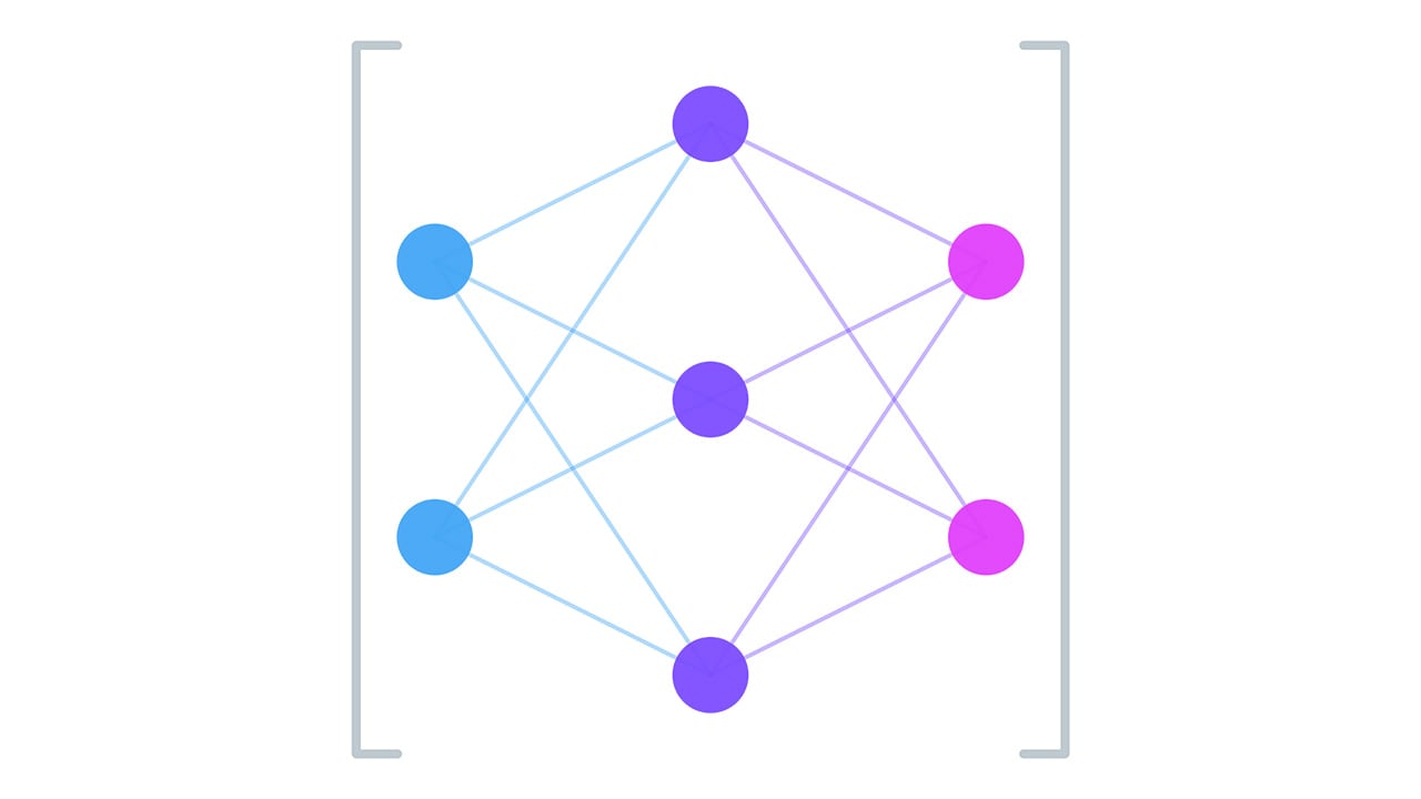
The Koch snowflake work graph thus consists of four nodes in total: two compute nodes and two mesh nodes. You can follow the links to the full source code on GitHub.
EntryNode: This node is invoked from the CPU and initializes the Koch snowflake with a single triangle as can be seen on the right.
This triangle consists of a single output to the TriangleMeshNode and three outputs to the SnowflakeNode, one for each edge of the triangle.SnowflakeNode: Recursively processes line segments by dividing them into four new line segments. The area of the Koch snowflake enclosed by these new line segments is filled using the TriangleMeshNode. If the recursion limit is reached, the line segment is drawn on screen using the LineMeshNode. The different outputs of the SnowflakeNode are shown in the table below.
| Snowflake Input | Snowflake Recursive Output | Snowflake Tail Output |
|---|---|---|
 |  |  |
LineMeshNode: receives a start and end position in the input record and draws a line between them.
As lines in the Koch fractal don’t meet a right angles, the mesh shader draws the caps of the line as equilateral triangles. In total this mesh node exports six vertices and four triangles.TriangleMeshNode: receives three vertex positions in the input record and draws a single triangle with them.The full graph structure can be seen in the figure below. Though not shown here, the two graphics pipelines for the two mesh nodes use the same pixel shader, which fills the rendered triangles with a color, which is set in the mesh shader and passed through per-primitive attributes.

As mesh nodes do not guarantee any draw order, we use a depth buffer to always draw the outer fractal lines in front of the inner triangles.