Setup
Adding the Robot
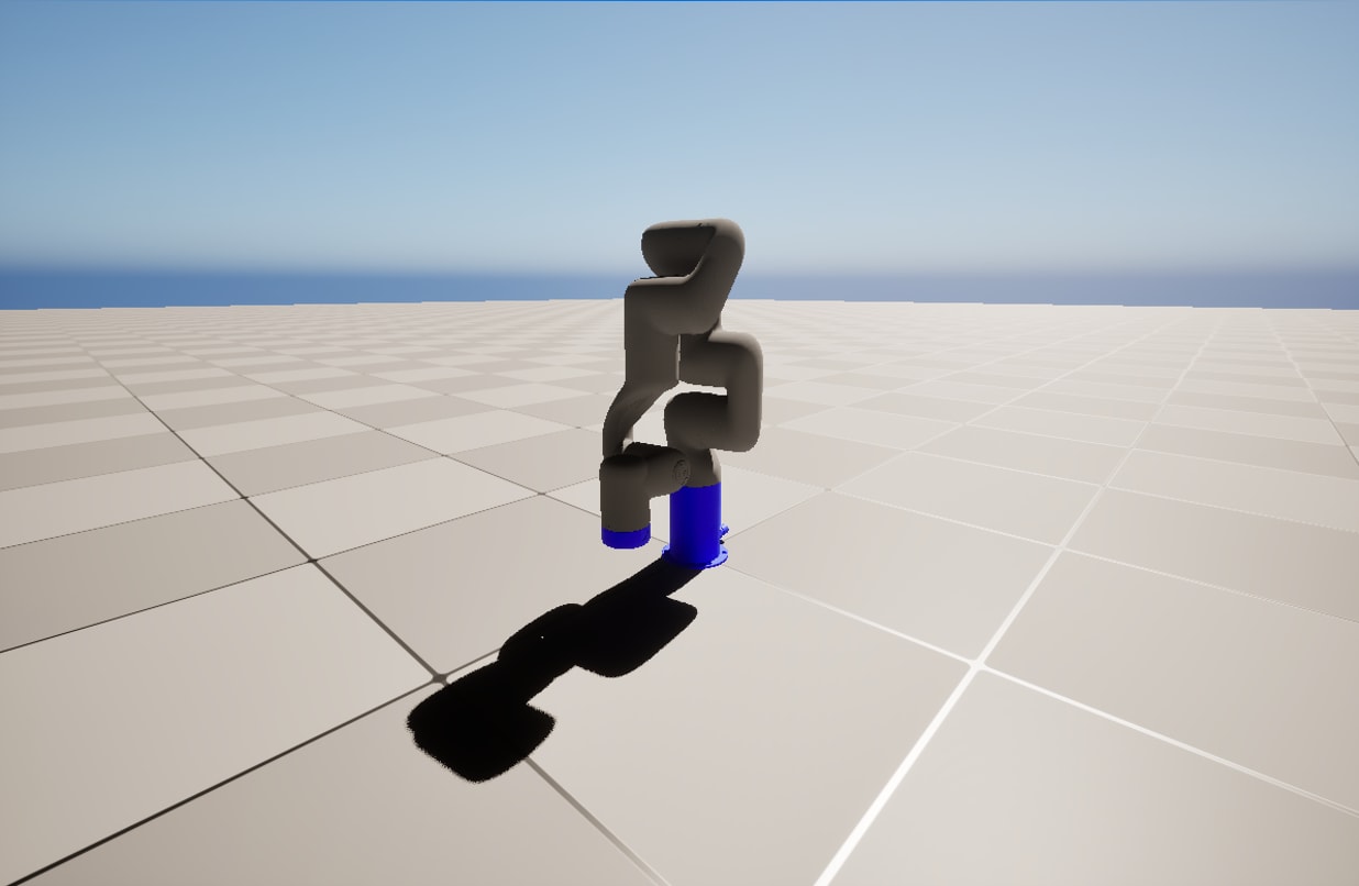
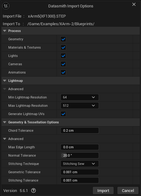
The 3D file of the X-Arm 5 provided by the manufacturer is a .STEP CAD file. To port this model into Unreal Engine, use the Datasmith CAD Importer plugin. Select the Quickly add to the project menu, and then File Import under Datasmith. Use the default options.
It will be added to your open map, or a new one if none was open.
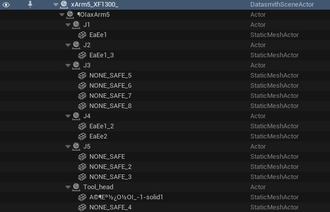
Select all actors under xArm5_XF1300_
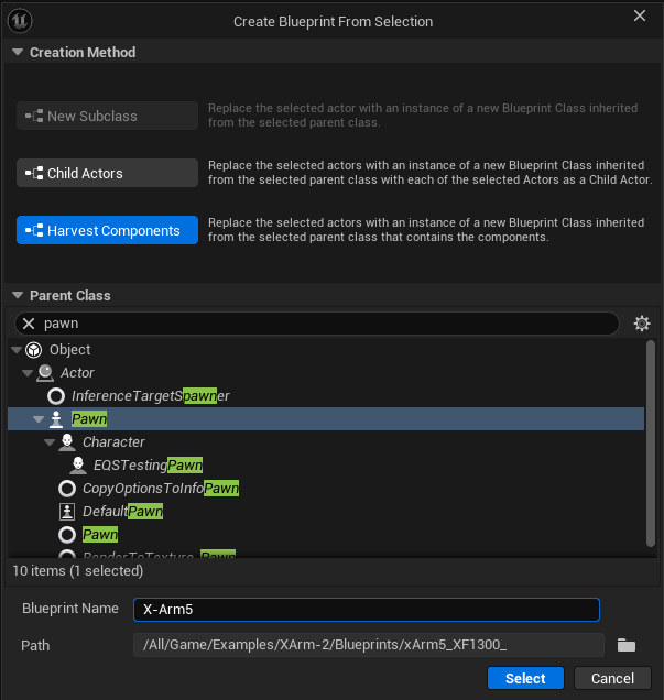
Convert selection to a Blueprint class
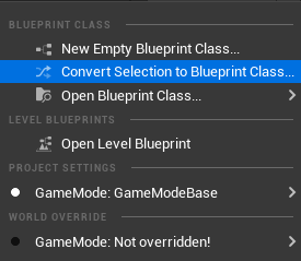
Select Harvest Components, and make the parent class a Pawn. Name it “X-Arm5”
Assembly
Open the newly created Pawn Blueprint for the XArm.
We are going to rename the static mesh components to make the imported names more clear. The imported meshes in the content drawer should be identical:
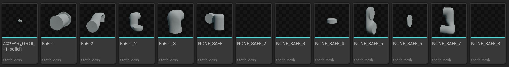
Follow the table below to rename each of the components we are going to use. Delete any static meshes not included here.
Component Naming Table
| Static Mesh Component New Name | Old Name |
|---|---|
| J1 | EaEe1 |
| J2 | EaEe1_3 |
| J3a | NONE_SAFE_5 |
| J3b | NONE_SAFE_7 |
| J4a | EaEe1_2 |
| J4b | EaEe2 |
| J5 | NONE_SAFE |
| J6 | NONE_SAFE_4 |
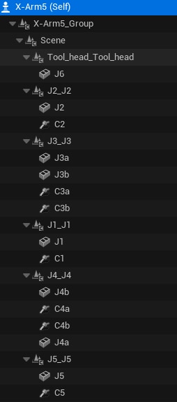
For each scene group (J1_J1, J2_J2, …, Tool_head_Tool_head) that contain the meshes, add corresponding Physics Constraint components named C1, C2, etc., except for C6.
Your component menu should look similar to the following now. Order does not matter.
Configuration
Now, we need to setup the meshes & constraints to have the proper physics setup for the robot to behave correctly.
Meshes
The meshes do not have a collision mesh by default when imported via Datasmith, so we need to configure these manually in order to use phyiscs on the robot. To do this, go to the location in the Content Drawer where the meshes were imported, and follow this table to configure the collisions.
You only need to change the collision on the static meshes we are using, reference these from the assembly-components section.
| Static Mesh | Collision Type | Simple Collision Physical Material | Collision Presets |
|---|---|---|---|
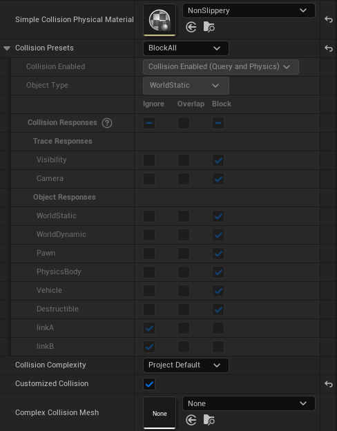
| EaEe1 | 26DOP Simplified | NonSlippery | BlockAll |
| All other 7 | 26DOP Simplified | None | PhysicsActor |
Your collsions should look like this for EaEe1:
and like this for the others:
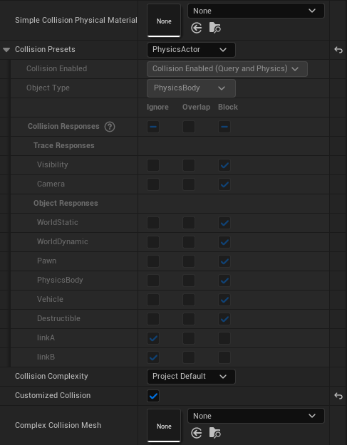
Note: If you don’t see NonSlippery as an option, this is a part of the starter content - an option that can be selected when creating the uproject
Head back to the X-Arm5 Blueprint, and setup the following options on each static mesh component:
-
For J1, set the following under Constraints
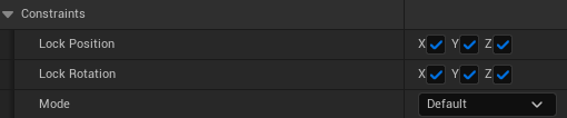
-
For J6, set the following under Constraints
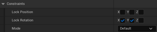
-
Set Linear & Angular damping to 5.0 for J1-6
-
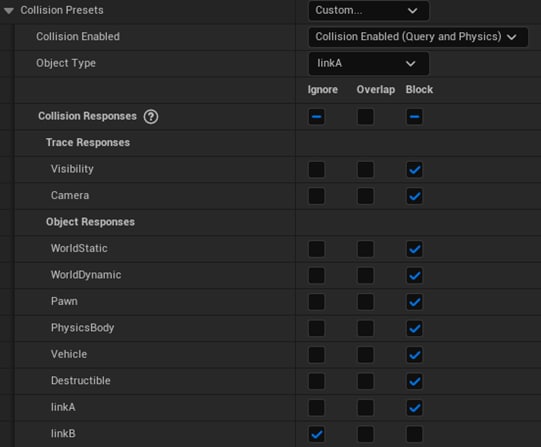
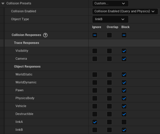
We need to ensure the parts do not interfere with each other. To do so, we need to alternate the object type in the collision presets. Follow the table to configure this.
-
Each mesh should have the Collision Presets set to Custom… and the Collision Enabled set to Collision Enabled (Query and Physics)
-
On meshes that are of type linkA, set linkA to Block and linkB to Ignore under Collision Responses
-
Conversely, meshes of type linkB should have linkA set to Ignore and linkB to Block
-
| Static Mesh Component | Object Type |
|---|---|
| J1 | linkA |
| J2 | linkB |
| J3a | linkA |
| J3b | linkB |
| J4a | linkA |
| J4b | linkB |
| J5 | linkA |
| J6 | linkB |
The mesh collision presets menus should look like the following now:
- Turn on Simulate Physics for J2-6. Leave it off for J1
- Turn off Enable Gravity for J1-6
Constraints
Each piece of the arm needs to be connected to the next corresponding piece, as well as having its motion restricted to only the directions allowed by the physical robot.
-
For each C1-C5, set Component Name 1 to the corresponding mesh, and Component Name 2 to the next mesh (i.e. for C1, Component Name 1 is J1, and Component Name 2 is J2, etc.)
- Be sure that C3a connects J3a and J3b, and likewise for C4a
-
Set the Linear Limits to Locked in each axis, for each physics constraint component
-
Set the Angular Limits as described in the table:
| Physics Constraint | Swing 1 Motion | Swing 2 Motion | Twist Motion |
|---|---|---|---|
| C1 | Free | Locked | Locked |
| C2, C3b, C4b | Locked | Free | Locked |
| C3a, C4a, C5 | Locked | Locked | Locked |
- Set the Angular Drive Mode according to the table:
| Physics Constraint | Angular Drive Mode |
|---|---|
| C1, C2, C3b, C4b | Twist and Swing |
| C3a, C4a, C5 | SLERP |
Functionality
Variables
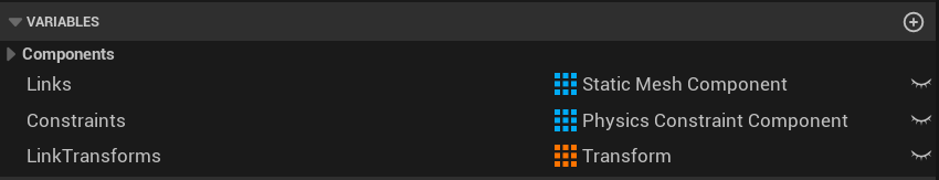
Add the following variables:
-
Links (Static Mesh Component Array)
-
Constraints (Physics Constraint Component Array)
-
LinkTransforms (Transform Array)
It should look like this now
Functions
-
Set the function EventGraph as follows
Begin Object Class=/Script/BlueprintGraph.K2Node_Event Name="K2Node_Event_0" ExportPath="/Script/BlueprintGraph.K2Node_Event'/Game/Examples/XArm-2/Blueprints/X-Arm5.X-Arm5:EventGraph.K2Node_Event_0'" EventReference=(MemberParent="/Script/CoreUObject.Class'/Script/Engine.Actor'",MemberName="ReceiveBeginPlay") bOverrideFunction=True bCommentBubblePinned=True NodeGuid=BFDE664D43B7726897CD5EBE6FAF5F5B CustomProperties Pin (PinId=3E0ED82D473D3F42F6DDD3AD5E371E28,PinName="OutputDelegate",Direction="EGPD_Output",PinType.PinCategory="delegate",PinType.PinSubCategory="",PinType.PinSubCategoryObject=None,PinType.PinSubCategoryMemberReference=(MemberParent="/Script/CoreUObject.Class'/Script/Engine.Actor'",MemberName="ReceiveBeginPlay"),PinType.PinValueType=(),PinType.ContainerType=None,PinType.bIsReference=False,PinType.bIsConst=False,PinType.bIsWeakPointer=False,PinType.bIsUObjectWrapper=False,PinType.bSerializeAsSinglePrecisionFloat=False,PersistentGuid=00000000000000000000000000000000,bHidden=False,bNotConnectable=False,bDefaultValueIsReadOnly=False,bDefaultValueIsIgnored=False,bAdvancedView=False,bOrphanedPin=False,) CustomProperties Pin (PinId=0B86E6CA4585325D5EC8888D49929F4A,PinName="then",Direction="EGPD_Output",PinType.PinCategory="exec",PinType.PinSubCategory="",PinType.PinSubCategoryObject=None,PinType.PinSubCategoryMemberReference=(),PinType.PinValueType=(),PinType.ContainerType=None,PinType.bIsReference=False,PinType.bIsConst=False,PinType.bIsWeakPointer=False,PinType.bIsUObjectWrapper=False,PinType.bSerializeAsSinglePrecisionFloat=False,LinkedTo=(K2Node_VariableSet_0 CD56BB854AA9136B034F6984AD220CDE,),PersistentGuid=00000000000000000000000000000000,bHidden=False,bNotConnectable=False,bDefaultValueIsReadOnly=False,bDefaultValueIsIgnored=False,bAdvancedView=False,bOrphanedPin=False,) End Object Begin Object Class=/Script/BlueprintGraph.K2Node_Event Name="K2Node_Event_1" ExportPath="/Script/BlueprintGraph.K2Node_Event'/Game/Examples/XArm-2/Blueprints/X-Arm5.X-Arm5:EventGraph.K2Node_Event_1'" EventReference=(MemberParent="/Script/CoreUObject.Class'/Script/Engine.Actor'",MemberName="ReceiveActorBeginOverlap") bOverrideFunction=True NodePosX=-80 NodePosY=1120 EnabledState=Disabled bCommentBubblePinned=True bCommentBubbleVisible=True NodeComment="This node is disabled and will not be called.\r\nDrag off pins to build functionality." NodeGuid=27A5551A49F1580664D2E19887A2FF52 CustomProperties Pin (PinId=BD2593AC4F24351520ABDD86463D0EBF,PinName="OutputDelegate",Direction="EGPD_Output",PinType.PinCategory="delegate",PinType.PinSubCategory="",PinType.PinSubCategoryObject=None,PinType.PinSubCategoryMemberReference=(MemberParent="/Script/CoreUObject.Class'/Script/Engine.Actor'",MemberName="ReceiveActorBeginOverlap"),PinType.PinValueType=(),PinType.ContainerType=None,PinType.bIsReference=False,PinType.bIsConst=False,PinType.bIsWeakPointer=False,PinType.bIsUObjectWrapper=False,PinType.bSerializeAsSinglePrecisionFloat=False,PersistentGuid=00000000000000000000000000000000,bHidden=False,bNotConnectable=False,bDefaultValueIsReadOnly=False,bDefaultValueIsIgnored=False,bAdvancedView=False,bOrphanedPin=False,) CustomProperties Pin (PinId=4030900A4DD2DA22B43625821A2ECF5E,PinName="then",Direction="EGPD_Output",PinType.PinCategory="exec",PinType.PinSubCategory="",PinType.PinSubCategoryObject=None,PinType.PinSubCategoryMemberReference=(),PinType.PinValueType=(),PinType.ContainerType=None,PinType.bIsReference=False,PinType.bIsConst=False,PinType.bIsWeakPointer=False,PinType.bIsUObjectWrapper=False,PinType.bSerializeAsSinglePrecisionFloat=False,PersistentGuid=00000000000000000000000000000000,bHidden=False,bNotConnectable=False,bDefaultValueIsReadOnly=False,bDefaultValueIsIgnored=False,bAdvancedView=False,bOrphanedPin=False,) CustomProperties Pin (PinId=030CDA064208458044A9FA9DE4A0EB56,PinName="OtherActor",PinToolTip="Other Actor\nActor Object Reference",Direction="EGPD_Output",PinType.PinCategory="object",PinType.PinSubCategory="",PinType.PinSubCategoryObject="/Script/CoreUObject.Class'/Script/Engine.Actor'",PinType.PinSubCategoryMemberReference=(),PinType.PinValueType=(),PinType.ContainerType=None,PinType.bIsReference=False,PinType.bIsConst=False,PinType.bIsWeakPointer=False,PinType.bIsUObjectWrapper=False,PinType.bSerializeAsSinglePrecisionFloat=False,PersistentGuid=00000000000000000000000000000000,bHidden=False,bNotConnectable=False,bDefaultValueIsReadOnly=False,bDefaultValueIsIgnored=False,bAdvancedView=False,bOrphanedPin=False,) End Object Begin Object Class=/Script/BlueprintGraph.K2Node_Event Name="K2Node_Event_2" ExportPath="/Script/BlueprintGraph.K2Node_Event'/Game/Examples/XArm-2/Blueprints/X-Arm5.X-Arm5:EventGraph.K2Node_Event_2'" EventReference=(MemberParent="/Script/CoreUObject.Class'/Script/Engine.Actor'",MemberName="ReceiveTick") bOverrideFunction=True NodePosX=-80 NodePosY=1328 EnabledState=Disabled bCommentBubblePinned=True bCommentBubbleVisible=True NodeComment="This node is disabled and will not be called.\nDrag off pins to build functionality." NodeGuid=2D0E4E7C4E7A7A807D9886BFD60C44EB CustomProperties Pin (PinId=EEB011B74F7F89D77F275F94096E80AA,PinName="OutputDelegate",Direction="EGPD_Output",PinType.PinCategory="delegate",PinType.PinSubCategory="",PinType.PinSubCategoryObject=None,PinType.PinSubCategoryMemberReference=(MemberParent="/Script/CoreUObject.Class'/Script/Engine.Actor'",MemberName="ReceiveTick"),PinType.PinValueType=(),PinType.ContainerType=None,PinType.bIsReference=False,PinType.bIsConst=False,PinType.bIsWeakPointer=False,PinType.bIsUObjectWrapper=False,PinType.bSerializeAsSinglePrecisionFloat=False,PersistentGuid=00000000000000000000000000000000,bHidden=False,bNotConnectable=False,bDefaultValueIsReadOnly=False,bDefaultValueIsIgnored=False,bAdvancedView=False,bOrphanedPin=False,) CustomProperties Pin (PinId=A00459F241B20D64687D90AA16B74183,PinName="then",Direction="EGPD_Output",PinType.PinCategory="exec",PinType.PinSubCategory="",PinType.PinSubCategoryObject=None,PinType.PinSubCategoryMemberReference=(),PinType.PinValueType=(),PinType.ContainerType=None,PinType.bIsReference=False,PinType.bIsConst=False,PinType.bIsWeakPointer=False,PinType.bIsUObjectWrapper=False,PinType.bSerializeAsSinglePrecisionFloat=False,PersistentGuid=00000000000000000000000000000000,bHidden=False,bNotConnectable=False,bDefaultValueIsReadOnly=False,bDefaultValueIsIgnored=False,bAdvancedView=False,bOrphanedPin=False,) CustomProperties Pin (PinId=BEA30D824A307B822DC7E699AFE9C66A,PinName="DeltaSeconds",PinToolTip="Delta Seconds\nFloat (single-precision)",Direction="EGPD_Output",PinType.PinCategory="real",PinType.PinSubCategory="float",PinType.PinSubCategoryObject=None,PinType.PinSubCategoryMemberReference=(),PinType.PinValueType=(),PinType.ContainerType=None,PinType.bIsReference=False,PinType.bIsConst=False,PinType.bIsWeakPointer=False,PinType.bIsUObjectWrapper=False,PinType.bSerializeAsSinglePrecisionFloat=False,DefaultValue="0.0",AutogeneratedDefaultValue="0.0",PersistentGuid=00000000000000000000000000000000,bHidden=False,bNotConnectable=False,bDefaultValueIsReadOnly=False,bDefaultValueIsIgnored=False,bAdvancedView=False,bOrphanedPin=False,) End Object Begin Object Class=/Script/BlueprintGraph.K2Node_VariableSet Name="K2Node_VariableSet_0" ExportPath="/Script/BlueprintGraph.K2Node_VariableSet'/Game/Examples/XArm-2/Blueprints/X-Arm5.X-Arm5:EventGraph.K2Node_VariableSet_0'" VariableReference=(MemberName="Constraints",MemberGuid=3138ECC247502CA95A4D8AAEDF0EFB89,bSelfContext=True) NodePosX=784 NodePosY=16 NodeGuid=A033667143B38C5707D70BA0FBFE2C2D CustomProperties Pin (PinId=CD56BB854AA9136B034F6984AD220CDE,PinName="execute",PinType.PinCategory="exec",PinType.PinSubCategory="",PinType.PinSubCategoryObject=None,PinType.PinSubCategoryMemberReference=(),PinType.PinValueType=(),PinType.ContainerType=None,PinType.bIsReference=False,PinType.bIsConst=False,PinType.bIsWeakPointer=False,PinType.bIsUObjectWrapper=False,PinType.bSerializeAsSinglePrecisionFloat=False,LinkedTo=(K2Node_Event_0 0B86E6CA4585325D5EC8888D49929F4A,),PersistentGuid=00000000000000000000000000000000,bHidden=False,bNotConnectable=False,bDefaultValueIsReadOnly=False,bDefaultValueIsIgnored=False,bAdvancedView=False,bOrphanedPin=False,) CustomProperties Pin (PinId=A93D8DE64E39A41BD26DF688FDC9A072,PinName="then",Direction="EGPD_Output",PinType.PinCategory="exec",PinType.PinSubCategory="",PinType.PinSubCategoryObject=None,PinType.PinSubCategoryMemberReference=(),PinType.PinValueType=(),PinType.ContainerType=None,PinType.bIsReference=False,PinType.bIsConst=False,PinType.bIsWeakPointer=False,PinType.bIsUObjectWrapper=False,PinType.bSerializeAsSinglePrecisionFloat=False,LinkedTo=(K2Node_VariableSet_1 1E73260A43885CB708A4F5B8FF96AC28,),PersistentGuid=00000000000000000000000000000000,bHidden=False,bNotConnectable=False,bDefaultValueIsReadOnly=False,bDefaultValueIsIgnored=False,bAdvancedView=False,bOrphanedPin=False,) CustomProperties Pin (PinId=C3B64E1749E0F08A6448A0AA05B837FE,PinName="Constraints",PinType.PinCategory="object",PinType.PinSubCategory="",PinType.PinSubCategoryObject="/Script/CoreUObject.Class'/Script/Engine.PhysicsConstraintComponent'",PinType.PinSubCategoryMemberReference=(),PinType.PinValueType=(),PinType.ContainerType=Array,PinType.bIsReference=False,PinType.bIsConst=False,PinType.bIsWeakPointer=False,PinType.bIsUObjectWrapper=False,PinType.bSerializeAsSinglePrecisionFloat=False,LinkedTo=(K2Node_MakeArray_0 4BAEC50A4A405F17C3EA1586F946211B,),PersistentGuid=00000000000000000000000000000000,bHidden=False,bNotConnectable=False,bDefaultValueIsReadOnly=False,bDefaultValueIsIgnored=False,bAdvancedView=False,bOrphanedPin=False,) CustomProperties Pin (PinId=C45250F741437AF84B74359B85B448F7,PinName="Output_Get",PinToolTip="Retrieves the value of the variable, can use instead of a separate Get node",Direction="EGPD_Output",PinType.PinCategory="object",PinType.PinSubCategory="",PinType.PinSubCategoryObject="/Script/CoreUObject.Class'/Script/Engine.PhysicsConstraintComponent'",PinType.PinSubCategoryMemberReference=(),PinType.PinValueType=(),PinType.ContainerType=Array,PinType.bIsReference=False,PinType.bIsConst=False,PinType.bIsWeakPointer=False,PinType.bIsUObjectWrapper=False,PinType.bSerializeAsSinglePrecisionFloat=False,PersistentGuid=00000000000000000000000000000000,bHidden=False,bNotConnectable=False,bDefaultValueIsReadOnly=False,bDefaultValueIsIgnored=False,bAdvancedView=False,bOrphanedPin=False,) CustomProperties Pin (PinId=45A039EE43A246F1C27D938AC1BF24CB,PinName="self",PinFriendlyName=NSLOCTEXT("K2Node", "Target", "Target"),PinType.PinCategory="object",PinType.PinSubCategory="",PinType.PinSubCategoryObject="/Script/Engine.BlueprintGeneratedClass'/Game/Examples/XArm-2/Blueprints/X-Arm5.X-Arm5_C'",PinType.PinSubCategoryMemberReference=(),PinType.PinValueType=(),PinType.ContainerType=None,PinType.bIsReference=False,PinType.bIsConst=False,PinType.bIsWeakPointer=False,PinType.bIsUObjectWrapper=False,PinType.bSerializeAsSinglePrecisionFloat=False,PersistentGuid=00000000000000000000000000000000,bHidden=True,bNotConnectable=False,bDefaultValueIsReadOnly=False,bDefaultValueIsIgnored=False,bAdvancedView=False,bOrphanedPin=False,) End Object Begin Object Class=/Script/BlueprintGraph.K2Node_MakeArray Name="K2Node_MakeArray_0" ExportPath="/Script/BlueprintGraph.K2Node_MakeArray'/Game/Examples/XArm-2/Blueprints/X-Arm5.X-Arm5:EventGraph.K2Node_MakeArray_0'" NumInputs=7 NodePosX=544 NodePosY=-240 NodeGuid=0DE1AD2949B73A5DCC93898AAD64E568 CustomProperties Pin (PinId=4BAEC50A4A405F17C3EA1586F946211B,PinName="Array",Direction="EGPD_Output",PinType.PinCategory="object",PinType.PinSubCategory="",PinType.PinSubCategoryObject="/Script/CoreUObject.Class'/Script/Engine.PhysicsConstraintComponent'",PinType.PinSubCategoryMemberReference=(),PinType.PinValueType=(),PinType.ContainerType=Array,PinType.bIsReference=False,PinType.bIsConst=False,PinType.bIsWeakPointer=False,PinType.bIsUObjectWrapper=False,PinType.bSerializeAsSinglePrecisionFloat=False,LinkedTo=(K2Node_VariableSet_0 C3B64E1749E0F08A6448A0AA05B837FE,),PersistentGuid=00000000000000000000000000000000,bHidden=False,bNotConnectable=False,bDefaultValueIsReadOnly=False,bDefaultValueIsIgnored=False,bAdvancedView=False,bOrphanedPin=False,) CustomProperties Pin (PinId=05E5563B4403787B52201D963FABB7A5,PinName="[0]",PinType.PinCategory="object",PinType.PinSubCategory="",PinType.PinSubCategoryObject="/Script/CoreUObject.Class'/Script/Engine.PhysicsConstraintComponent'",PinType.PinSubCategoryMemberReference=(),PinType.PinValueType=(),PinType.ContainerType=None,PinType.bIsReference=False,PinType.bIsConst=False,PinType.bIsWeakPointer=False,PinType.bIsUObjectWrapper=False,PinType.bSerializeAsSinglePrecisionFloat=False,LinkedTo=(K2Node_VariableGet_0 D5FAD7514742A9A9F57088870D18E3C0,),PersistentGuid=00000000000000000000000000000000,bHidden=False,bNotConnectable=False,bDefaultValueIsReadOnly=False,bDefaultValueIsIgnored=False,bAdvancedView=False,bOrphanedPin=False,) CustomProperties Pin (PinId=0AA3E49A4428F20A3AEA32BA4A3AC47F,PinName="[1]",PinType.PinCategory="object",PinType.PinSubCategory="",PinType.PinSubCategoryObject="/Script/CoreUObject.Class'/Script/Engine.PhysicsConstraintComponent'",PinType.PinSubCategoryMemberReference=(),PinType.PinValueType=(),PinType.ContainerType=None,PinType.bIsReference=False,PinType.bIsConst=False,PinType.bIsWeakPointer=False,PinType.bIsUObjectWrapper=False,PinType.bSerializeAsSinglePrecisionFloat=False,LinkedTo=(K2Node_VariableGet_1 1118A6664584921DB6D9ED8B603641DC,),PersistentGuid=00000000000000000000000000000000,bHidden=False,bNotConnectable=False,bDefaultValueIsReadOnly=False,bDefaultValueIsIgnored=False,bAdvancedView=False,bOrphanedPin=False,) CustomProperties Pin (PinId=030741834BF95AD96EF141A4C736FC68,PinName="[2]",PinType.PinCategory="object",PinType.PinSubCategory="",PinType.PinSubCategoryObject="/Script/CoreUObject.Class'/Script/Engine.PhysicsConstraintComponent'",PinType.PinSubCategoryMemberReference=(),PinType.PinValueType=(),PinType.ContainerType=None,PinType.bIsReference=False,PinType.bIsConst=False,PinType.bIsWeakPointer=False,PinType.bIsUObjectWrapper=False,PinType.bSerializeAsSinglePrecisionFloat=False,LinkedTo=(K2Node_VariableGet_2 4E50058E4C65BA63B604F6A1A7C094F3,),PersistentGuid=00000000000000000000000000000000,bHidden=False,bNotConnectable=False,bDefaultValueIsReadOnly=False,bDefaultValueIsIgnored=False,bAdvancedView=False,bOrphanedPin=False,) CustomProperties Pin (PinId=49B65BF54ACB4B620A7FA5A042B63259,PinName="[3]",PinType.PinCategory="object",PinType.PinSubCategory="",PinType.PinSubCategoryObject="/Script/CoreUObject.Class'/Script/Engine.PhysicsConstraintComponent'",PinType.PinSubCategoryMemberReference=(),PinType.PinValueType=(),PinType.ContainerType=None,PinType.bIsReference=False,PinType.bIsConst=False,PinType.bIsWeakPointer=False,PinType.bIsUObjectWrapper=False,PinType.bSerializeAsSinglePrecisionFloat=False,LinkedTo=(K2Node_VariableGet_3 4608FC9C4DDCBEF7048F37BBBAC09B53,),PersistentGuid=00000000000000000000000000000000,bHidden=False,bNotConnectable=False,bDefaultValueIsReadOnly=False,bDefaultValueIsIgnored=False,bAdvancedView=False,bOrphanedPin=False,) CustomProperties Pin (PinId=E20453684443C98B5340CC8F03363695,PinName="[4]",PinType.PinCategory="object",PinType.PinSubCategory="",PinType.PinSubCategoryObject="/Script/CoreUObject.Class'/Script/Engine.PhysicsConstraintComponent'",PinType.PinSubCategoryMemberReference=(),PinType.PinValueType=(),PinType.ContainerType=None,PinType.bIsReference=False,PinType.bIsConst=False,PinType.bIsWeakPointer=False,PinType.bIsUObjectWrapper=False,PinType.bSerializeAsSinglePrecisionFloat=False,LinkedTo=(K2Node_VariableGet_4 9ED4015B4AEDF29DDC0B86A98B0BFCCD,),PersistentGuid=00000000000000000000000000000000,bHidden=False,bNotConnectable=False,bDefaultValueIsReadOnly=False,bDefaultValueIsIgnored=False,bAdvancedView=False,bOrphanedPin=False,) CustomProperties Pin (PinId=696A41354665566717BC6F8719CCF2DB,PinName="[5]",PinType.PinCategory="object",PinType.PinSubCategory="",PinType.PinSubCategoryObject="/Script/CoreUObject.Class'/Script/Engine.PhysicsConstraintComponent'",PinType.PinSubCategoryMemberReference=(),PinType.PinValueType=(),PinType.ContainerType=None,PinType.bIsReference=False,PinType.bIsConst=False,PinType.bIsWeakPointer=False,PinType.bIsUObjectWrapper=False,PinType.bSerializeAsSinglePrecisionFloat=False,LinkedTo=(K2Node_VariableGet_5 312A48C746783CE7873E72AE6451C269,),PersistentGuid=00000000000000000000000000000000,bHidden=False,bNotConnectable=False,bDefaultValueIsReadOnly=False,bDefaultValueIsIgnored=False,bAdvancedView=False,bOrphanedPin=False,) CustomProperties Pin (PinId=8C10E633422ECD392C659DB3347B080E,PinName="[6]",PinType.PinCategory="object",PinType.PinSubCategory="",PinType.PinSubCategoryObject="/Script/CoreUObject.Class'/Script/Engine.PhysicsConstraintComponent'",PinType.PinSubCategoryMemberReference=(),PinType.PinValueType=(),PinType.ContainerType=None,PinType.bIsReference=False,PinType.bIsConst=False,PinType.bIsWeakPointer=False,PinType.bIsUObjectWrapper=False,PinType.bSerializeAsSinglePrecisionFloat=False,LinkedTo=(K2Node_VariableGet_6 CD85903649F0622D3AD8429139A0E832,),PersistentGuid=00000000000000000000000000000000,bHidden=False,bNotConnectable=False,bDefaultValueIsReadOnly=False,bDefaultValueIsIgnored=False,bAdvancedView=False,bOrphanedPin=False,) End Object Begin Object Class=/Script/BlueprintGraph.K2Node_VariableGet Name="K2Node_VariableGet_0" ExportPath="/Script/BlueprintGraph.K2Node_VariableGet'/Game/Examples/XArm-2/Blueprints/X-Arm5.X-Arm5:EventGraph.K2Node_VariableGet_0'" VariableReference=(MemberName="C1",bSelfContext=True) NodePosX=336 NodePosY=-217 NodeGuid=C7CD54234F4ED28FFB2F9EA6E94D892F CustomProperties Pin (PinId=D5FAD7514742A9A9F57088870D18E3C0,PinName="C1",Direction="EGPD_Output",PinType.PinCategory="object",PinType.PinSubCategory="",PinType.PinSubCategoryObject="/Script/CoreUObject.Class'/Script/Engine.PhysicsConstraintComponent'",PinType.PinSubCategoryMemberReference=(),PinType.PinValueType=(),PinType.ContainerType=None,PinType.bIsReference=False,PinType.bIsConst=False,PinType.bIsWeakPointer=False,PinType.bIsUObjectWrapper=False,PinType.bSerializeAsSinglePrecisionFloat=False,LinkedTo=(K2Node_MakeArray_0 05E5563B4403787B52201D963FABB7A5,),PersistentGuid=00000000000000000000000000000000,bHidden=False,bNotConnectable=False,bDefaultValueIsReadOnly=False,bDefaultValueIsIgnored=False,bAdvancedView=False,bOrphanedPin=False,) CustomProperties Pin (PinId=2525AC734FFADB79C1A1228494A7B819,PinName="self",PinFriendlyName=NSLOCTEXT("K2Node", "Target", "Target"),PinType.PinCategory="object",PinType.PinSubCategory="",PinType.PinSubCategoryObject="/Script/Engine.BlueprintGeneratedClass'/Game/Examples/XArm-2/Blueprints/X-Arm5.X-Arm5_C'",PinType.PinSubCategoryMemberReference=(),PinType.PinValueType=(),PinType.ContainerType=None,PinType.bIsReference=False,PinType.bIsConst=False,PinType.bIsWeakPointer=False,PinType.bIsUObjectWrapper=False,PinType.bSerializeAsSinglePrecisionFloat=False,PersistentGuid=00000000000000000000000000000000,bHidden=True,bNotConnectable=False,bDefaultValueIsReadOnly=False,bDefaultValueIsIgnored=False,bAdvancedView=False,bOrphanedPin=False,) End Object Begin Object Class=/Script/BlueprintGraph.K2Node_VariableGet Name="K2Node_VariableGet_1" ExportPath="/Script/BlueprintGraph.K2Node_VariableGet'/Game/Examples/XArm-2/Blueprints/X-Arm5.X-Arm5:EventGraph.K2Node_VariableGet_1'" VariableReference=(MemberName="C2",bSelfContext=True) NodePosX=192 NodePosY=-187 NodeGuid=D87F4FE34264F3F39DE66FBB36E98EFA CustomProperties Pin (PinId=1118A6664584921DB6D9ED8B603641DC,PinName="C2",Direction="EGPD_Output",PinType.PinCategory="object",PinType.PinSubCategory="",PinType.PinSubCategoryObject="/Script/CoreUObject.Class'/Script/Engine.PhysicsConstraintComponent'",PinType.PinSubCategoryMemberReference=(),PinType.PinValueType=(),PinType.ContainerType=None,PinType.bIsReference=False,PinType.bIsConst=False,PinType.bIsWeakPointer=False,PinType.bIsUObjectWrapper=False,PinType.bSerializeAsSinglePrecisionFloat=False,LinkedTo=(K2Node_MakeArray_0 0AA3E49A4428F20A3AEA32BA4A3AC47F,),PersistentGuid=00000000000000000000000000000000,bHidden=False,bNotConnectable=False,bDefaultValueIsReadOnly=False,bDefaultValueIsIgnored=False,bAdvancedView=False,bOrphanedPin=False,) CustomProperties Pin (PinId=EAF41D6143640F523A1A1BA5D59E7369,PinName="self",PinFriendlyName=NSLOCTEXT("K2Node", "Target", "Target"),PinType.PinCategory="object",PinType.PinSubCategory="",PinType.PinSubCategoryObject="/Script/Engine.BlueprintGeneratedClass'/Game/Examples/XArm-2/Blueprints/X-Arm5.X-Arm5_C'",PinType.PinSubCategoryMemberReference=(),PinType.PinValueType=(),PinType.ContainerType=None,PinType.bIsReference=False,PinType.bIsConst=False,PinType.bIsWeakPointer=False,PinType.bIsUObjectWrapper=False,PinType.bSerializeAsSinglePrecisionFloat=False,PersistentGuid=00000000000000000000000000000000,bHidden=True,bNotConnectable=False,bDefaultValueIsReadOnly=False,bDefaultValueIsIgnored=False,bAdvancedView=False,bOrphanedPin=False,) End Object Begin Object Class=/Script/BlueprintGraph.K2Node_VariableGet Name="K2Node_VariableGet_2" ExportPath="/Script/BlueprintGraph.K2Node_VariableGet'/Game/Examples/XArm-2/Blueprints/X-Arm5.X-Arm5:EventGraph.K2Node_VariableGet_2'" VariableReference=(MemberName="C3a",bSelfContext=True) NodePosX=336 NodePosY=-157 NodeGuid=9BD5C41A4EA12F96B94AC4B8C5F7FDC3 CustomProperties Pin (PinId=4E50058E4C65BA63B604F6A1A7C094F3,PinName="C3a",Direction="EGPD_Output",PinType.PinCategory="object",PinType.PinSubCategory="",PinType.PinSubCategoryObject="/Script/CoreUObject.Class'/Script/Engine.PhysicsConstraintComponent'",PinType.PinSubCategoryMemberReference=(),PinType.PinValueType=(),PinType.ContainerType=None,PinType.bIsReference=False,PinType.bIsConst=False,PinType.bIsWeakPointer=False,PinType.bIsUObjectWrapper=False,PinType.bSerializeAsSinglePrecisionFloat=False,LinkedTo=(K2Node_MakeArray_0 030741834BF95AD96EF141A4C736FC68,),PersistentGuid=00000000000000000000000000000000,bHidden=False,bNotConnectable=False,bDefaultValueIsReadOnly=False,bDefaultValueIsIgnored=False,bAdvancedView=False,bOrphanedPin=False,) CustomProperties Pin (PinId=0557F2864F044343F570F1AE08F03F87,PinName="self",PinFriendlyName=NSLOCTEXT("K2Node", "Target", "Target"),PinType.PinCategory="object",PinType.PinSubCategory="",PinType.PinSubCategoryObject="/Script/Engine.BlueprintGeneratedClass'/Game/Examples/XArm-2/Blueprints/X-Arm5.X-Arm5_C'",PinType.PinSubCategoryMemberReference=(),PinType.PinValueType=(),PinType.ContainerType=None,PinType.bIsReference=False,PinType.bIsConst=False,PinType.bIsWeakPointer=False,PinType.bIsUObjectWrapper=False,PinType.bSerializeAsSinglePrecisionFloat=False,PersistentGuid=00000000000000000000000000000000,bHidden=True,bNotConnectable=False,bDefaultValueIsReadOnly=False,bDefaultValueIsIgnored=False,bAdvancedView=False,bOrphanedPin=False,) End Object Begin Object Class=/Script/BlueprintGraph.K2Node_VariableGet Name="K2Node_VariableGet_3" ExportPath="/Script/BlueprintGraph.K2Node_VariableGet'/Game/Examples/XArm-2/Blueprints/X-Arm5.X-Arm5:EventGraph.K2Node_VariableGet_3'" VariableReference=(MemberName="C3b",bSelfContext=True) NodePosX=192 NodePosY=-128 NodeGuid=3AA9A5194B2E703F5559FA92763139CE CustomProperties Pin (PinId=4608FC9C4DDCBEF7048F37BBBAC09B53,PinName="C3b",Direction="EGPD_Output",PinType.PinCategory="object",PinType.PinSubCategory="",PinType.PinSubCategoryObject="/Script/CoreUObject.Class'/Script/Engine.PhysicsConstraintComponent'",PinType.PinSubCategoryMemberReference=(),PinType.PinValueType=(),PinType.ContainerType=None,PinType.bIsReference=False,PinType.bIsConst=False,PinType.bIsWeakPointer=False,PinType.bIsUObjectWrapper=False,PinType.bSerializeAsSinglePrecisionFloat=False,LinkedTo=(K2Node_MakeArray_0 49B65BF54ACB4B620A7FA5A042B63259,),PersistentGuid=00000000000000000000000000000000,bHidden=False,bNotConnectable=False,bDefaultValueIsReadOnly=False,bDefaultValueIsIgnored=False,bAdvancedView=False,bOrphanedPin=False,) CustomProperties Pin (PinId=EC98DA7B4DE944F3F00172AE3ECAC130,PinName="self",PinFriendlyName=NSLOCTEXT("K2Node", "Target", "Target"),PinType.PinCategory="object",PinType.PinSubCategory="",PinType.PinSubCategoryObject="/Script/Engine.BlueprintGeneratedClass'/Game/Examples/XArm-2/Blueprints/X-Arm5.X-Arm5_C'",PinType.PinSubCategoryMemberReference=(),PinType.PinValueType=(),PinType.ContainerType=None,PinType.bIsReference=False,PinType.bIsConst=False,PinType.bIsWeakPointer=False,PinType.bIsUObjectWrapper=False,PinType.bSerializeAsSinglePrecisionFloat=False,PersistentGuid=00000000000000000000000000000000,bHidden=True,bNotConnectable=False,bDefaultValueIsReadOnly=False,bDefaultValueIsIgnored=False,bAdvancedView=False,bOrphanedPin=False,) End Object Begin Object Class=/Script/BlueprintGraph.K2Node_VariableGet Name="K2Node_VariableGet_4" ExportPath="/Script/BlueprintGraph.K2Node_VariableGet'/Game/Examples/XArm-2/Blueprints/X-Arm5.X-Arm5:EventGraph.K2Node_VariableGet_4'" VariableReference=(MemberName="C4a",bSelfContext=True) NodePosX=336 NodePosY=-96 NodeGuid=EDC50A0246D700466170119ECC894F53 CustomProperties Pin (PinId=9ED4015B4AEDF29DDC0B86A98B0BFCCD,PinName="C4a",Direction="EGPD_Output",PinType.PinCategory="object",PinType.PinSubCategory="",PinType.PinSubCategoryObject="/Script/CoreUObject.Class'/Script/Engine.PhysicsConstraintComponent'",PinType.PinSubCategoryMemberReference=(),PinType.PinValueType=(),PinType.ContainerType=None,PinType.bIsReference=False,PinType.bIsConst=False,PinType.bIsWeakPointer=False,PinType.bIsUObjectWrapper=False,PinType.bSerializeAsSinglePrecisionFloat=False,LinkedTo=(K2Node_MakeArray_0 E20453684443C98B5340CC8F03363695,),PersistentGuid=00000000000000000000000000000000,bHidden=False,bNotConnectable=False,bDefaultValueIsReadOnly=False,bDefaultValueIsIgnored=False,bAdvancedView=False,bOrphanedPin=False,) CustomProperties Pin (PinId=FA486CDF470C35B8724C25BE8C882BFE,PinName="self",PinFriendlyName=NSLOCTEXT("K2Node", "Target", "Target"),PinType.PinCategory="object",PinType.PinSubCategory="",PinType.PinSubCategoryObject="/Script/Engine.BlueprintGeneratedClass'/Game/Examples/XArm-2/Blueprints/X-Arm5.X-Arm5_C'",PinType.PinSubCategoryMemberReference=(),PinType.PinValueType=(),PinType.ContainerType=None,PinType.bIsReference=False,PinType.bIsConst=False,PinType.bIsWeakPointer=False,PinType.bIsUObjectWrapper=False,PinType.bSerializeAsSinglePrecisionFloat=False,PersistentGuid=00000000000000000000000000000000,bHidden=True,bNotConnectable=False,bDefaultValueIsReadOnly=False,bDefaultValueIsIgnored=False,bAdvancedView=False,bOrphanedPin=False,) End Object Begin Object Class=/Script/BlueprintGraph.K2Node_VariableGet Name="K2Node_VariableGet_5" ExportPath="/Script/BlueprintGraph.K2Node_VariableGet'/Game/Examples/XArm-2/Blueprints/X-Arm5.X-Arm5:EventGraph.K2Node_VariableGet_5'" VariableReference=(MemberName="C4b",bSelfContext=True) NodePosX=192 NodePosY=-64 NodeGuid=ECF636EF4157D90E35CEB1B60DC6C8F8 CustomProperties Pin (PinId=312A48C746783CE7873E72AE6451C269,PinName="C4b",Direction="EGPD_Output",PinType.PinCategory="object",PinType.PinSubCategory="",PinType.PinSubCategoryObject="/Script/CoreUObject.Class'/Script/Engine.PhysicsConstraintComponent'",PinType.PinSubCategoryMemberReference=(),PinType.PinValueType=(),PinType.ContainerType=None,PinType.bIsReference=False,PinType.bIsConst=False,PinType.bIsWeakPointer=False,PinType.bIsUObjectWrapper=False,PinType.bSerializeAsSinglePrecisionFloat=False,LinkedTo=(K2Node_MakeArray_0 696A41354665566717BC6F8719CCF2DB,),PersistentGuid=00000000000000000000000000000000,bHidden=False,bNotConnectable=False,bDefaultValueIsReadOnly=False,bDefaultValueIsIgnored=False,bAdvancedView=False,bOrphanedPin=False,) CustomProperties Pin (PinId=7CAC5350425126BC0A4049BA7AB697CD,PinName="self",PinFriendlyName=NSLOCTEXT("K2Node", "Target", "Target"),PinType.PinCategory="object",PinType.PinSubCategory="",PinType.PinSubCategoryObject="/Script/Engine.BlueprintGeneratedClass'/Game/Examples/XArm-2/Blueprints/X-Arm5.X-Arm5_C'",PinType.PinSubCategoryMemberReference=(),PinType.PinValueType=(),PinType.ContainerType=None,PinType.bIsReference=False,PinType.bIsConst=False,PinType.bIsWeakPointer=False,PinType.bIsUObjectWrapper=False,PinType.bSerializeAsSinglePrecisionFloat=False,PersistentGuid=00000000000000000000000000000000,bHidden=True,bNotConnectable=False,bDefaultValueIsReadOnly=False,bDefaultValueIsIgnored=False,bAdvancedView=False,bOrphanedPin=False,) End Object Begin Object Class=/Script/BlueprintGraph.K2Node_VariableGet Name="K2Node_VariableGet_6" ExportPath="/Script/BlueprintGraph.K2Node_VariableGet'/Game/Examples/XArm-2/Blueprints/X-Arm5.X-Arm5:EventGraph.K2Node_VariableGet_6'" VariableReference=(MemberName="C5",bSelfContext=True) NodePosX=336 NodePosY=-37 NodeGuid=06AF306942122EB80A5AC287F3008EBA CustomProperties Pin (PinId=CD85903649F0622D3AD8429139A0E832,PinName="C5",Direction="EGPD_Output",PinType.PinCategory="object",PinType.PinSubCategory="",PinType.PinSubCategoryObject="/Script/CoreUObject.Class'/Script/Engine.PhysicsConstraintComponent'",PinType.PinSubCategoryMemberReference=(),PinType.PinValueType=(),PinType.ContainerType=None,PinType.bIsReference=False,PinType.bIsConst=False,PinType.bIsWeakPointer=False,PinType.bIsUObjectWrapper=False,PinType.bSerializeAsSinglePrecisionFloat=False,LinkedTo=(K2Node_MakeArray_0 8C10E633422ECD392C659DB3347B080E,),PersistentGuid=00000000000000000000000000000000,bHidden=False,bNotConnectable=False,bDefaultValueIsReadOnly=False,bDefaultValueIsIgnored=False,bAdvancedView=False,bOrphanedPin=False,) CustomProperties Pin (PinId=430574834789349947043A9692D3E50D,PinName="self",PinFriendlyName=NSLOCTEXT("K2Node", "Target", "Target"),PinType.PinCategory="object",PinType.PinSubCategory="",PinType.PinSubCategoryObject="/Script/Engine.BlueprintGeneratedClass'/Game/Examples/XArm-2/Blueprints/X-Arm5.X-Arm5_C'",PinType.PinSubCategoryMemberReference=(),PinType.PinValueType=(),PinType.ContainerType=None,PinType.bIsReference=False,PinType.bIsConst=False,PinType.bIsWeakPointer=False,PinType.bIsUObjectWrapper=False,PinType.bSerializeAsSinglePrecisionFloat=False,PersistentGuid=00000000000000000000000000000000,bHidden=True,bNotConnectable=False,bDefaultValueIsReadOnly=False,bDefaultValueIsIgnored=False,bAdvancedView=False,bOrphanedPin=False,) End Object Begin Object Class=/Script/BlueprintGraph.K2Node_VariableSet Name="K2Node_VariableSet_1" ExportPath="/Script/BlueprintGraph.K2Node_VariableSet'/Game/Examples/XArm-2/Blueprints/X-Arm5.X-Arm5:EventGraph.K2Node_VariableSet_1'" VariableReference=(MemberName="Links",MemberGuid=C9529E4C424511C14F72F6B6AF7E0E0B,bSelfContext=True) NodePosX=1024 NodePosY=16 NodeGuid=7F4CD524454D7C706C45C48F95B9FDD7 CustomProperties Pin (PinId=1E73260A43885CB708A4F5B8FF96AC28,PinName="execute",PinType.PinCategory="exec",PinType.PinSubCategory="",PinType.PinSubCategoryObject=None,PinType.PinSubCategoryMemberReference=(),PinType.PinValueType=(),PinType.ContainerType=None,PinType.bIsReference=False,PinType.bIsConst=False,PinType.bIsWeakPointer=False,PinType.bIsUObjectWrapper=False,PinType.bSerializeAsSinglePrecisionFloat=False,LinkedTo=(K2Node_VariableSet_0 A93D8DE64E39A41BD26DF688FDC9A072,),PersistentGuid=00000000000000000000000000000000,bHidden=False,bNotConnectable=False,bDefaultValueIsReadOnly=False,bDefaultValueIsIgnored=False,bAdvancedView=False,bOrphanedPin=False,) CustomProperties Pin (PinId=31033C45464D50E14847348E831CD847,PinName="then",Direction="EGPD_Output",PinType.PinCategory="exec",PinType.PinSubCategory="",PinType.PinSubCategoryObject=None,PinType.PinSubCategoryMemberReference=(),PinType.PinValueType=(),PinType.ContainerType=None,PinType.bIsReference=False,PinType.bIsConst=False,PinType.bIsWeakPointer=False,PinType.bIsUObjectWrapper=False,PinType.bSerializeAsSinglePrecisionFloat=False,LinkedTo=(K2Node_MacroInstance_0 815DFD83486676E8F57CFA8948A2019E,),PersistentGuid=00000000000000000000000000000000,bHidden=False,bNotConnectable=False,bDefaultValueIsReadOnly=False,bDefaultValueIsIgnored=False,bAdvancedView=False,bOrphanedPin=False,) CustomProperties Pin (PinId=4C6C83634B95F804EFCDEDBEF5317740,PinName="Links",PinType.PinCategory="object",PinType.PinSubCategory="",PinType.PinSubCategoryObject="/Script/CoreUObject.Class'/Script/Engine.StaticMeshComponent'",PinType.PinSubCategoryMemberReference=(),PinType.PinValueType=(),PinType.ContainerType=Array,PinType.bIsReference=False,PinType.bIsConst=False,PinType.bIsWeakPointer=False,PinType.bIsUObjectWrapper=False,PinType.bSerializeAsSinglePrecisionFloat=False,LinkedTo=(K2Node_MakeArray_1 E69DD8BE477A71B1257D2D9763E3796F,),PersistentGuid=00000000000000000000000000000000,bHidden=False,bNotConnectable=False,bDefaultValueIsReadOnly=False,bDefaultValueIsIgnored=False,bAdvancedView=False,bOrphanedPin=False,) CustomProperties Pin (PinId=B4E6050D48AD6BA97E9C05B5B826D1E8,PinName="Output_Get",PinToolTip="Retrieves the value of the variable, can use instead of a separate Get node",Direction="EGPD_Output",PinType.PinCategory="object",PinType.PinSubCategory="",PinType.PinSubCategoryObject="/Script/CoreUObject.Class'/Script/Engine.StaticMeshComponent'",PinType.PinSubCategoryMemberReference=(),PinType.PinValueType=(),PinType.ContainerType=Array,PinType.bIsReference=False,PinType.bIsConst=False,PinType.bIsWeakPointer=False,PinType.bIsUObjectWrapper=False,PinType.bSerializeAsSinglePrecisionFloat=False,LinkedTo=(K2Node_MacroInstance_0 2DB9594548DA9E9DD4428AA8B13E8519,),PersistentGuid=00000000000000000000000000000000,bHidden=False,bNotConnectable=False,bDefaultValueIsReadOnly=False,bDefaultValueIsIgnored=False,bAdvancedView=False,bOrphanedPin=False,) CustomProperties Pin (PinId=AD2728CD4D4BA366253110B89343409A,PinName="self",PinFriendlyName=NSLOCTEXT("K2Node", "Target", "Target"),PinType.PinCategory="object",PinType.PinSubCategory="",PinType.PinSubCategoryObject="/Script/Engine.BlueprintGeneratedClass'/Game/Examples/XArm-2/Blueprints/X-Arm5.X-Arm5_C'",PinType.PinSubCategoryMemberReference=(),PinType.PinValueType=(),PinType.ContainerType=None,PinType.bIsReference=False,PinType.bIsConst=False,PinType.bIsWeakPointer=False,PinType.bIsUObjectWrapper=False,PinType.bSerializeAsSinglePrecisionFloat=False,PersistentGuid=00000000000000000000000000000000,bHidden=True,bNotConnectable=False,bDefaultValueIsReadOnly=False,bDefaultValueIsIgnored=False,bAdvancedView=False,bOrphanedPin=False,) End Object Begin Object Class=/Script/BlueprintGraph.K2Node_MakeArray Name="K2Node_MakeArray_1" ExportPath="/Script/BlueprintGraph.K2Node_MakeArray'/Game/Examples/XArm-2/Blueprints/X-Arm5.X-Arm5:EventGraph.K2Node_MakeArray_1'" NumInputs=8 NodePosX=768 NodePosY=112 NodeGuid=8DB828364AC9F2622A6663A4361BC671 CustomProperties Pin (PinId=E69DD8BE477A71B1257D2D9763E3796F,PinName="Array",Direction="EGPD_Output",PinType.PinCategory="object",PinType.PinSubCategory="",PinType.PinSubCategoryObject="/Script/CoreUObject.Class'/Script/Engine.StaticMeshComponent'",PinType.PinSubCategoryMemberReference=(),PinType.PinValueType=(),PinType.ContainerType=Array,PinType.bIsReference=False,PinType.bIsConst=False,PinType.bIsWeakPointer=False,PinType.bIsUObjectWrapper=False,PinType.bSerializeAsSinglePrecisionFloat=False,LinkedTo=(K2Node_VariableSet_1 4C6C83634B95F804EFCDEDBEF5317740,),PersistentGuid=00000000000000000000000000000000,bHidden=False,bNotConnectable=False,bDefaultValueIsReadOnly=False,bDefaultValueIsIgnored=False,bAdvancedView=False,bOrphanedPin=False,) CustomProperties Pin (PinId=BA4AE6434DDAA6DF9FE4EAB3521224B6,PinName="[0]",PinType.PinCategory="object",PinType.PinSubCategory="",PinType.PinSubCategoryObject="/Script/CoreUObject.Class'/Script/Engine.StaticMeshComponent'",PinType.PinSubCategoryMemberReference=(),PinType.PinValueType=(),PinType.ContainerType=None,PinType.bIsReference=False,PinType.bIsConst=False,PinType.bIsWeakPointer=False,PinType.bIsUObjectWrapper=False,PinType.bSerializeAsSinglePrecisionFloat=False,LinkedTo=(K2Node_VariableGet_7 742B8C7C4F5AB46F52AB1990D79DF92B,),PersistentGuid=00000000000000000000000000000000,bHidden=False,bNotConnectable=False,bDefaultValueIsReadOnly=False,bDefaultValueIsIgnored=False,bAdvancedView=False,bOrphanedPin=False,) CustomProperties Pin (PinId=A62E5D714BD793B23A6AA2BC06A59D9C,PinName="[1]",PinType.PinCategory="object",PinType.PinSubCategory="",PinType.PinSubCategoryObject="/Script/CoreUObject.Class'/Script/Engine.StaticMeshComponent'",PinType.PinSubCategoryMemberReference=(),PinType.PinValueType=(),PinType.ContainerType=None,PinType.bIsReference=False,PinType.bIsConst=False,PinType.bIsWeakPointer=False,PinType.bIsUObjectWrapper=False,PinType.bSerializeAsSinglePrecisionFloat=False,LinkedTo=(K2Node_VariableGet_8 67F0D5D846BFA39672FB198D98029ADD,),PersistentGuid=00000000000000000000000000000000,bHidden=False,bNotConnectable=False,bDefaultValueIsReadOnly=False,bDefaultValueIsIgnored=False,bAdvancedView=False,bOrphanedPin=False,) CustomProperties Pin (PinId=618067564350E75FADEE59AEAD4A4D81,PinName="[2]",PinType.PinCategory="object",PinType.PinSubCategory="",PinType.PinSubCategoryObject="/Script/CoreUObject.Class'/Script/Engine.StaticMeshComponent'",PinType.PinSubCategoryMemberReference=(),PinType.PinValueType=(),PinType.ContainerType=None,PinType.bIsReference=False,PinType.bIsConst=False,PinType.bIsWeakPointer=False,PinType.bIsUObjectWrapper=False,PinType.bSerializeAsSinglePrecisionFloat=False,LinkedTo=(K2Node_VariableGet_9 37D769B14C3F333B551163AECA2C135B,),PersistentGuid=00000000000000000000000000000000,bHidden=False,bNotConnectable=False,bDefaultValueIsReadOnly=False,bDefaultValueIsIgnored=False,bAdvancedView=False,bOrphanedPin=False,) CustomProperties Pin (PinId=F3FFC85D4B322C1A9A36D794D9BE86BC,PinName="[3]",PinType.PinCategory="object",PinType.PinSubCategory="",PinType.PinSubCategoryObject="/Script/CoreUObject.Class'/Script/Engine.StaticMeshComponent'",PinType.PinSubCategoryMemberReference=(),PinType.PinValueType=(),PinType.ContainerType=None,PinType.bIsReference=False,PinType.bIsConst=False,PinType.bIsWeakPointer=False,PinType.bIsUObjectWrapper=False,PinType.bSerializeAsSinglePrecisionFloat=False,LinkedTo=(K2Node_VariableGet_10 726DB31D40CEA75EA6FF539B15F74FB5,),PersistentGuid=00000000000000000000000000000000,bHidden=False,bNotConnectable=False,bDefaultValueIsReadOnly=False,bDefaultValueIsIgnored=False,bAdvancedView=False,bOrphanedPin=False,) CustomProperties Pin (PinId=1354497B4CFCD3854D02F5B6B72CBE4C,PinName="[4]",PinType.PinCategory="object",PinType.PinSubCategory="",PinType.PinSubCategoryObject="/Script/CoreUObject.Class'/Script/Engine.StaticMeshComponent'",PinType.PinSubCategoryMemberReference=(),PinType.PinValueType=(),PinType.ContainerType=None,PinType.bIsReference=False,PinType.bIsConst=False,PinType.bIsWeakPointer=False,PinType.bIsUObjectWrapper=False,PinType.bSerializeAsSinglePrecisionFloat=False,LinkedTo=(K2Node_VariableGet_12 85264D2945BC3D5A45BB9597A6052AED,),PersistentGuid=00000000000000000000000000000000,bHidden=False,bNotConnectable=False,bDefaultValueIsReadOnly=False,bDefaultValueIsIgnored=False,bAdvancedView=False,bOrphanedPin=False,) CustomProperties Pin (PinId=568480CA432C53DFFC87628DA501344D,PinName="[5]",PinType.PinCategory="object",PinType.PinSubCategory="",PinType.PinSubCategoryObject="/Script/CoreUObject.Class'/Script/Engine.StaticMeshComponent'",PinType.PinSubCategoryMemberReference=(),PinType.PinValueType=(),PinType.ContainerType=None,PinType.bIsReference=False,PinType.bIsConst=False,PinType.bIsWeakPointer=False,PinType.bIsUObjectWrapper=False,PinType.bSerializeAsSinglePrecisionFloat=False,LinkedTo=(K2Node_VariableGet_11 CF566E894F60344403DD6EA7FECC1A18,),PersistentGuid=00000000000000000000000000000000,bHidden=False,bNotConnectable=False,bDefaultValueIsReadOnly=False,bDefaultValueIsIgnored=False,bAdvancedView=False,bOrphanedPin=False,) CustomProperties Pin (PinId=697476E24444B8B191A11894E16BBF79,PinName="[6]",PinType.PinCategory="object",PinType.PinSubCategory="",PinType.PinSubCategoryObject="/Script/CoreUObject.Class'/Script/Engine.StaticMeshComponent'",PinType.PinSubCategoryMemberReference=(),PinType.PinValueType=(),PinType.ContainerType=None,PinType.bIsReference=False,PinType.bIsConst=False,PinType.bIsWeakPointer=False,PinType.bIsUObjectWrapper=False,PinType.bSerializeAsSinglePrecisionFloat=False,LinkedTo=(K2Node_VariableGet_13 0CC37CF84A2189E9F22DE99F57DDA10C,),PersistentGuid=00000000000000000000000000000000,bHidden=False,bNotConnectable=False,bDefaultValueIsReadOnly=False,bDefaultValueIsIgnored=False,bAdvancedView=False,bOrphanedPin=False,) CustomProperties Pin (PinId=EAC7D8F545BE350EB5669C8902734A98,PinName="[7]",PinType.PinCategory="object",PinType.PinSubCategory="",PinType.PinSubCategoryObject="/Script/CoreUObject.Class'/Script/Engine.StaticMeshComponent'",PinType.PinSubCategoryMemberReference=(),PinType.PinValueType=(),PinType.ContainerType=None,PinType.bIsReference=False,PinType.bIsConst=False,PinType.bIsWeakPointer=False,PinType.bIsUObjectWrapper=False,PinType.bSerializeAsSinglePrecisionFloat=False,LinkedTo=(K2Node_VariableGet_14 C6E773E243095032EB3BE9AFC3897303,),PersistentGuid=00000000000000000000000000000000,bHidden=False,bNotConnectable=False,bDefaultValueIsReadOnly=False,bDefaultValueIsIgnored=False,bAdvancedView=False,bOrphanedPin=False,) End Object Begin Object Class=/Script/BlueprintGraph.K2Node_VariableGet Name="K2Node_VariableGet_7" ExportPath="/Script/BlueprintGraph.K2Node_VariableGet'/Game/Examples/XArm-2/Blueprints/X-Arm5.X-Arm5:EventGraph.K2Node_VariableGet_7'" VariableReference=(MemberName="J1",bSelfContext=True) NodePosX=560 NodePosY=135 NodeGuid=32C2E9CE4CF0BD111828D7AAB411A5C1 CustomProperties Pin (PinId=742B8C7C4F5AB46F52AB1990D79DF92B,PinName="J1",Direction="EGPD_Output",PinType.PinCategory="object",PinType.PinSubCategory="",PinType.PinSubCategoryObject="/Script/CoreUObject.Class'/Script/Engine.StaticMeshComponent'",PinType.PinSubCategoryMemberReference=(),PinType.PinValueType=(),PinType.ContainerType=None,PinType.bIsReference=False,PinType.bIsConst=False,PinType.bIsWeakPointer=False,PinType.bIsUObjectWrapper=False,PinType.bSerializeAsSinglePrecisionFloat=False,LinkedTo=(K2Node_MakeArray_1 BA4AE6434DDAA6DF9FE4EAB3521224B6,),PersistentGuid=00000000000000000000000000000000,bHidden=False,bNotConnectable=False,bDefaultValueIsReadOnly=False,bDefaultValueIsIgnored=False,bAdvancedView=False,bOrphanedPin=False,) CustomProperties Pin (PinId=108DD06C4B80FD81E158CE84031D4162,PinName="self",PinFriendlyName=NSLOCTEXT("K2Node", "Target", "Target"),PinType.PinCategory="object",PinType.PinSubCategory="",PinType.PinSubCategoryObject="/Script/Engine.BlueprintGeneratedClass'/Game/Examples/XArm-2/Blueprints/X-Arm5.X-Arm5_C'",PinType.PinSubCategoryMemberReference=(),PinType.PinValueType=(),PinType.ContainerType=None,PinType.bIsReference=False,PinType.bIsConst=False,PinType.bIsWeakPointer=False,PinType.bIsUObjectWrapper=False,PinType.bSerializeAsSinglePrecisionFloat=False,PersistentGuid=00000000000000000000000000000000,bHidden=True,bNotConnectable=False,bDefaultValueIsReadOnly=False,bDefaultValueIsIgnored=False,bAdvancedView=False,bOrphanedPin=False,) End Object Begin Object Class=/Script/BlueprintGraph.K2Node_VariableGet Name="K2Node_VariableGet_8" ExportPath="/Script/BlueprintGraph.K2Node_VariableGet'/Game/Examples/XArm-2/Blueprints/X-Arm5.X-Arm5:EventGraph.K2Node_VariableGet_8'" VariableReference=(MemberName="J2",bSelfContext=True) NodePosX=416 NodePosY=165 NodeGuid=236EF97B4B993E3A6C6569A8C622C767 CustomProperties Pin (PinId=67F0D5D846BFA39672FB198D98029ADD,PinName="J2",Direction="EGPD_Output",PinType.PinCategory="object",PinType.PinSubCategory="",PinType.PinSubCategoryObject="/Script/CoreUObject.Class'/Script/Engine.StaticMeshComponent'",PinType.PinSubCategoryMemberReference=(),PinType.PinValueType=(),PinType.ContainerType=None,PinType.bIsReference=False,PinType.bIsConst=False,PinType.bIsWeakPointer=False,PinType.bIsUObjectWrapper=False,PinType.bSerializeAsSinglePrecisionFloat=False,LinkedTo=(K2Node_MakeArray_1 A62E5D714BD793B23A6AA2BC06A59D9C,),PersistentGuid=00000000000000000000000000000000,bHidden=False,bNotConnectable=False,bDefaultValueIsReadOnly=False,bDefaultValueIsIgnored=False,bAdvancedView=False,bOrphanedPin=False,) CustomProperties Pin (PinId=3BCF31C24C755428EB5074918EE5314B,PinName="self",PinFriendlyName=NSLOCTEXT("K2Node", "Target", "Target"),PinType.PinCategory="object",PinType.PinSubCategory="",PinType.PinSubCategoryObject="/Script/Engine.BlueprintGeneratedClass'/Game/Examples/XArm-2/Blueprints/X-Arm5.X-Arm5_C'",PinType.PinSubCategoryMemberReference=(),PinType.PinValueType=(),PinType.ContainerType=None,PinType.bIsReference=False,PinType.bIsConst=False,PinType.bIsWeakPointer=False,PinType.bIsUObjectWrapper=False,PinType.bSerializeAsSinglePrecisionFloat=False,PersistentGuid=00000000000000000000000000000000,bHidden=True,bNotConnectable=False,bDefaultValueIsReadOnly=False,bDefaultValueIsIgnored=False,bAdvancedView=False,bOrphanedPin=False,) End Object Begin Object Class=/Script/BlueprintGraph.K2Node_VariableGet Name="K2Node_VariableGet_9" ExportPath="/Script/BlueprintGraph.K2Node_VariableGet'/Game/Examples/XArm-2/Blueprints/X-Arm5.X-Arm5:EventGraph.K2Node_VariableGet_9'" VariableReference=(MemberName="J3a",bSelfContext=True) NodePosX=560 NodePosY=195 NodeGuid=655EF97E47789BC9C4DC509A8FFD67D2 CustomProperties Pin (PinId=37D769B14C3F333B551163AECA2C135B,PinName="J3a",Direction="EGPD_Output",PinType.PinCategory="object",PinType.PinSubCategory="",PinType.PinSubCategoryObject="/Script/CoreUObject.Class'/Script/Engine.StaticMeshComponent'",PinType.PinSubCategoryMemberReference=(),PinType.PinValueType=(),PinType.ContainerType=None,PinType.bIsReference=False,PinType.bIsConst=False,PinType.bIsWeakPointer=False,PinType.bIsUObjectWrapper=False,PinType.bSerializeAsSinglePrecisionFloat=False,LinkedTo=(K2Node_MakeArray_1 618067564350E75FADEE59AEAD4A4D81,),PersistentGuid=00000000000000000000000000000000,bHidden=False,bNotConnectable=False,bDefaultValueIsReadOnly=False,bDefaultValueIsIgnored=False,bAdvancedView=False,bOrphanedPin=False,) CustomProperties Pin (PinId=2A49223B487E7F8D673B44AAE8EEE86B,PinName="self",PinFriendlyName=NSLOCTEXT("K2Node", "Target", "Target"),PinType.PinCategory="object",PinType.PinSubCategory="",PinType.PinSubCategoryObject="/Script/Engine.BlueprintGeneratedClass'/Game/Examples/XArm-2/Blueprints/X-Arm5.X-Arm5_C'",PinType.PinSubCategoryMemberReference=(),PinType.PinValueType=(),PinType.ContainerType=None,PinType.bIsReference=False,PinType.bIsConst=False,PinType.bIsWeakPointer=False,PinType.bIsUObjectWrapper=False,PinType.bSerializeAsSinglePrecisionFloat=False,PersistentGuid=00000000000000000000000000000000,bHidden=True,bNotConnectable=False,bDefaultValueIsReadOnly=False,bDefaultValueIsIgnored=False,bAdvancedView=False,bOrphanedPin=False,) End Object Begin Object Class=/Script/BlueprintGraph.K2Node_VariableGet Name="K2Node_VariableGet_10" ExportPath="/Script/BlueprintGraph.K2Node_VariableGet'/Game/Examples/XArm-2/Blueprints/X-Arm5.X-Arm5:EventGraph.K2Node_VariableGet_10'" VariableReference=(MemberName="J3b",bSelfContext=True) NodePosX=416 NodePosY=225 NodeGuid=74B957B344DB25B3DEA72C9012C3AA34 CustomProperties Pin (PinId=726DB31D40CEA75EA6FF539B15F74FB5,PinName="J3b",Direction="EGPD_Output",PinType.PinCategory="object",PinType.PinSubCategory="",PinType.PinSubCategoryObject="/Script/CoreUObject.Class'/Script/Engine.StaticMeshComponent'",PinType.PinSubCategoryMemberReference=(),PinType.PinValueType=(),PinType.ContainerType=None,PinType.bIsReference=False,PinType.bIsConst=False,PinType.bIsWeakPointer=False,PinType.bIsUObjectWrapper=False,PinType.bSerializeAsSinglePrecisionFloat=False,LinkedTo=(K2Node_MakeArray_1 F3FFC85D4B322C1A9A36D794D9BE86BC,),PersistentGuid=00000000000000000000000000000000,bHidden=False,bNotConnectable=False,bDefaultValueIsReadOnly=False,bDefaultValueIsIgnored=False,bAdvancedView=False,bOrphanedPin=False,) CustomProperties Pin (PinId=7C8E268A46C7FD619A380983E4CFBBE3,PinName="self",PinFriendlyName=NSLOCTEXT("K2Node", "Target", "Target"),PinType.PinCategory="object",PinType.PinSubCategory="",PinType.PinSubCategoryObject="/Script/Engine.BlueprintGeneratedClass'/Game/Examples/XArm-2/Blueprints/X-Arm5.X-Arm5_C'",PinType.PinSubCategoryMemberReference=(),PinType.PinValueType=(),PinType.ContainerType=None,PinType.bIsReference=False,PinType.bIsConst=False,PinType.bIsWeakPointer=False,PinType.bIsUObjectWrapper=False,PinType.bSerializeAsSinglePrecisionFloat=False,PersistentGuid=00000000000000000000000000000000,bHidden=True,bNotConnectable=False,bDefaultValueIsReadOnly=False,bDefaultValueIsIgnored=False,bAdvancedView=False,bOrphanedPin=False,) End Object Begin Object Class=/Script/BlueprintGraph.K2Node_VariableGet Name="K2Node_VariableGet_11" ExportPath="/Script/BlueprintGraph.K2Node_VariableGet'/Game/Examples/XArm-2/Blueprints/X-Arm5.X-Arm5:EventGraph.K2Node_VariableGet_11'" VariableReference=(MemberName="J4b",bSelfContext=True) NodePosX=416 NodePosY=285 NodeGuid=6AE807034C76557A79B44F8A0016359B CustomProperties Pin (PinId=CF566E894F60344403DD6EA7FECC1A18,PinName="J4b",Direction="EGPD_Output",PinType.PinCategory="object",PinType.PinSubCategory="",PinType.PinSubCategoryObject="/Script/CoreUObject.Class'/Script/Engine.StaticMeshComponent'",PinType.PinSubCategoryMemberReference=(),PinType.PinValueType=(),PinType.ContainerType=None,PinType.bIsReference=False,PinType.bIsConst=False,PinType.bIsWeakPointer=False,PinType.bIsUObjectWrapper=False,PinType.bSerializeAsSinglePrecisionFloat=False,LinkedTo=(K2Node_MakeArray_1 568480CA432C53DFFC87628DA501344D,),PersistentGuid=00000000000000000000000000000000,bHidden=False,bNotConnectable=False,bDefaultValueIsReadOnly=False,bDefaultValueIsIgnored=False,bAdvancedView=False,bOrphanedPin=False,) CustomProperties Pin (PinId=8BC944084665D22278CA5B8FA54C5039,PinName="self",PinFriendlyName=NSLOCTEXT("K2Node", "Target", "Target"),PinType.PinCategory="object",PinType.PinSubCategory="",PinType.PinSubCategoryObject="/Script/Engine.BlueprintGeneratedClass'/Game/Examples/XArm-2/Blueprints/X-Arm5.X-Arm5_C'",PinType.PinSubCategoryMemberReference=(),PinType.PinValueType=(),PinType.ContainerType=None,PinType.bIsReference=False,PinType.bIsConst=False,PinType.bIsWeakPointer=False,PinType.bIsUObjectWrapper=False,PinType.bSerializeAsSinglePrecisionFloat=False,PersistentGuid=00000000000000000000000000000000,bHidden=True,bNotConnectable=False,bDefaultValueIsReadOnly=False,bDefaultValueIsIgnored=False,bAdvancedView=False,bOrphanedPin=False,) End Object Begin Object Class=/Script/BlueprintGraph.K2Node_VariableGet Name="K2Node_VariableGet_12" ExportPath="/Script/BlueprintGraph.K2Node_VariableGet'/Game/Examples/XArm-2/Blueprints/X-Arm5.X-Arm5:EventGraph.K2Node_VariableGet_12'" VariableReference=(MemberName="J4a",bSelfContext=True) NodePosX=560 NodePosY=256 NodeGuid=D602D15A462EAE287C218B89E7C48366 CustomProperties Pin (PinId=85264D2945BC3D5A45BB9597A6052AED,PinName="J4a",Direction="EGPD_Output",PinType.PinCategory="object",PinType.PinSubCategory="",PinType.PinSubCategoryObject="/Script/CoreUObject.Class'/Script/Engine.StaticMeshComponent'",PinType.PinSubCategoryMemberReference=(),PinType.PinValueType=(),PinType.ContainerType=None,PinType.bIsReference=False,PinType.bIsConst=False,PinType.bIsWeakPointer=False,PinType.bIsUObjectWrapper=False,PinType.bSerializeAsSinglePrecisionFloat=False,LinkedTo=(K2Node_MakeArray_1 1354497B4CFCD3854D02F5B6B72CBE4C,),PersistentGuid=00000000000000000000000000000000,bHidden=False,bNotConnectable=False,bDefaultValueIsReadOnly=False,bDefaultValueIsIgnored=False,bAdvancedView=False,bOrphanedPin=False,) CustomProperties Pin (PinId=757B6AB34F75E8C12764759AF44A4A56,PinName="self",PinFriendlyName=NSLOCTEXT("K2Node", "Target", "Target"),PinType.PinCategory="object",PinType.PinSubCategory="",PinType.PinSubCategoryObject="/Script/Engine.BlueprintGeneratedClass'/Game/Examples/XArm-2/Blueprints/X-Arm5.X-Arm5_C'",PinType.PinSubCategoryMemberReference=(),PinType.PinValueType=(),PinType.ContainerType=None,PinType.bIsReference=False,PinType.bIsConst=False,PinType.bIsWeakPointer=False,PinType.bIsUObjectWrapper=False,PinType.bSerializeAsSinglePrecisionFloat=False,PersistentGuid=00000000000000000000000000000000,bHidden=True,bNotConnectable=False,bDefaultValueIsReadOnly=False,bDefaultValueIsIgnored=False,bAdvancedView=False,bOrphanedPin=False,) End Object Begin Object Class=/Script/BlueprintGraph.K2Node_VariableGet Name="K2Node_VariableGet_13" ExportPath="/Script/BlueprintGraph.K2Node_VariableGet'/Game/Examples/XArm-2/Blueprints/X-Arm5.X-Arm5:EventGraph.K2Node_VariableGet_13'" VariableReference=(MemberName="J5",bSelfContext=True) NodePosX=560 NodePosY=315 NodeGuid=91D373C44FE79DEBD059E98375E3442A CustomProperties Pin (PinId=0CC37CF84A2189E9F22DE99F57DDA10C,PinName="J5",Direction="EGPD_Output",PinType.PinCategory="object",PinType.PinSubCategory="",PinType.PinSubCategoryObject="/Script/CoreUObject.Class'/Script/Engine.StaticMeshComponent'",PinType.PinSubCategoryMemberReference=(),PinType.PinValueType=(),PinType.ContainerType=None,PinType.bIsReference=False,PinType.bIsConst=False,PinType.bIsWeakPointer=False,PinType.bIsUObjectWrapper=False,PinType.bSerializeAsSinglePrecisionFloat=False,LinkedTo=(K2Node_MakeArray_1 697476E24444B8B191A11894E16BBF79,),PersistentGuid=00000000000000000000000000000000,bHidden=False,bNotConnectable=False,bDefaultValueIsReadOnly=False,bDefaultValueIsIgnored=False,bAdvancedView=False,bOrphanedPin=False,) CustomProperties Pin (PinId=134420D8477EC9B32B12B69F85534001,PinName="self",PinFriendlyName=NSLOCTEXT("K2Node", "Target", "Target"),PinType.PinCategory="object",PinType.PinSubCategory="",PinType.PinSubCategoryObject="/Script/Engine.BlueprintGeneratedClass'/Game/Examples/XArm-2/Blueprints/X-Arm5.X-Arm5_C'",PinType.PinSubCategoryMemberReference=(),PinType.PinValueType=(),PinType.ContainerType=None,PinType.bIsReference=False,PinType.bIsConst=False,PinType.bIsWeakPointer=False,PinType.bIsUObjectWrapper=False,PinType.bSerializeAsSinglePrecisionFloat=False,PersistentGuid=00000000000000000000000000000000,bHidden=True,bNotConnectable=False,bDefaultValueIsReadOnly=False,bDefaultValueIsIgnored=False,bAdvancedView=False,bOrphanedPin=False,) End Object Begin Object Class=/Script/BlueprintGraph.K2Node_VariableGet Name="K2Node_VariableGet_14" ExportPath="/Script/BlueprintGraph.K2Node_VariableGet'/Game/Examples/XArm-2/Blueprints/X-Arm5.X-Arm5:EventGraph.K2Node_VariableGet_14'" VariableReference=(MemberName="J6",bSelfContext=True) NodePosX=416 NodePosY=345 NodeGuid=F50503D94B290754183E27A41A8E1FE3 CustomProperties Pin (PinId=C6E773E243095032EB3BE9AFC3897303,PinName="J6",Direction="EGPD_Output",PinType.PinCategory="object",PinType.PinSubCategory="",PinType.PinSubCategoryObject="/Script/CoreUObject.Class'/Script/Engine.StaticMeshComponent'",PinType.PinSubCategoryMemberReference=(),PinType.PinValueType=(),PinType.ContainerType=None,PinType.bIsReference=False,PinType.bIsConst=False,PinType.bIsWeakPointer=False,PinType.bIsUObjectWrapper=False,PinType.bSerializeAsSinglePrecisionFloat=False,LinkedTo=(K2Node_MakeArray_1 EAC7D8F545BE350EB5669C8902734A98,),PersistentGuid=00000000000000000000000000000000,bHidden=False,bNotConnectable=False,bDefaultValueIsReadOnly=False,bDefaultValueIsIgnored=False,bAdvancedView=False,bOrphanedPin=False,) CustomProperties Pin (PinId=B0769F00495CD0EADBA7B496E8AF53EF,PinName="self",PinFriendlyName=NSLOCTEXT("K2Node", "Target", "Target"),PinType.PinCategory="object",PinType.PinSubCategory="",PinType.PinSubCategoryObject="/Script/Engine.BlueprintGeneratedClass'/Game/Examples/XArm-2/Blueprints/X-Arm5.X-Arm5_C'",PinType.PinSubCategoryMemberReference=(),PinType.PinValueType=(),PinType.ContainerType=None,PinType.bIsReference=False,PinType.bIsConst=False,PinType.bIsWeakPointer=False,PinType.bIsUObjectWrapper=False,PinType.bSerializeAsSinglePrecisionFloat=False,PersistentGuid=00000000000000000000000000000000,bHidden=True,bNotConnectable=False,bDefaultValueIsReadOnly=False,bDefaultValueIsIgnored=False,bAdvancedView=False,bOrphanedPin=False,) End Object Begin Object Class=/Script/BlueprintGraph.K2Node_MacroInstance Name="K2Node_MacroInstance_0" ExportPath="/Script/BlueprintGraph.K2Node_MacroInstance'/Game/Examples/XArm-2/Blueprints/X-Arm5.X-Arm5:EventGraph.K2Node_MacroInstance_0'" MacroGraphReference=(MacroGraph="/Script/Engine.EdGraph'/Engine/EditorBlueprintResources/StandardMacros.StandardMacros:ForEachLoop'",GraphBlueprint="/Script/Engine.Blueprint'/Engine/EditorBlueprintResources/StandardMacros.StandardMacros'",GraphGuid=99DBFD5540A796041F72A5A9DA655026) NodePosX=1312 NodeGuid=3CB358444ACB38D3876D4F9FFFAA425E CustomProperties Pin (PinId=815DFD83486676E8F57CFA8948A2019E,PinName="Exec",PinType.PinCategory="exec",PinType.PinSubCategory="",PinType.PinSubCategoryObject=None,PinType.PinSubCategoryMemberReference=(),PinType.PinValueType=(),PinType.ContainerType=None,PinType.bIsReference=False,PinType.bIsConst=False,PinType.bIsWeakPointer=False,PinType.bIsUObjectWrapper=False,PinType.bSerializeAsSinglePrecisionFloat=False,LinkedTo=(K2Node_VariableSet_1 31033C45464D50E14847348E831CD847,),PersistentGuid=00000000000000000000000000000000,bHidden=False,bNotConnectable=False,bDefaultValueIsReadOnly=False,bDefaultValueIsIgnored=False,bAdvancedView=False,bOrphanedPin=False,) CustomProperties Pin (PinId=2DB9594548DA9E9DD4428AA8B13E8519,PinName="Array",PinType.PinCategory="object",PinType.PinSubCategory="",PinType.PinSubCategoryObject="/Script/CoreUObject.Class'/Script/Engine.StaticMeshComponent'",PinType.PinSubCategoryMemberReference=(),PinType.PinValueType=(),PinType.ContainerType=Array,PinType.bIsReference=False,PinType.bIsConst=False,PinType.bIsWeakPointer=False,PinType.bIsUObjectWrapper=False,PinType.bSerializeAsSinglePrecisionFloat=False,LinkedTo=(K2Node_VariableSet_1 B4E6050D48AD6BA97E9C05B5B826D1E8,),PersistentGuid=00000000000000000000000000000000,bHidden=False,bNotConnectable=False,bDefaultValueIsReadOnly=False,bDefaultValueIsIgnored=False,bAdvancedView=False,bOrphanedPin=False,) CustomProperties Pin (PinId=67484D5E4F76108BE4F6B09D2EBBF3D6,PinName="LoopBody",Direction="EGPD_Output",PinType.PinCategory="exec",PinType.PinSubCategory="",PinType.PinSubCategoryObject=None,PinType.PinSubCategoryMemberReference=(),PinType.PinValueType=(),PinType.ContainerType=None,PinType.bIsReference=False,PinType.bIsConst=False,PinType.bIsWeakPointer=False,PinType.bIsUObjectWrapper=False,PinType.bSerializeAsSinglePrecisionFloat=False,LinkedTo=(K2Node_CallArrayFunction_0 2F046B4C4619E4B4FE2D7798122E1F93,),PersistentGuid=00000000000000000000000000000000,bHidden=False,bNotConnectable=False,bDefaultValueIsReadOnly=False,bDefaultValueIsIgnored=False,bAdvancedView=False,bOrphanedPin=False,) CustomProperties Pin (PinId=9E85913549D29EE5398E7A947CBDF05B,PinName="Array Element",Direction="EGPD_Output",PinType.PinCategory="object",PinType.PinSubCategory="",PinType.PinSubCategoryObject="/Script/CoreUObject.Class'/Script/Engine.StaticMeshComponent'",PinType.PinSubCategoryMemberReference=(),PinType.PinValueType=(),PinType.ContainerType=None,PinType.bIsReference=False,PinType.bIsConst=False,PinType.bIsWeakPointer=False,PinType.bIsUObjectWrapper=False,PinType.bSerializeAsSinglePrecisionFloat=False,LinkedTo=(K2Node_CallFunction_0 84BE7F3B4276AE61F2F5D7A41516F659,),PersistentGuid=00000000000000000000000000000000,bHidden=False,bNotConnectable=False,bDefaultValueIsReadOnly=False,bDefaultValueIsIgnored=False,bAdvancedView=False,bOrphanedPin=False,) CustomProperties Pin (PinId=866357524B3E6210A24AFBA3A998C51A,PinName="Array Index",Direction="EGPD_Output",PinType.PinCategory="int",PinType.PinSubCategory="",PinType.PinSubCategoryObject=None,PinType.PinSubCategoryMemberReference=(),PinType.PinValueType=(),PinType.ContainerType=None,PinType.bIsReference=False,PinType.bIsConst=False,PinType.bIsWeakPointer=False,PinType.bIsUObjectWrapper=False,PinType.bSerializeAsSinglePrecisionFloat=False,PersistentGuid=00000000000000000000000000000000,bHidden=False,bNotConnectable=False,bDefaultValueIsReadOnly=False,bDefaultValueIsIgnored=False,bAdvancedView=False,bOrphanedPin=False,) CustomProperties Pin (PinId=0BF421154E73B7F752FE35A47B31831E,PinName="Completed",Direction="EGPD_Output",PinType.PinCategory="exec",PinType.PinSubCategory="",PinType.PinSubCategoryObject=None,PinType.PinSubCategoryMemberReference=(),PinType.PinValueType=(),PinType.ContainerType=None,PinType.bIsReference=False,PinType.bIsConst=False,PinType.bIsWeakPointer=False,PinType.bIsUObjectWrapper=False,PinType.bSerializeAsSinglePrecisionFloat=False,PersistentGuid=00000000000000000000000000000000,bHidden=False,bNotConnectable=False,bDefaultValueIsReadOnly=False,bDefaultValueIsIgnored=False,bAdvancedView=False,bOrphanedPin=False,) End Object Begin Object Class=/Script/BlueprintGraph.K2Node_CallFunction Name="K2Node_CallFunction_0" ExportPath="/Script/BlueprintGraph.K2Node_CallFunction'/Game/Examples/XArm-2/Blueprints/X-Arm5.X-Arm5:EventGraph.K2Node_CallFunction_0'" bDefaultsToPureFunc=True FunctionReference=(MemberParent="/Script/CoreUObject.Class'/Script/Engine.SceneComponent'",MemberName="K2_GetComponentToWorld") NodePosX=1616 NodePosY=48 NodeGuid=2C854D6B4D73C8408B5E08B9A6172007 CustomProperties Pin (PinId=84BE7F3B4276AE61F2F5D7A41516F659,PinName="self",PinFriendlyName=NSLOCTEXT("K2Node", "Target", "Target"),PinType.PinCategory="object",PinType.PinSubCategory="",PinType.PinSubCategoryObject="/Script/CoreUObject.Class'/Script/Engine.SceneComponent'",PinType.PinSubCategoryMemberReference=(),PinType.PinValueType=(),PinType.ContainerType=None,PinType.bIsReference=False,PinType.bIsConst=False,PinType.bIsWeakPointer=False,PinType.bIsUObjectWrapper=False,PinType.bSerializeAsSinglePrecisionFloat=False,LinkedTo=(K2Node_MacroInstance_0 9E85913549D29EE5398E7A947CBDF05B,),PersistentGuid=00000000000000000000000000000000,bHidden=False,bNotConnectable=False,bDefaultValueIsReadOnly=False,bDefaultValueIsIgnored=False,bAdvancedView=False,bOrphanedPin=False,) CustomProperties Pin (PinId=63A55F5F4B65264D72F2EA93D81B92EF,PinName="ReturnValue",Direction="EGPD_Output",PinType.PinCategory="struct",PinType.PinSubCategory="",PinType.PinSubCategoryObject="/Script/CoreUObject.ScriptStruct'/Script/CoreUObject.Transform'",PinType.PinSubCategoryMemberReference=(),PinType.PinValueType=(),PinType.ContainerType=None,PinType.bIsReference=False,PinType.bIsConst=False,PinType.bIsWeakPointer=False,PinType.bIsUObjectWrapper=False,PinType.bSerializeAsSinglePrecisionFloat=False,LinkedTo=(K2Node_CallArrayFunction_0 FF5E424C4EB358F3BFDD15AEEE1B783B,),PersistentGuid=00000000000000000000000000000000,bHidden=False,bNotConnectable=False,bDefaultValueIsReadOnly=False,bDefaultValueIsIgnored=False,bAdvancedView=False,bOrphanedPin=False,) End Object Begin Object Class=/Script/BlueprintGraph.K2Node_CallArrayFunction Name="K2Node_CallArrayFunction_0" ExportPath="/Script/BlueprintGraph.K2Node_CallArrayFunction'/Game/Examples/XArm-2/Blueprints/X-Arm5.X-Arm5:EventGraph.K2Node_CallArrayFunction_0'" FunctionReference=(MemberParent="/Script/CoreUObject.Class'/Script/Engine.KismetArrayLibrary'",MemberName="Array_Add") NodePosX=1920 NodePosY=16 NodeGuid=7B959BBC48277A641D0E1F8ECDDDBB47 CustomProperties Pin (PinId=2F046B4C4619E4B4FE2D7798122E1F93,PinName="execute",PinType.PinCategory="exec",PinType.PinSubCategory="",PinType.PinSubCategoryObject=None,PinType.PinSubCategoryMemberReference=(),PinType.PinValueType=(),PinType.ContainerType=None,PinType.bIsReference=False,PinType.bIsConst=False,PinType.bIsWeakPointer=False,PinType.bIsUObjectWrapper=False,PinType.bSerializeAsSinglePrecisionFloat=False,LinkedTo=(K2Node_MacroInstance_0 67484D5E4F76108BE4F6B09D2EBBF3D6,),PersistentGuid=00000000000000000000000000000000,bHidden=False,bNotConnectable=False,bDefaultValueIsReadOnly=False,bDefaultValueIsIgnored=False,bAdvancedView=False,bOrphanedPin=False,) CustomProperties Pin (PinId=B46CED894D6F99E2ABCBB8A2317FAE60,PinName="then",Direction="EGPD_Output",PinType.PinCategory="exec",PinType.PinSubCategory="",PinType.PinSubCategoryObject=None,PinType.PinSubCategoryMemberReference=(),PinType.PinValueType=(),PinType.ContainerType=None,PinType.bIsReference=False,PinType.bIsConst=False,PinType.bIsWeakPointer=False,PinType.bIsUObjectWrapper=False,PinType.bSerializeAsSinglePrecisionFloat=False,PersistentGuid=00000000000000000000000000000000,bHidden=False,bNotConnectable=False,bDefaultValueIsReadOnly=False,bDefaultValueIsIgnored=False,bAdvancedView=False,bOrphanedPin=False,) CustomProperties Pin (PinId=3EDE83C24C40B6332BE154B78094EC29,PinName="self",PinFriendlyName=NSLOCTEXT("K2Node", "Target", "Target"),PinType.PinCategory="object",PinType.PinSubCategory="",PinType.PinSubCategoryObject="/Script/CoreUObject.Class'/Script/Engine.KismetArrayLibrary'",PinType.PinSubCategoryMemberReference=(),PinType.PinValueType=(),PinType.ContainerType=None,PinType.bIsReference=False,PinType.bIsConst=False,PinType.bIsWeakPointer=False,PinType.bIsUObjectWrapper=False,PinType.bSerializeAsSinglePrecisionFloat=False,DefaultObject="/Script/Engine.Default__KismetArrayLibrary",PersistentGuid=00000000000000000000000000000000,bHidden=True,bNotConnectable=False,bDefaultValueIsReadOnly=False,bDefaultValueIsIgnored=False,bAdvancedView=False,bOrphanedPin=False,) CustomProperties Pin (PinId=BBE819424DAD86394391FA920CD86526,PinName="TargetArray",PinType.PinCategory="struct",PinType.PinSubCategory="",PinType.PinSubCategoryObject="/Script/CoreUObject.ScriptStruct'/Script/CoreUObject.Transform'",PinType.PinSubCategoryMemberReference=(),PinType.PinValueType=(),PinType.ContainerType=Array,PinType.bIsReference=True,PinType.bIsConst=True,PinType.bIsWeakPointer=False,PinType.bIsUObjectWrapper=False,PinType.bSerializeAsSinglePrecisionFloat=False,LinkedTo=(K2Node_VariableGet_15 140431B441A9611E7F8C8FAC61AC1E37,),PersistentGuid=00000000000000000000000000000000,bHidden=False,bNotConnectable=False,bDefaultValueIsReadOnly=False,bDefaultValueIsIgnored=True,bAdvancedView=False,bOrphanedPin=False,) CustomProperties Pin (PinId=FF5E424C4EB358F3BFDD15AEEE1B783B,PinName="NewItem",PinType.PinCategory="struct",PinType.PinSubCategory="",PinType.PinSubCategoryObject="/Script/CoreUObject.ScriptStruct'/Script/CoreUObject.Transform'",PinType.PinSubCategoryMemberReference=(),PinType.PinValueType=(),PinType.ContainerType=None,PinType.bIsReference=True,PinType.bIsConst=True,PinType.bIsWeakPointer=False,PinType.bIsUObjectWrapper=False,PinType.bSerializeAsSinglePrecisionFloat=False,LinkedTo=(K2Node_CallFunction_0 63A55F5F4B65264D72F2EA93D81B92EF,),PersistentGuid=00000000000000000000000000000000,bHidden=False,bNotConnectable=False,bDefaultValueIsReadOnly=False,bDefaultValueIsIgnored=False,bAdvancedView=False,bOrphanedPin=False,) CustomProperties Pin (PinId=1F3D05D747D72879E7F3DAAC6B2886B7,PinName="ReturnValue",Direction="EGPD_Output",PinType.PinCategory="int",PinType.PinSubCategory="",PinType.PinSubCategoryObject=None,PinType.PinSubCategoryMemberReference=(),PinType.PinValueType=(),PinType.ContainerType=None,PinType.bIsReference=False,PinType.bIsConst=False,PinType.bIsWeakPointer=False,PinType.bIsUObjectWrapper=False,PinType.bSerializeAsSinglePrecisionFloat=False,DefaultValue="0",AutogeneratedDefaultValue="0",PersistentGuid=00000000000000000000000000000000,bHidden=False,bNotConnectable=False,bDefaultValueIsReadOnly=False,bDefaultValueIsIgnored=False,bAdvancedView=False,bOrphanedPin=False,) End Object Begin Object Class=/Script/BlueprintGraph.K2Node_VariableGet Name="K2Node_VariableGet_15" ExportPath="/Script/BlueprintGraph.K2Node_VariableGet'/Game/Examples/XArm-2/Blueprints/X-Arm5.X-Arm5:EventGraph.K2Node_VariableGet_15'" VariableReference=(MemberName="LinkTransforms",MemberGuid=393F4BD24835B24DE13B5ABBD3DADC48,bSelfContext=True) NodePosX=1680 NodeGuid=AC360BA34102B6F220A280B85020DB9F CustomProperties Pin (PinId=140431B441A9611E7F8C8FAC61AC1E37,PinName="LinkTransforms",Direction="EGPD_Output",PinType.PinCategory="struct",PinType.PinSubCategory="",PinType.PinSubCategoryObject="/Script/CoreUObject.ScriptStruct'/Script/CoreUObject.Transform'",PinType.PinSubCategoryMemberReference=(),PinType.PinValueType=(),PinType.ContainerType=Array,PinType.bIsReference=False,PinType.bIsConst=False,PinType.bIsWeakPointer=False,PinType.bIsUObjectWrapper=False,PinType.bSerializeAsSinglePrecisionFloat=False,LinkedTo=(K2Node_CallArrayFunction_0 BBE819424DAD86394391FA920CD86526,),PersistentGuid=00000000000000000000000000000000,bHidden=False,bNotConnectable=False,bDefaultValueIsReadOnly=False,bDefaultValueIsIgnored=False,bAdvancedView=False,bOrphanedPin=False,) CustomProperties Pin (PinId=6205016F44BD270057D42398EE3BB1DB,PinName="self",PinFriendlyName=NSLOCTEXT("K2Node", "Target", "Target"),PinType.PinCategory="object",PinType.PinSubCategory="",PinType.PinSubCategoryObject="/Script/Engine.BlueprintGeneratedClass'/Game/Examples/XArm-2/Blueprints/X-Arm5.X-Arm5_C'",PinType.PinSubCategoryMemberReference=(),PinType.PinValueType=(),PinType.ContainerType=None,PinType.bIsReference=False,PinType.bIsConst=False,PinType.bIsWeakPointer=False,PinType.bIsUObjectWrapper=False,PinType.bSerializeAsSinglePrecisionFloat=False,PersistentGuid=00000000000000000000000000000000,bHidden=True,bNotConnectable=False,bDefaultValueIsReadOnly=False,bDefaultValueIsIgnored=False,bAdvancedView=False,bOrphanedPin=False,) End Object -
Create a function ResetLocation, and wire it as follows
Begin Object Class=/Script/BlueprintGraph.K2Node_FunctionEntry Name="K2Node_FunctionEntry_0" ExportPath="/Script/BlueprintGraph.K2Node_FunctionEntry'/Game/Examples/XArm-2/Blueprints/X-Arm5.X-Arm5:ResetLocation.K2Node_FunctionEntry_0'" ExtraFlags=201457664 FunctionReference=(MemberName="ResetLocation") bIsEditable=True NodeGuid=8D5ADF4144330535BAE9839F5224E19F CustomProperties Pin (PinId=47898F304894C7A6DA99D4883E7E6419,PinName="then",Direction="EGPD_Output",PinType.PinCategory="exec",PinType.PinSubCategory="",PinType.PinSubCategoryObject=None,PinType.PinSubCategoryMemberReference=(),PinType.PinValueType=(),PinType.ContainerType=None,PinType.bIsReference=False,PinType.bIsConst=False,PinType.bIsWeakPointer=False,PinType.bIsUObjectWrapper=False,PinType.bSerializeAsSinglePrecisionFloat=False,LinkedTo=(K2Node_MacroInstance_0 B081158DACAF43F99AC6D2CAB65B2808,),PersistentGuid=00000000000000000000000000000000,bHidden=False,bNotConnectable=False,bDefaultValueIsReadOnly=False,bDefaultValueIsIgnored=False,bAdvancedView=False,bOrphanedPin=False,) End Object Begin Object Class=/Script/BlueprintGraph.K2Node_VariableGet Name="K2Node_VariableGet_0" ExportPath="/Script/BlueprintGraph.K2Node_VariableGet'/Game/Examples/XArm-2/Blueprints/X-Arm5.X-Arm5:ResetLocation.K2Node_VariableGet_0'" VariableReference=(MemberName="Links",MemberGuid=C9529E4C424511C14F72F6B6AF7E0E0B,bSelfContext=True) NodePosX=96 NodePosY=96 NodeGuid=AF8F7D6240E5CC57CCAECBB08D26D3C0 CustomProperties Pin (PinId=AC42713A11F4412C88B8EFB81AE417F6,PinName="Links",Direction="EGPD_Output",PinType.PinCategory="object",PinType.PinSubCategory="",PinType.PinSubCategoryObject="/Script/CoreUObject.Class'/Script/Engine.StaticMeshComponent'",PinType.PinSubCategoryMemberReference=(),PinType.PinValueType=(),PinType.ContainerType=Array,PinType.bIsReference=False,PinType.bIsConst=False,PinType.bIsWeakPointer=False,PinType.bIsUObjectWrapper=False,PinType.bSerializeAsSinglePrecisionFloat=False,LinkedTo=(K2Node_MacroInstance_0 11223EB6AE1342EB982A890A0E8A3B16,),PersistentGuid=00000000000000000000000000000000,bHidden=False,bNotConnectable=False,bDefaultValueIsReadOnly=False,bDefaultValueIsIgnored=False,bAdvancedView=False,bOrphanedPin=False,) CustomProperties Pin (PinId=8894A50C446EF5C056AC87AA7E93386D,PinName="self",PinFriendlyName=NSLOCTEXT("K2Node", "Target", "Target"),PinType.PinCategory="object",PinType.PinSubCategory="",PinType.PinSubCategoryObject="/Script/Engine.BlueprintGeneratedClass'/Game/Examples/XArm-2/Blueprints/X-Arm5.X-Arm5_C'",PinType.PinSubCategoryMemberReference=(),PinType.PinValueType=(),PinType.ContainerType=None,PinType.bIsReference=False,PinType.bIsConst=False,PinType.bIsWeakPointer=False,PinType.bIsUObjectWrapper=False,PinType.bSerializeAsSinglePrecisionFloat=False,PersistentGuid=00000000000000000000000000000000,bHidden=True,bNotConnectable=False,bDefaultValueIsReadOnly=False,bDefaultValueIsIgnored=False,bAdvancedView=False,bOrphanedPin=False,) End Object Begin Object Class=/Script/BlueprintGraph.K2Node_MacroInstance Name="K2Node_MacroInstance_0" ExportPath="/Script/BlueprintGraph.K2Node_MacroInstance'/Game/Examples/XArm-2/Blueprints/X-Arm5.X-Arm5:ResetLocation.K2Node_MacroInstance_0'" MacroGraphReference=(MacroGraph="/Script/Engine.EdGraph'/Engine/EditorBlueprintResources/StandardMacros.StandardMacros:ForEachLoop'",GraphBlueprint="/Script/Engine.Blueprint'/Engine/EditorBlueprintResources/StandardMacros.StandardMacros'",GraphGuid=99DBFD5540A796041F72A5A9DA655026) NodePosX=304 NodeGuid=3A647B104E8CD624A2541990FDDB7556 CustomProperties Pin (PinId=B081158DACAF43F99AC6D2CAB65B2808,PinName="Exec",PinType.PinCategory="exec",PinType.PinSubCategory="",PinType.PinSubCategoryObject=None,PinType.PinSubCategoryMemberReference=(),PinType.PinValueType=(),PinType.ContainerType=None,PinType.bIsReference=False,PinType.bIsConst=False,PinType.bIsWeakPointer=False,PinType.bIsUObjectWrapper=False,PinType.bSerializeAsSinglePrecisionFloat=False,LinkedTo=(K2Node_FunctionEntry_0 47898F304894C7A6DA99D4883E7E6419,),PersistentGuid=00000000000000000000000000000000,bHidden=False,bNotConnectable=False,bDefaultValueIsReadOnly=False,bDefaultValueIsIgnored=False,bAdvancedView=False,bOrphanedPin=False,) CustomProperties Pin (PinId=11223EB6AE1342EB982A890A0E8A3B16,PinName="Array",PinType.PinCategory="object",PinType.PinSubCategory="",PinType.PinSubCategoryObject="/Script/CoreUObject.Class'/Script/Engine.StaticMeshComponent'",PinType.PinSubCategoryMemberReference=(),PinType.PinValueType=(),PinType.ContainerType=Array,PinType.bIsReference=False,PinType.bIsConst=False,PinType.bIsWeakPointer=False,PinType.bIsUObjectWrapper=False,PinType.bSerializeAsSinglePrecisionFloat=False,LinkedTo=(K2Node_VariableGet_0 AC42713A11F4412C88B8EFB81AE417F6,),PersistentGuid=00000000000000000000000000000000,bHidden=False,bNotConnectable=False,bDefaultValueIsReadOnly=False,bDefaultValueIsIgnored=False,bAdvancedView=False,bOrphanedPin=False,) CustomProperties Pin (PinId=CCDA63ECA6BC47C68263CC0797050AB6,PinName="LoopBody",Direction="EGPD_Output",PinType.PinCategory="exec",PinType.PinSubCategory="",PinType.PinSubCategoryObject=None,PinType.PinSubCategoryMemberReference=(),PinType.PinValueType=(),PinType.ContainerType=None,PinType.bIsReference=False,PinType.bIsConst=False,PinType.bIsWeakPointer=False,PinType.bIsUObjectWrapper=False,PinType.bSerializeAsSinglePrecisionFloat=False,LinkedTo=(K2Node_CallFunction_0 B63A4BD8A53449F1B540868BBF1D9E95,),PersistentGuid=00000000000000000000000000000000,bHidden=False,bNotConnectable=False,bDefaultValueIsReadOnly=False,bDefaultValueIsIgnored=False,bAdvancedView=False,bOrphanedPin=False,) CustomProperties Pin (PinId=031D5CC32CE348D08BD6420932B71524,PinName="Array Element",Direction="EGPD_Output",PinType.PinCategory="object",PinType.PinSubCategory="",PinType.PinSubCategoryObject="/Script/CoreUObject.Class'/Script/Engine.StaticMeshComponent'",PinType.PinSubCategoryMemberReference=(),PinType.PinValueType=(),PinType.ContainerType=None,PinType.bIsReference=False,PinType.bIsConst=False,PinType.bIsWeakPointer=False,PinType.bIsUObjectWrapper=False,PinType.bSerializeAsSinglePrecisionFloat=False,LinkedTo=(K2Node_CallFunction_0 4F03E152B51143C1B6FA397A6DB22332,K2Node_CallFunction_3 4360831B38884854BB71F089B95CFE81,K2Node_CallFunction_4 5DD009C1971B4827A3F5785CBB9EED19,),PersistentGuid=00000000000000000000000000000000,bHidden=False,bNotConnectable=False,bDefaultValueIsReadOnly=False,bDefaultValueIsIgnored=False,bAdvancedView=False,bOrphanedPin=False,) CustomProperties Pin (PinId=92F01981E5124C2584D32EB41C50954D,PinName="Array Index",Direction="EGPD_Output",PinType.PinCategory="int",PinType.PinSubCategory="",PinType.PinSubCategoryObject=None,PinType.PinSubCategoryMemberReference=(),PinType.PinValueType=(),PinType.ContainerType=None,PinType.bIsReference=False,PinType.bIsConst=False,PinType.bIsWeakPointer=False,PinType.bIsUObjectWrapper=False,PinType.bSerializeAsSinglePrecisionFloat=False,LinkedTo=(K2Node_GetArrayItem_1 01F341A614B140D9BFECB00B46150FA2,),PersistentGuid=00000000000000000000000000000000,bHidden=False,bNotConnectable=False,bDefaultValueIsReadOnly=False,bDefaultValueIsIgnored=False,bAdvancedView=False,bOrphanedPin=False,) CustomProperties Pin (PinId=4A7003C68C894670983A09AD4379A29D,PinName="Completed",Direction="EGPD_Output",PinType.PinCategory="exec",PinType.PinSubCategory="",PinType.PinSubCategoryObject=None,PinType.PinSubCategoryMemberReference=(),PinType.PinValueType=(),PinType.ContainerType=None,PinType.bIsReference=False,PinType.bIsConst=False,PinType.bIsWeakPointer=False,PinType.bIsUObjectWrapper=False,PinType.bSerializeAsSinglePrecisionFloat=False,PersistentGuid=00000000000000000000000000000000,bHidden=False,bNotConnectable=False,bDefaultValueIsReadOnly=False,bDefaultValueIsIgnored=False,bAdvancedView=False,bOrphanedPin=False,) End Object Begin Object Class=/Script/BlueprintGraph.K2Node_VariableGet Name="K2Node_VariableGet_1" ExportPath="/Script/BlueprintGraph.K2Node_VariableGet'/Game/Examples/XArm-2/Blueprints/X-Arm5.X-Arm5:ResetLocation.K2Node_VariableGet_1'" VariableReference=(MemberName="LinkTransforms",MemberGuid=393F4BD24835B24DE13B5ABBD3DADC48,bSelfContext=True) NodePosX=384 NodePosY=176 NodeGuid=94AE4EBB4B23D4DDD07234AD04B93FC6 CustomProperties Pin (PinId=DF636F68C64F46BFA42D279E23B94A16,PinName="LinkTransforms",Direction="EGPD_Output",PinType.PinCategory="struct",PinType.PinSubCategory="",PinType.PinSubCategoryObject="/Script/CoreUObject.ScriptStruct'/Script/CoreUObject.Transform'",PinType.PinSubCategoryMemberReference=(),PinType.PinValueType=(),PinType.ContainerType=Array,PinType.bIsReference=False,PinType.bIsConst=False,PinType.bIsWeakPointer=False,PinType.bIsUObjectWrapper=False,PinType.bSerializeAsSinglePrecisionFloat=False,LinkedTo=(K2Node_GetArrayItem_1 45BBF43F72DF498CBD85DED5B2D03E8E,),PersistentGuid=00000000000000000000000000000000,bHidden=False,bNotConnectable=False,bDefaultValueIsReadOnly=False,bDefaultValueIsIgnored=False,bAdvancedView=False,bOrphanedPin=False,) CustomProperties Pin (PinId=D1218F85440CEC79A8A3B3ABF9459F6F,PinName="self",PinFriendlyName=NSLOCTEXT("K2Node", "Target", "Target"),PinType.PinCategory="object",PinType.PinSubCategory="",PinType.PinSubCategoryObject="/Script/Engine.BlueprintGeneratedClass'/Game/Examples/XArm-2/Blueprints/X-Arm5.X-Arm5_C'",PinType.PinSubCategoryMemberReference=(),PinType.PinValueType=(),PinType.ContainerType=None,PinType.bIsReference=False,PinType.bIsConst=False,PinType.bIsWeakPointer=False,PinType.bIsUObjectWrapper=False,PinType.bSerializeAsSinglePrecisionFloat=False,PersistentGuid=00000000000000000000000000000000,bHidden=True,bNotConnectable=False,bDefaultValueIsReadOnly=False,bDefaultValueIsIgnored=False,bAdvancedView=False,bOrphanedPin=False,) End Object Begin Object Class=/Script/BlueprintGraph.K2Node_GetArrayItem Name="K2Node_GetArrayItem_1" ExportPath="/Script/BlueprintGraph.K2Node_GetArrayItem'/Game/Examples/XArm-2/Blueprints/X-Arm5.X-Arm5:ResetLocation.K2Node_GetArrayItem_1'" NodePosX=592 NodePosY=80 NodeGuid=8294D27C462C1F91DB2AA08A4956BF1D CustomProperties Pin (PinId=45BBF43F72DF498CBD85DED5B2D03E8E,PinName="Array",PinType.PinCategory="struct",PinType.PinSubCategory="",PinType.PinSubCategoryObject="/Script/CoreUObject.ScriptStruct'/Script/CoreUObject.Transform'",PinType.PinSubCategoryMemberReference=(),PinType.PinValueType=(),PinType.ContainerType=Array,PinType.bIsReference=False,PinType.bIsConst=False,PinType.bIsWeakPointer=False,PinType.bIsUObjectWrapper=False,PinType.bSerializeAsSinglePrecisionFloat=False,LinkedTo=(K2Node_VariableGet_1 DF636F68C64F46BFA42D279E23B94A16,),PersistentGuid=00000000000000000000000000000000,bHidden=False,bNotConnectable=False,bDefaultValueIsReadOnly=False,bDefaultValueIsIgnored=False,bAdvancedView=False,bOrphanedPin=False,) CustomProperties Pin (PinId=01F341A614B140D9BFECB00B46150FA2,PinName="Dimension 1",PinType.PinCategory="int",PinType.PinSubCategory="",PinType.PinSubCategoryObject=None,PinType.PinSubCategoryMemberReference=(),PinType.PinValueType=(),PinType.ContainerType=None,PinType.bIsReference=False,PinType.bIsConst=False,PinType.bIsWeakPointer=False,PinType.bIsUObjectWrapper=False,PinType.bSerializeAsSinglePrecisionFloat=False,DefaultValue="0",AutogeneratedDefaultValue="0",LinkedTo=(K2Node_MacroInstance_0 92F01981E5124C2584D32EB41C50954D,),PersistentGuid=00000000000000000000000000000000,bHidden=False,bNotConnectable=False,bDefaultValueIsReadOnly=False,bDefaultValueIsIgnored=False,bAdvancedView=False,bOrphanedPin=False,) CustomProperties Pin (PinId=A64461C70FCE4359A050242C6B7BD7C1,PinName="Output",Direction="EGPD_Output",PinType.PinCategory="struct",PinType.PinSubCategory="",PinType.PinSubCategoryObject="/Script/CoreUObject.ScriptStruct'/Script/CoreUObject.Transform'",PinType.PinSubCategoryMemberReference=(),PinType.PinValueType=(),PinType.ContainerType=None,PinType.bIsReference=True,PinType.bIsConst=False,PinType.bIsWeakPointer=False,PinType.bIsUObjectWrapper=False,PinType.bSerializeAsSinglePrecisionFloat=False,LinkedTo=(K2Node_CallFunction_0 BFB3AE13DBAF482CA443AA29747860BE,),PersistentGuid=00000000000000000000000000000000,bHidden=False,bNotConnectable=False,bDefaultValueIsReadOnly=False,bDefaultValueIsIgnored=False,bAdvancedView=False,bOrphanedPin=False,) End Object Begin Object Class=/Script/BlueprintGraph.K2Node_CallFunction Name="K2Node_CallFunction_0" ExportPath="/Script/BlueprintGraph.K2Node_CallFunction'/Game/Examples/XArm-2/Blueprints/X-Arm5.X-Arm5:ResetLocation.K2Node_CallFunction_0'" FunctionReference=(MemberParent="/Script/CoreUObject.Class'/Script/Engine.SceneComponent'",MemberName="K2_SetWorldTransform") NodePosX=848 NodePosY=-16 NodeGuid=6B8A844B4219ADA9507316ABCF9351C1 CustomProperties Pin (PinId=B63A4BD8A53449F1B540868BBF1D9E95,PinName="execute",PinType.PinCategory="exec",PinType.PinSubCategory="",PinType.PinSubCategoryObject=None,PinType.PinSubCategoryMemberReference=(),PinType.PinValueType=(),PinType.ContainerType=None,PinType.bIsReference=False,PinType.bIsConst=False,PinType.bIsWeakPointer=False,PinType.bIsUObjectWrapper=False,PinType.bSerializeAsSinglePrecisionFloat=False,LinkedTo=(K2Node_MacroInstance_0 CCDA63ECA6BC47C68263CC0797050AB6,),PersistentGuid=00000000000000000000000000000000,bHidden=False,bNotConnectable=False,bDefaultValueIsReadOnly=False,bDefaultValueIsIgnored=False,bAdvancedView=False,bOrphanedPin=False,) CustomProperties Pin (PinId=6BFB8258C4BC4DA2BE600A2FB48BF74A,PinName="then",Direction="EGPD_Output",PinType.PinCategory="exec",PinType.PinSubCategory="",PinType.PinSubCategoryObject=None,PinType.PinSubCategoryMemberReference=(),PinType.PinValueType=(),PinType.ContainerType=None,PinType.bIsReference=False,PinType.bIsConst=False,PinType.bIsWeakPointer=False,PinType.bIsUObjectWrapper=False,PinType.bSerializeAsSinglePrecisionFloat=False,LinkedTo=(K2Node_CallFunction_3 7F16037BC0EC495AA02B1FA21AFE5ED3,),PersistentGuid=00000000000000000000000000000000,bHidden=False,bNotConnectable=False,bDefaultValueIsReadOnly=False,bDefaultValueIsIgnored=False,bAdvancedView=False,bOrphanedPin=False,) CustomProperties Pin (PinId=4F03E152B51143C1B6FA397A6DB22332,PinName="self",PinFriendlyName=NSLOCTEXT("K2Node", "Target", "Target"),PinType.PinCategory="object",PinType.PinSubCategory="",PinType.PinSubCategoryObject="/Script/CoreUObject.Class'/Script/Engine.SceneComponent'",PinType.PinSubCategoryMemberReference=(),PinType.PinValueType=(),PinType.ContainerType=None,PinType.bIsReference=False,PinType.bIsConst=False,PinType.bIsWeakPointer=False,PinType.bIsUObjectWrapper=False,PinType.bSerializeAsSinglePrecisionFloat=False,LinkedTo=(K2Node_MacroInstance_0 031D5CC32CE348D08BD6420932B71524,),PersistentGuid=00000000000000000000000000000000,bHidden=False,bNotConnectable=False,bDefaultValueIsReadOnly=False,bDefaultValueIsIgnored=False,bAdvancedView=False,bOrphanedPin=False,) CustomProperties Pin (PinId=BFB3AE13DBAF482CA443AA29747860BE,PinName="NewTransform",PinType.PinCategory="struct",PinType.PinSubCategory="",PinType.PinSubCategoryObject="/Script/CoreUObject.ScriptStruct'/Script/CoreUObject.Transform'",PinType.PinSubCategoryMemberReference=(),PinType.PinValueType=(),PinType.ContainerType=None,PinType.bIsReference=True,PinType.bIsConst=True,PinType.bIsWeakPointer=False,PinType.bIsUObjectWrapper=False,PinType.bSerializeAsSinglePrecisionFloat=False,LinkedTo=(K2Node_GetArrayItem_1 A64461C70FCE4359A050242C6B7BD7C1,),PersistentGuid=00000000000000000000000000000000,bHidden=False,bNotConnectable=False,bDefaultValueIsReadOnly=False,bDefaultValueIsIgnored=True,bAdvancedView=False,bOrphanedPin=False,) CustomProperties Pin (PinId=A63992CA0A83464B865A1BA46EEE87A8,PinName="bSweep",PinType.PinCategory="bool",PinType.PinSubCategory="",PinType.PinSubCategoryObject=None,PinType.PinSubCategoryMemberReference=(),PinType.PinValueType=(),PinType.ContainerType=None,PinType.bIsReference=False,PinType.bIsConst=False,PinType.bIsWeakPointer=False,PinType.bIsUObjectWrapper=False,PinType.bSerializeAsSinglePrecisionFloat=False,DefaultValue="false",AutogeneratedDefaultValue="false",PersistentGuid=00000000000000000000000000000000,bHidden=False,bNotConnectable=False,bDefaultValueIsReadOnly=False,bDefaultValueIsIgnored=False,bAdvancedView=False,bOrphanedPin=False,) CustomProperties Pin (PinId=74642B4E289C4598BFCE0A5C8382749D,PinName="SweepHitResult",Direction="EGPD_Output",PinType.PinCategory="struct",PinType.PinSubCategory="",PinType.PinSubCategoryObject="/Script/CoreUObject.ScriptStruct'/Script/Engine.HitResult'",PinType.PinSubCategoryMemberReference=(),PinType.PinValueType=(),PinType.ContainerType=None,PinType.bIsReference=False,PinType.bIsConst=False,PinType.bIsWeakPointer=False,PinType.bIsUObjectWrapper=False,PinType.bSerializeAsSinglePrecisionFloat=False,PersistentGuid=00000000000000000000000000000000,bHidden=False,bNotConnectable=False,bDefaultValueIsReadOnly=False,bDefaultValueIsIgnored=False,bAdvancedView=False,bOrphanedPin=False,) CustomProperties Pin (PinId=65B2D8B601704B66BA5D958D049E6F08,PinName="bTeleport",PinType.PinCategory="bool",PinType.PinSubCategory="",PinType.PinSubCategoryObject=None,PinType.PinSubCategoryMemberReference=(),PinType.PinValueType=(),PinType.ContainerType=None,PinType.bIsReference=False,PinType.bIsConst=False,PinType.bIsWeakPointer=False,PinType.bIsUObjectWrapper=False,PinType.bSerializeAsSinglePrecisionFloat=False,DefaultValue="false",AutogeneratedDefaultValue="false",PersistentGuid=00000000000000000000000000000000,bHidden=False,bNotConnectable=False,bDefaultValueIsReadOnly=False,bDefaultValueIsIgnored=False,bAdvancedView=False,bOrphanedPin=False,) End Object Begin Object Class=/Script/BlueprintGraph.K2Node_CallFunction Name="K2Node_CallFunction_3" ExportPath="/Script/BlueprintGraph.K2Node_CallFunction'/Game/Examples/XArm-2/Blueprints/X-Arm5.X-Arm5:ResetLocation.K2Node_CallFunction_3'" FunctionReference=(MemberParent="/Script/CoreUObject.Class'/Script/Engine.PrimitiveComponent'",MemberName="SetPhysicsLinearVelocity") NodePosX=1200 NodePosY=-16 NodeGuid=0FCCA097477A344906E0918970B117FA CustomProperties Pin (PinId=7F16037BC0EC495AA02B1FA21AFE5ED3,PinName="execute",PinType.PinCategory="exec",PinType.PinSubCategory="",PinType.PinSubCategoryObject=None,PinType.PinSubCategoryMemberReference=(),PinType.PinValueType=(),PinType.ContainerType=None,PinType.bIsReference=False,PinType.bIsConst=False,PinType.bIsWeakPointer=False,PinType.bIsUObjectWrapper=False,PinType.bSerializeAsSinglePrecisionFloat=False,LinkedTo=(K2Node_CallFunction_0 6BFB8258C4BC4DA2BE600A2FB48BF74A,),PersistentGuid=00000000000000000000000000000000,bHidden=False,bNotConnectable=False,bDefaultValueIsReadOnly=False,bDefaultValueIsIgnored=False,bAdvancedView=False,bOrphanedPin=False,) CustomProperties Pin (PinId=90CE239D40B24E159826B07E9BC42605,PinName="then",Direction="EGPD_Output",PinType.PinCategory="exec",PinType.PinSubCategory="",PinType.PinSubCategoryObject=None,PinType.PinSubCategoryMemberReference=(),PinType.PinValueType=(),PinType.ContainerType=None,PinType.bIsReference=False,PinType.bIsConst=False,PinType.bIsWeakPointer=False,PinType.bIsUObjectWrapper=False,PinType.bSerializeAsSinglePrecisionFloat=False,LinkedTo=(K2Node_CallFunction_4 09F834DA80FD462083C58AF6CD1F15BF,),PersistentGuid=00000000000000000000000000000000,bHidden=False,bNotConnectable=False,bDefaultValueIsReadOnly=False,bDefaultValueIsIgnored=False,bAdvancedView=False,bOrphanedPin=False,) CustomProperties Pin (PinId=4360831B38884854BB71F089B95CFE81,PinName="self",PinFriendlyName=NSLOCTEXT("K2Node", "Target", "Target"),PinType.PinCategory="object",PinType.PinSubCategory="",PinType.PinSubCategoryObject="/Script/CoreUObject.Class'/Script/Engine.PrimitiveComponent'",PinType.PinSubCategoryMemberReference=(),PinType.PinValueType=(),PinType.ContainerType=None,PinType.bIsReference=False,PinType.bIsConst=False,PinType.bIsWeakPointer=False,PinType.bIsUObjectWrapper=False,PinType.bSerializeAsSinglePrecisionFloat=False,LinkedTo=(K2Node_MacroInstance_0 031D5CC32CE348D08BD6420932B71524,),PersistentGuid=00000000000000000000000000000000,bHidden=False,bNotConnectable=False,bDefaultValueIsReadOnly=False,bDefaultValueIsIgnored=False,bAdvancedView=False,bOrphanedPin=False,) CustomProperties Pin (PinId=9C83BCF2F87345689150D71A9F4AA2A5,PinName="NewVel",PinType.PinCategory="struct",PinType.PinSubCategory="",PinType.PinSubCategoryObject="/Script/CoreUObject.ScriptStruct'/Script/CoreUObject.Vector'",PinType.PinSubCategoryMemberReference=(),PinType.PinValueType=(),PinType.ContainerType=None,PinType.bIsReference=False,PinType.bIsConst=False,PinType.bIsWeakPointer=False,PinType.bIsUObjectWrapper=False,PinType.bSerializeAsSinglePrecisionFloat=False,DefaultValue="0, 0, 0",AutogeneratedDefaultValue="0, 0, 0",PersistentGuid=00000000000000000000000000000000,bHidden=False,bNotConnectable=False,bDefaultValueIsReadOnly=False,bDefaultValueIsIgnored=False,bAdvancedView=False,bOrphanedPin=False,) CustomProperties Pin (PinId=AE924E6F8A694B85B83EA58AC90C54CC,PinName="bAddToCurrent",PinType.PinCategory="bool",PinType.PinSubCategory="",PinType.PinSubCategoryObject=None,PinType.PinSubCategoryMemberReference=(),PinType.PinValueType=(),PinType.ContainerType=None,PinType.bIsReference=False,PinType.bIsConst=False,PinType.bIsWeakPointer=False,PinType.bIsUObjectWrapper=False,PinType.bSerializeAsSinglePrecisionFloat=False,DefaultValue="false",AutogeneratedDefaultValue="false",PersistentGuid=00000000000000000000000000000000,bHidden=False,bNotConnectable=False,bDefaultValueIsReadOnly=False,bDefaultValueIsIgnored=False,bAdvancedView=False,bOrphanedPin=False,) CustomProperties Pin (PinId=5DBB5A1F993149E6A3BE06C975423F43,PinName="BoneName",PinType.PinCategory="name",PinType.PinSubCategory="",PinType.PinSubCategoryObject=None,PinType.PinSubCategoryMemberReference=(),PinType.PinValueType=(),PinType.ContainerType=None,PinType.bIsReference=False,PinType.bIsConst=False,PinType.bIsWeakPointer=False,PinType.bIsUObjectWrapper=False,PinType.bSerializeAsSinglePrecisionFloat=False,DefaultValue="None",AutogeneratedDefaultValue="None",PersistentGuid=00000000000000000000000000000000,bHidden=False,bNotConnectable=False,bDefaultValueIsReadOnly=False,bDefaultValueIsIgnored=False,bAdvancedView=False,bOrphanedPin=False,) End Object Begin Object Class=/Script/BlueprintGraph.K2Node_CallFunction Name="K2Node_CallFunction_4" ExportPath="/Script/BlueprintGraph.K2Node_CallFunction'/Game/Examples/XArm-2/Blueprints/X-Arm5.X-Arm5:ResetLocation.K2Node_CallFunction_4'" FunctionReference=(MemberParent="/Script/CoreUObject.Class'/Script/Engine.PrimitiveComponent'",MemberName="SetPhysicsAngularVelocityInRadians") NodePosX=1536 NodePosY=-16 NodeGuid=DD2547FC4CEA39D871C4CA83DB089FD5 CustomProperties Pin (PinId=09F834DA80FD462083C58AF6CD1F15BF,PinName="execute",PinType.PinCategory="exec",PinType.PinSubCategory="",PinType.PinSubCategoryObject=None,PinType.PinSubCategoryMemberReference=(),PinType.PinValueType=(),PinType.ContainerType=None,PinType.bIsReference=False,PinType.bIsConst=False,PinType.bIsWeakPointer=False,PinType.bIsUObjectWrapper=False,PinType.bSerializeAsSinglePrecisionFloat=False,LinkedTo=(K2Node_CallFunction_3 90CE239D40B24E159826B07E9BC42605,),PersistentGuid=00000000000000000000000000000000,bHidden=False,bNotConnectable=False,bDefaultValueIsReadOnly=False,bDefaultValueIsIgnored=False,bAdvancedView=False,bOrphanedPin=False,) CustomProperties Pin (PinId=E1EE6CA6FBCF43DC949BDD8C66EC80C3,PinName="then",Direction="EGPD_Output",PinType.PinCategory="exec",PinType.PinSubCategory="",PinType.PinSubCategoryObject=None,PinType.PinSubCategoryMemberReference=(),PinType.PinValueType=(),PinType.ContainerType=None,PinType.bIsReference=False,PinType.bIsConst=False,PinType.bIsWeakPointer=False,PinType.bIsUObjectWrapper=False,PinType.bSerializeAsSinglePrecisionFloat=False,PersistentGuid=00000000000000000000000000000000,bHidden=False,bNotConnectable=False,bDefaultValueIsReadOnly=False,bDefaultValueIsIgnored=False,bAdvancedView=False,bOrphanedPin=False,) CustomProperties Pin (PinId=5DD009C1971B4827A3F5785CBB9EED19,PinName="self",PinFriendlyName=NSLOCTEXT("K2Node", "Target", "Target"),PinType.PinCategory="object",PinType.PinSubCategory="",PinType.PinSubCategoryObject="/Script/CoreUObject.Class'/Script/Engine.PrimitiveComponent'",PinType.PinSubCategoryMemberReference=(),PinType.PinValueType=(),PinType.ContainerType=None,PinType.bIsReference=False,PinType.bIsConst=False,PinType.bIsWeakPointer=False,PinType.bIsUObjectWrapper=False,PinType.bSerializeAsSinglePrecisionFloat=False,LinkedTo=(K2Node_MacroInstance_0 031D5CC32CE348D08BD6420932B71524,),PersistentGuid=00000000000000000000000000000000,bHidden=False,bNotConnectable=False,bDefaultValueIsReadOnly=False,bDefaultValueIsIgnored=False,bAdvancedView=False,bOrphanedPin=False,) CustomProperties Pin (PinId=68BDE0F0FECF4C9F8601F28E0CA8C22A,PinName="NewAngVel",PinType.PinCategory="struct",PinType.PinSubCategory="",PinType.PinSubCategoryObject="/Script/CoreUObject.ScriptStruct'/Script/CoreUObject.Vector'",PinType.PinSubCategoryMemberReference=(),PinType.PinValueType=(),PinType.ContainerType=None,PinType.bIsReference=False,PinType.bIsConst=False,PinType.bIsWeakPointer=False,PinType.bIsUObjectWrapper=False,PinType.bSerializeAsSinglePrecisionFloat=False,DefaultValue="0, 0, 0",AutogeneratedDefaultValue="0, 0, 0",PersistentGuid=00000000000000000000000000000000,bHidden=False,bNotConnectable=False,bDefaultValueIsReadOnly=False,bDefaultValueIsIgnored=False,bAdvancedView=False,bOrphanedPin=False,) CustomProperties Pin (PinId=88C91B9EFA254F588ACEA7858D45995D,PinName="bAddToCurrent",PinType.PinCategory="bool",PinType.PinSubCategory="",PinType.PinSubCategoryObject=None,PinType.PinSubCategoryMemberReference=(),PinType.PinValueType=(),PinType.ContainerType=None,PinType.bIsReference=False,PinType.bIsConst=False,PinType.bIsWeakPointer=False,PinType.bIsUObjectWrapper=False,PinType.bSerializeAsSinglePrecisionFloat=False,DefaultValue="false",AutogeneratedDefaultValue="false",PersistentGuid=00000000000000000000000000000000,bHidden=False,bNotConnectable=False,bDefaultValueIsReadOnly=False,bDefaultValueIsIgnored=False,bAdvancedView=False,bOrphanedPin=False,) CustomProperties Pin (PinId=77DE2DACA08E4916B76D545E95675C23,PinName="BoneName",PinType.PinCategory="name",PinType.PinSubCategory="",PinType.PinSubCategoryObject=None,PinType.PinSubCategoryMemberReference=(),PinType.PinValueType=(),PinType.ContainerType=None,PinType.bIsReference=False,PinType.bIsConst=False,PinType.bIsWeakPointer=False,PinType.bIsUObjectWrapper=False,PinType.bSerializeAsSinglePrecisionFloat=False,DefaultValue="None",AutogeneratedDefaultValue="None",PersistentGuid=00000000000000000000000000000000,bHidden=False,bNotConnectable=False,bDefaultValueIsReadOnly=False,bDefaultValueIsIgnored=False,bAdvancedView=False,bOrphanedPin=False,) End Object
Creating the Target Blocks
-
Inside Unreal Editor, go to tools -> New C++ Class
-
Select Actor
-
Keep the class type public, and title it “PickBlock”
-
Code has been provided for PickBlock.h/.cpp. Paste it accordingly in the new files
-
Compile the project.
Now, back in the editor, open the Content Drawer and locate the PickBlock C++ class that was created. Right click and select “Create Blueprint class based on PickBlock”. Title it “BP_PickBlock” and place it where the X-Arm5 blueprint is stored. Next, we are going to create a custom material to provide color to the target blocks.
-
Create a new material titled “M_Goal_Unlit”
-
Open the material editor
-
Change the Shading Model to Unlit
-
In the material graph, add a Vector Parameter titled “Color”. Set its default value to (1.0, 0.0, 1.0, 1.0) in RGBA.
-
Add a Scalar Parameter titled “Intensity” and set its default value to 10.0.
-
Then wire it all as so to complete the material
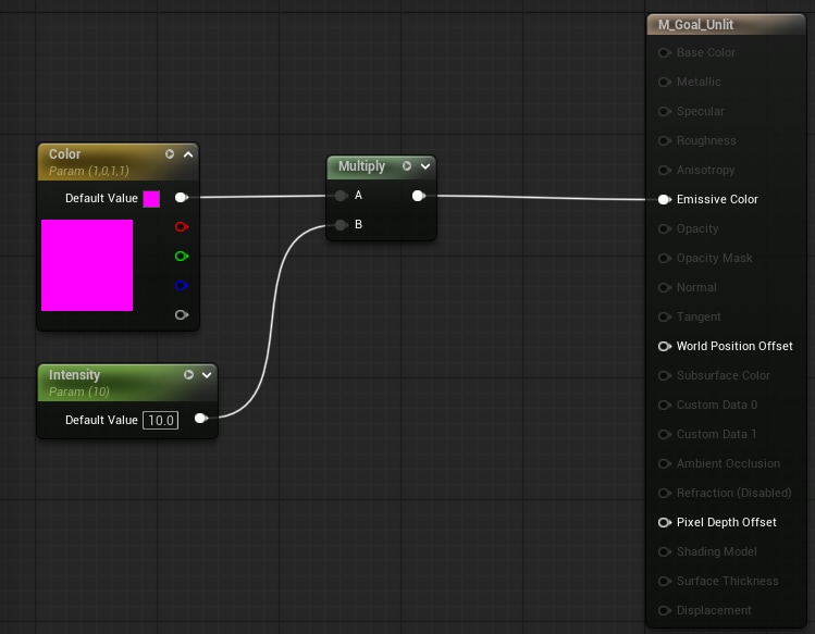
Now, back in BP_PickBlock, we need to set some parameters:
-
Static Mesh is set to Shape_Sphere
-
Under Materials, replace the default with M_Goal_Unlit
-
Change the Collision Presets to match the following:
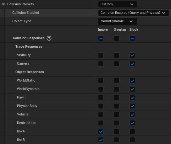
-
Scroll down to the Pick Block section
-
Under Materials, set the Red, Yellow, and Blue materials to M_Goal_Unlit.
Creating the Environment
-
Create a new blueprint labeled “BP_XArmEnv”
-
When the popup window opens, drop down “All Classes” and search for “Gym”
-
Select the Gym Connector Manager
-
-
Go to Class Settings
-
Under Interfaces, go to Implemented Interfaces
-
Search for and add Single Agent Schola Environment
-
The interfaces should be populated with five items now.
-
As we did for PickBlock, we are going to need to add two new C++ files.
-
Call them “XArmEnvComponent”, keep them public and in the same location as the PickBlock source files.
-
Paste in the provided code for XArmEnvComponent.h/.cpp
-
Compile these changes, and reopen Unreal Engine
-
In the components menu, add a new component by searching for XArm, select XArm Env. Call it “XArmEnvComp”
Add the following variables:
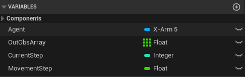
Now, under interfaces, double click on SetEnvironmentOptions and SeedEnvironment. They should both show up in the EventGraph. Then, wire them both up as follows:
We have several functions to setup now. Follow the Blueprints to set them up
-
ComputeReward
Begin Object Class=/Script/BlueprintGraph.K2Node_FunctionEntry Name="K2Node_FunctionEntry_0" ExportPath="/Script/BlueprintGraph.K2Node_FunctionEntry'/Game/Examples/XArm-2/Blueprints/BP_XArmEnv.BP_XArmEnv:ComputeReward.K2Node_FunctionEntry_0'" ExtraFlags=201457664 FunctionReference=(MemberName="ComputeReward") bIsEditable=True NodePosX=-320 NodeGuid=A469E9444FDF5CF9DBDF5F9A5D8407A7 CustomProperties Pin (PinId=8E8C2FE24BEAF660865E168CD8A452A2,PinName="then",Direction="EGPD_Output",PinType.PinCategory="exec",PinType.PinSubCategory="",PinType.PinSubCategoryObject=None,PinType.PinSubCategoryMemberReference=(),PinType.PinValueType=(),PinType.ContainerType=None,PinType.bIsReference=False,PinType.bIsConst=False,PinType.bIsWeakPointer=False,PinType.bIsUObjectWrapper=False,PinType.bSerializeAsSinglePrecisionFloat=False,LinkedTo=(K2Node_FunctionResult_0 8708B444435C80983985BB96ACCA48E8,),PersistentGuid=00000000000000000000000000000000,bHidden=False,bNotConnectable=False,bDefaultValueIsReadOnly=False,bDefaultValueIsIgnored=False,bAdvancedView=False,bOrphanedPin=False,) End Object Begin Object Class=/Script/BlueprintGraph.K2Node_FunctionResult Name="K2Node_FunctionResult_0" ExportPath="/Script/BlueprintGraph.K2Node_FunctionResult'/Game/Examples/XArm-2/Blueprints/BP_XArmEnv.BP_XArmEnv:ComputeReward.K2Node_FunctionResult_0'" FunctionReference=(MemberName="ComputeReward") bIsEditable=True NodePosX=400 NodeGuid=57FDEEB648FC658589C347803C8CEE1C CustomProperties Pin (PinId=8708B444435C80983985BB96ACCA48E8,PinName="execute",PinType.PinCategory="exec",PinType.PinSubCategory="",PinType.PinSubCategoryObject=None,PinType.PinSubCategoryMemberReference=(),PinType.PinValueType=(),PinType.ContainerType=None,PinType.bIsReference=False,PinType.bIsConst=False,PinType.bIsWeakPointer=False,PinType.bIsUObjectWrapper=False,PinType.bSerializeAsSinglePrecisionFloat=False,LinkedTo=(K2Node_FunctionEntry_0 8E8C2FE24BEAF660865E168CD8A452A2,),PersistentGuid=00000000000000000000000000000000,bHidden=False,bNotConnectable=False,bDefaultValueIsReadOnly=False,bDefaultValueIsIgnored=False,bAdvancedView=False,bOrphanedPin=False,) CustomProperties Pin (PinId=A69855FF4BDBDA850CAC158954E2FF08,PinName="OutReward",PinType.PinCategory="real",PinType.PinSubCategory="double",PinType.PinSubCategoryObject=None,PinType.PinSubCategoryMemberReference=(),PinType.PinValueType=(),PinType.ContainerType=None,PinType.bIsReference=False,PinType.bIsConst=False,PinType.bIsWeakPointer=False,PinType.bIsUObjectWrapper=False,PinType.bSerializeAsSinglePrecisionFloat=False,DefaultValue="0.0",AutogeneratedDefaultValue="0.0",LinkedTo=(K2Node_CallFunction_0 E587DE1D4203DA17F8BCC8A0F047BFED,),PersistentGuid=00000000000000000000000000000000,bHidden=False,bNotConnectable=False,bDefaultValueIsReadOnly=False,bDefaultValueIsIgnored=False,bAdvancedView=False,bOrphanedPin=False,) CustomProperties UserDefinedPin (PinName="OutReward",PinType=(PinCategory="real",PinSubCategory="double"),DesiredPinDirection=EGPD_Input,PinDefaultValue="0.0") End Object Begin Object Class=/Script/BlueprintGraph.K2Node_VariableGet Name="K2Node_VariableGet_0" ExportPath="/Script/BlueprintGraph.K2Node_VariableGet'/Game/Examples/XArm-2/Blueprints/BP_XArmEnv.BP_XArmEnv:ComputeReward.K2Node_VariableGet_0'" VariableReference=(MemberName="XArmEnvComp",bSelfContext=True) NodePosX=-128 NodePosY=134 NodeGuid=BF8E3F6849E548881071FF8F2DEBB71E CustomProperties Pin (PinId=AA9413904AFCBBF8E1B2ED800D00B2E3,PinName="XArmEnvComp",Direction="EGPD_Output",PinType.PinCategory="object",PinType.PinSubCategory="",PinType.PinSubCategoryObject="/Script/CoreUObject.Class'/Script/ScholaExamples.XArmEnvComp'",PinType.PinSubCategoryMemberReference=(),PinType.PinValueType=(),PinType.ContainerType=None,PinType.bIsReference=False,PinType.bIsConst=False,PinType.bIsWeakPointer=False,PinType.bIsUObjectWrapper=False,PinType.bSerializeAsSinglePrecisionFloat=False,LinkedTo=(K2Node_CallFunction_0 307D27984990BA889A3A6FBE909D5C66,),PersistentGuid=00000000000000000000000000000000,bHidden=False,bNotConnectable=False,bDefaultValueIsReadOnly=False,bDefaultValueIsIgnored=False,bAdvancedView=False,bOrphanedPin=False,) CustomProperties Pin (PinId=6B88E7834DBBE9DA6F21D992AD504BB1,PinName="self",PinFriendlyName=NSLOCTEXT("K2Node", "Target", "Target"),PinType.PinCategory="object",PinType.PinSubCategory="",PinType.PinSubCategoryObject="/Script/Engine.BlueprintGeneratedClass'/Game/Examples/XArm-2/Blueprints/BP_XArmEnv.BP_XArmEnv_C'",PinType.PinSubCategoryMemberReference=(),PinType.PinValueType=(),PinType.ContainerType=None,PinType.bIsReference=False,PinType.bIsConst=False,PinType.bIsWeakPointer=False,PinType.bIsUObjectWrapper=False,PinType.bSerializeAsSinglePrecisionFloat=False,PersistentGuid=00000000000000000000000000000000,bHidden=True,bNotConnectable=False,bDefaultValueIsReadOnly=False,bDefaultValueIsIgnored=False,bAdvancedView=False,bOrphanedPin=False,) End Object Begin Object Class=/Script/BlueprintGraph.K2Node_CallFunction Name="K2Node_CallFunction_0" ExportPath="/Script/BlueprintGraph.K2Node_CallFunction'/Game/Examples/XArm-2/Blueprints/BP_XArmEnv.BP_XArmEnv:ComputeReward.K2Node_CallFunction_0'" bDefaultsToPureFunc=True FunctionReference=(MemberParent="/Script/CoreUObject.Class'/Script/ScholaExamples.XArmEnvComp'",MemberName="ComputeReward") NodePosX=80 NodePosY=96 NodeGuid=E7D211CC40B828C187CF2EAC6C916D30 CustomProperties Pin (PinId=307D27984990BA889A3A6FBE909D5C66,PinName="self",PinFriendlyName=NSLOCTEXT("K2Node", "Target", "Target"),PinType.PinCategory="object",PinType.PinSubCategory="",PinType.PinSubCategoryObject="/Script/CoreUObject.Class'/Script/ScholaExamples.XArmEnvComp'",PinType.PinSubCategoryMemberReference=(),PinType.PinValueType=(),PinType.ContainerType=None,PinType.bIsReference=False,PinType.bIsConst=False,PinType.bIsWeakPointer=False,PinType.bIsUObjectWrapper=False,PinType.bSerializeAsSinglePrecisionFloat=False,LinkedTo=(K2Node_VariableGet_0 AA9413904AFCBBF8E1B2ED800D00B2E3,),PersistentGuid=00000000000000000000000000000000,bHidden=False,bNotConnectable=False,bDefaultValueIsReadOnly=False,bDefaultValueIsIgnored=False,bAdvancedView=False,bOrphanedPin=False,) CustomProperties Pin (PinId=E587DE1D4203DA17F8BCC8A0F047BFED,PinName="OutReward",Direction="EGPD_Output",PinType.PinCategory="real",PinType.PinSubCategory="float",PinType.PinSubCategoryObject=None,PinType.PinSubCategoryMemberReference=(),PinType.PinValueType=(),PinType.ContainerType=None,PinType.bIsReference=False,PinType.bIsConst=False,PinType.bIsWeakPointer=False,PinType.bIsUObjectWrapper=False,PinType.bSerializeAsSinglePrecisionFloat=False,DefaultValue="0.0",AutogeneratedDefaultValue="0.0",LinkedTo=(K2Node_FunctionResult_0 A69855FF4BDBDA850CAC158954E2FF08,),PersistentGuid=00000000000000000000000000000000,bHidden=False,bNotConnectable=False,bDefaultValueIsReadOnly=False,bDefaultValueIsIgnored=False,bAdvancedView=False,bOrphanedPin=False,) CustomProperties Pin (PinId=D0CE73C7456D774D2E84A0897116915F,PinName="bOutDone",Direction="EGPD_Output",PinType.PinCategory="bool",PinType.PinSubCategory="",PinType.PinSubCategoryObject=None,PinType.PinSubCategoryMemberReference=(),PinType.PinValueType=(),PinType.ContainerType=None,PinType.bIsReference=False,PinType.bIsConst=False,PinType.bIsWeakPointer=False,PinType.bIsUObjectWrapper=False,PinType.bSerializeAsSinglePrecisionFloat=False,DefaultValue="false",AutogeneratedDefaultValue="false",PersistentGuid=00000000000000000000000000000000,bHidden=False,bNotConnectable=False,bDefaultValueIsReadOnly=False,bDefaultValueIsIgnored=False,bAdvancedView=False,bOrphanedPin=False,) End Object -
ComputeStatus
Begin Object Class=/Script/BlueprintGraph.K2Node_FunctionEntry Name="K2Node_FunctionEntry_0" ExportPath="/Script/BlueprintGraph.K2Node_FunctionEntry'/Game/Examples/XArm-2/Blueprints/BP_XArmEnv.BP_XArmEnv:ComputeStatus.K2Node_FunctionEntry_0'" ExtraFlags=201457664 FunctionReference=(MemberName="ComputeStatus") bIsEditable=True NodeGuid=2B543B5E4A12FDB0174458A576615426 CustomProperties Pin (PinId=BFD3BE5B474C3FB0024FD787020970E3,PinName="then",Direction="EGPD_Output",PinType.PinCategory="exec",PinType.PinSubCategory="",PinType.PinSubCategoryObject=None,PinType.PinSubCategoryMemberReference=(),PinType.PinValueType=(),PinType.ContainerType=None,PinType.bIsReference=False,PinType.bIsConst=False,PinType.bIsWeakPointer=False,PinType.bIsUObjectWrapper=False,PinType.bSerializeAsSinglePrecisionFloat=False,LinkedTo=(K2Node_IfThenElse_0 0A580B0E478D4CA3E31BC09215F016B2,),PersistentGuid=00000000000000000000000000000000,bHidden=False,bNotConnectable=False,bDefaultValueIsReadOnly=False,bDefaultValueIsIgnored=False,bAdvancedView=False,bOrphanedPin=False,) End Object Begin Object Class=/Script/BlueprintGraph.K2Node_VariableGet Name="K2Node_VariableGet_0" ExportPath="/Script/BlueprintGraph.K2Node_VariableGet'/Game/Examples/XArm-2/Blueprints/BP_XArmEnv.BP_XArmEnv:ComputeStatus.K2Node_VariableGet_0'" VariableReference=(MemberName="XArmEnvComp",bSelfContext=True) NodePosX=80 NodePosY=294 NodeGuid=96F960F9498577B95B35E886619493E2 CustomProperties Pin (PinId=139456DE4B564F3D1D6631BF6A77AAD5,PinName="XArmEnvComp",Direction="EGPD_Output",PinType.PinCategory="object",PinType.PinSubCategory="",PinType.PinSubCategoryObject="/Script/CoreUObject.Class'/Script/ScholaExamples.XArmEnvComp'",PinType.PinSubCategoryMemberReference=(),PinType.PinValueType=(),PinType.ContainerType=None,PinType.bIsReference=False,PinType.bIsConst=False,PinType.bIsWeakPointer=False,PinType.bIsUObjectWrapper=False,PinType.bSerializeAsSinglePrecisionFloat=False,LinkedTo=(K2Node_CallFunction_0 F5D06D2140925F2D3A98A89750774F9C,),PersistentGuid=00000000000000000000000000000000,bHidden=False,bNotConnectable=False,bDefaultValueIsReadOnly=False,bDefaultValueIsIgnored=False,bAdvancedView=False,bOrphanedPin=False,) CustomProperties Pin (PinId=90853EDB432586AE225A72BD49693BE0,PinName="self",PinFriendlyName=NSLOCTEXT("K2Node", "Target", "Target"),PinType.PinCategory="object",PinType.PinSubCategory="",PinType.PinSubCategoryObject="/Script/Engine.BlueprintGeneratedClass'/Game/Examples/XArm-2/Blueprints/BP_XArmEnv.BP_XArmEnv_C'",PinType.PinSubCategoryMemberReference=(),PinType.PinValueType=(),PinType.ContainerType=None,PinType.bIsReference=False,PinType.bIsConst=False,PinType.bIsWeakPointer=False,PinType.bIsUObjectWrapper=False,PinType.bSerializeAsSinglePrecisionFloat=False,PersistentGuid=00000000000000000000000000000000,bHidden=True,bNotConnectable=False,bDefaultValueIsReadOnly=False,bDefaultValueIsIgnored=False,bAdvancedView=False,bOrphanedPin=False,) End Object Begin Object Class=/Script/BlueprintGraph.K2Node_CallFunction Name="K2Node_CallFunction_0" ExportPath="/Script/BlueprintGraph.K2Node_CallFunction'/Game/Examples/XArm-2/Blueprints/BP_XArmEnv.BP_XArmEnv:ComputeStatus.K2Node_CallFunction_0'" bDefaultsToPureFunc=True FunctionReference=(MemberParent="/Script/CoreUObject.Class'/Script/ScholaExamples.XArmEnvComp'",MemberName="GetEpisodeLengthSteps") NodePosX=288 NodePosY=256 NodeGuid=120C94594AB81BE53DCB56B4E08FD5AE CustomProperties Pin (PinId=F5D06D2140925F2D3A98A89750774F9C,PinName="self",PinFriendlyName=NSLOCTEXT("K2Node", "Target", "Target"),PinToolTip="Target\nXArm Env Comp Object Reference",PinType.PinCategory="object",PinType.PinSubCategory="",PinType.PinSubCategoryObject="/Script/CoreUObject.Class'/Script/ScholaExamples.XArmEnvComp'",PinType.PinSubCategoryMemberReference=(),PinType.PinValueType=(),PinType.ContainerType=None,PinType.bIsReference=False,PinType.bIsConst=False,PinType.bIsWeakPointer=False,PinType.bIsUObjectWrapper=False,PinType.bSerializeAsSinglePrecisionFloat=False,LinkedTo=(K2Node_VariableGet_0 139456DE4B564F3D1D6631BF6A77AAD5,),PersistentGuid=00000000000000000000000000000000,bHidden=False,bNotConnectable=False,bDefaultValueIsReadOnly=False,bDefaultValueIsIgnored=False,bAdvancedView=False,bOrphanedPin=False,) CustomProperties Pin (PinId=4653A1464807463FFCF822879A8372BB,PinName="ReturnValue",PinToolTip="Return Value\nInteger\n\nGet Episode Length Steps",Direction="EGPD_Output",PinType.PinCategory="int",PinType.PinSubCategory="",PinType.PinSubCategoryObject=None,PinType.PinSubCategoryMemberReference=(),PinType.PinValueType=(),PinType.ContainerType=None,PinType.bIsReference=False,PinType.bIsConst=False,PinType.bIsWeakPointer=False,PinType.bIsUObjectWrapper=False,PinType.bSerializeAsSinglePrecisionFloat=False,DefaultValue="0",AutogeneratedDefaultValue="0",LinkedTo=(K2Node_PromotableOperator_0 008B69F447EDDC6A5F6B23B555887A8A,),PersistentGuid=00000000000000000000000000000000,bHidden=False,bNotConnectable=False,bDefaultValueIsReadOnly=False,bDefaultValueIsIgnored=False,bAdvancedView=False,bOrphanedPin=False,) End Object Begin Object Class=/Script/BlueprintGraph.K2Node_VariableGet Name="K2Node_VariableGet_1" ExportPath="/Script/BlueprintGraph.K2Node_VariableGet'/Game/Examples/XArm-2/Blueprints/BP_XArmEnv.BP_XArmEnv:ComputeStatus.K2Node_VariableGet_1'" VariableReference=(MemberName="CurrentStep",MemberGuid=9672A3AC45D1DF60C9460184977E44EC,bSelfContext=True) NodePosX=368 NodePosY=208 NodeGuid=78149DD241F2A2B12D6900AC70C90C9B CustomProperties Pin (PinId=804C26D54E769DF6A079AFB76475B82B,PinName="CurrentStep",Direction="EGPD_Output",PinType.PinCategory="int",PinType.PinSubCategory="",PinType.PinSubCategoryObject=None,PinType.PinSubCategoryMemberReference=(),PinType.PinValueType=(),PinType.ContainerType=None,PinType.bIsReference=False,PinType.bIsConst=False,PinType.bIsWeakPointer=False,PinType.bIsUObjectWrapper=False,PinType.bSerializeAsSinglePrecisionFloat=False,DefaultValue="0",AutogeneratedDefaultValue="0",LinkedTo=(K2Node_PromotableOperator_0 E764697C4BB77DAB9AACDE89B0244918,),PersistentGuid=00000000000000000000000000000000,bHidden=False,bNotConnectable=False,bDefaultValueIsReadOnly=False,bDefaultValueIsIgnored=False,bAdvancedView=False,bOrphanedPin=False,) CustomProperties Pin (PinId=BE873E2F44E24D59C1F0EEBBDDE34D98,PinName="self",PinFriendlyName=NSLOCTEXT("K2Node", "Target", "Target"),PinType.PinCategory="object",PinType.PinSubCategory="",PinType.PinSubCategoryObject="/Script/Engine.BlueprintGeneratedClass'/Game/Examples/XArm-2/Blueprints/BP_XArmEnv.BP_XArmEnv_C'",PinType.PinSubCategoryMemberReference=(),PinType.PinValueType=(),PinType.ContainerType=None,PinType.bIsReference=False,PinType.bIsConst=False,PinType.bIsWeakPointer=False,PinType.bIsUObjectWrapper=False,PinType.bSerializeAsSinglePrecisionFloat=False,PersistentGuid=00000000000000000000000000000000,bHidden=True,bNotConnectable=False,bDefaultValueIsReadOnly=False,bDefaultValueIsIgnored=False,bAdvancedView=False,bOrphanedPin=False,) End Object Begin Object Class=/Script/BlueprintGraph.K2Node_PromotableOperator Name="K2Node_PromotableOperator_0" ExportPath="/Script/BlueprintGraph.K2Node_PromotableOperator'/Game/Examples/XArm-2/Blueprints/BP_XArmEnv.BP_XArmEnv:ComputeStatus.K2Node_PromotableOperator_0'" OperationName="GreaterEqual" bDefaultsToPureFunc=True FunctionReference=(MemberParent="/Script/CoreUObject.Class'/Script/Engine.KismetMathLibrary'",MemberName="GreaterEqual_IntInt") NodePosX=624 NodePosY=240 NodeGuid=AB9A969C4CE471157D339784EC6B8D05 CustomProperties Pin (PinId=E764697C4BB77DAB9AACDE89B0244918,PinName="A",PinType.PinCategory="int",PinType.PinSubCategory="",PinType.PinSubCategoryObject=None,PinType.PinSubCategoryMemberReference=(),PinType.PinValueType=(),PinType.ContainerType=None,PinType.bIsReference=False,PinType.bIsConst=False,PinType.bIsWeakPointer=False,PinType.bIsUObjectWrapper=False,PinType.bSerializeAsSinglePrecisionFloat=False,LinkedTo=(K2Node_VariableGet_1 804C26D54E769DF6A079AFB76475B82B,),PersistentGuid=00000000000000000000000000000000,bHidden=False,bNotConnectable=False,bDefaultValueIsReadOnly=False,bDefaultValueIsIgnored=False,bAdvancedView=False,bOrphanedPin=False,) CustomProperties Pin (PinId=008B69F447EDDC6A5F6B23B555887A8A,PinName="B",PinType.PinCategory="int",PinType.PinSubCategory="",PinType.PinSubCategoryObject=None,PinType.PinSubCategoryMemberReference=(),PinType.PinValueType=(),PinType.ContainerType=None,PinType.bIsReference=False,PinType.bIsConst=False,PinType.bIsWeakPointer=False,PinType.bIsUObjectWrapper=False,PinType.bSerializeAsSinglePrecisionFloat=False,LinkedTo=(K2Node_CallFunction_0 4653A1464807463FFCF822879A8372BB,),PersistentGuid=00000000000000000000000000000000,bHidden=False,bNotConnectable=False,bDefaultValueIsReadOnly=False,bDefaultValueIsIgnored=False,bAdvancedView=False,bOrphanedPin=False,) CustomProperties Pin (PinId=9D118A3F4DC3FD81CCABAD8BAF0EBF86,PinName="ReturnValue",Direction="EGPD_Output",PinType.PinCategory="bool",PinType.PinSubCategory="",PinType.PinSubCategoryObject=None,PinType.PinSubCategoryMemberReference=(),PinType.PinValueType=(),PinType.ContainerType=None,PinType.bIsReference=False,PinType.bIsConst=False,PinType.bIsWeakPointer=False,PinType.bIsUObjectWrapper=False,PinType.bSerializeAsSinglePrecisionFloat=False,LinkedTo=(K2Node_IfThenElse_0 442412174BE0AB29F0A8F1A59C8E9E2C,),PersistentGuid=00000000000000000000000000000000,bHidden=False,bNotConnectable=False,bDefaultValueIsReadOnly=False,bDefaultValueIsIgnored=False,bAdvancedView=False,bOrphanedPin=False,) CustomProperties Pin (PinId=F08CDDD540CBBAD816F0ACAD119461FD,PinName="ErrorTolerance",PinType.PinCategory="",PinType.PinSubCategory="",PinType.PinSubCategoryObject=None,PinType.PinSubCategoryMemberReference=(),PinType.PinValueType=(),PinType.ContainerType=None,PinType.bIsReference=False,PinType.bIsConst=False,PinType.bIsWeakPointer=False,PinType.bIsUObjectWrapper=False,PinType.bSerializeAsSinglePrecisionFloat=False,PersistentGuid=00000000000000000000000000000000,bHidden=True,bNotConnectable=False,bDefaultValueIsReadOnly=False,bDefaultValueIsIgnored=False,bAdvancedView=False,bOrphanedPin=False,) End Object Begin Object Class=/Script/BlueprintGraph.K2Node_IfThenElse Name="K2Node_IfThenElse_0" ExportPath="/Script/BlueprintGraph.K2Node_IfThenElse'/Game/Examples/XArm-2/Blueprints/BP_XArmEnv.BP_XArmEnv:ComputeStatus.K2Node_IfThenElse_0'" NodePosX=800 NodeGuid=E065CE674E04FAD79D4572BA324A0F9B CustomProperties Pin (PinId=0A580B0E478D4CA3E31BC09215F016B2,PinName="execute",PinType.PinCategory="exec",PinType.PinSubCategory="",PinType.PinSubCategoryObject=None,PinType.PinSubCategoryMemberReference=(),PinType.PinValueType=(),PinType.ContainerType=None,PinType.bIsReference=False,PinType.bIsConst=False,PinType.bIsWeakPointer=False,PinType.bIsUObjectWrapper=False,PinType.bSerializeAsSinglePrecisionFloat=False,LinkedTo=(K2Node_FunctionEntry_0 BFD3BE5B474C3FB0024FD787020970E3,),PersistentGuid=00000000000000000000000000000000,bHidden=False,bNotConnectable=False,bDefaultValueIsReadOnly=False,bDefaultValueIsIgnored=False,bAdvancedView=False,bOrphanedPin=False,) CustomProperties Pin (PinId=442412174BE0AB29F0A8F1A59C8E9E2C,PinName="Condition",PinType.PinCategory="bool",PinType.PinSubCategory="",PinType.PinSubCategoryObject=None,PinType.PinSubCategoryMemberReference=(),PinType.PinValueType=(),PinType.ContainerType=None,PinType.bIsReference=False,PinType.bIsConst=False,PinType.bIsWeakPointer=False,PinType.bIsUObjectWrapper=False,PinType.bSerializeAsSinglePrecisionFloat=False,DefaultValue="true",AutogeneratedDefaultValue="true",LinkedTo=(K2Node_PromotableOperator_0 9D118A3F4DC3FD81CCABAD8BAF0EBF86,),PersistentGuid=00000000000000000000000000000000,bHidden=False,bNotConnectable=False,bDefaultValueIsReadOnly=False,bDefaultValueIsIgnored=False,bAdvancedView=False,bOrphanedPin=False,) CustomProperties Pin (PinId=CC5681C2490C8FBCBE91368F04E280F1,PinName="then",PinFriendlyName=NSLOCTEXT("K2Node", "true", "true"),Direction="EGPD_Output",PinType.PinCategory="exec",PinType.PinSubCategory="",PinType.PinSubCategoryObject=None,PinType.PinSubCategoryMemberReference=(),PinType.PinValueType=(),PinType.ContainerType=None,PinType.bIsReference=False,PinType.bIsConst=False,PinType.bIsWeakPointer=False,PinType.bIsUObjectWrapper=False,PinType.bSerializeAsSinglePrecisionFloat=False,LinkedTo=(K2Node_CallFunction_2 AEFCF1244A72843C400238A1C486790D,),PersistentGuid=00000000000000000000000000000000,bHidden=False,bNotConnectable=False,bDefaultValueIsReadOnly=False,bDefaultValueIsIgnored=False,bAdvancedView=False,bOrphanedPin=False,) CustomProperties Pin (PinId=20566BA34FA5DD78B501669F0C2EA83E,PinName="else",PinFriendlyName=NSLOCTEXT("K2Node", "false", "false"),Direction="EGPD_Output",PinType.PinCategory="exec",PinType.PinSubCategory="",PinType.PinSubCategoryObject=None,PinType.PinSubCategoryMemberReference=(),PinType.PinValueType=(),PinType.ContainerType=None,PinType.bIsReference=False,PinType.bIsConst=False,PinType.bIsWeakPointer=False,PinType.bIsUObjectWrapper=False,PinType.bSerializeAsSinglePrecisionFloat=False,LinkedTo=(K2Node_SwitchEnum_0 16B7E08C49EC75F753705AABD8962EF2,),PersistentGuid=00000000000000000000000000000000,bHidden=False,bNotConnectable=False,bDefaultValueIsReadOnly=False,bDefaultValueIsIgnored=False,bAdvancedView=False,bOrphanedPin=False,) End Object Begin Object Class=/Script/BlueprintGraph.K2Node_SwitchEnum Name="K2Node_SwitchEnum_0" ExportPath="/Script/BlueprintGraph.K2Node_SwitchEnum'/Game/Examples/XArm-2/Blueprints/BP_XArmEnv.BP_XArmEnv:ComputeStatus.K2Node_SwitchEnum_0'" Enum="/Script/CoreUObject.Enum'/Script/ScholaExamples.EXArmEnvCompDoneReason'" EnumEntries(0)="" EnumEntries(1)="TargetPicked" EnumEntries(2)="WrongPick" EnumEntries(3)="StepLimit" EnumEntries(4)="OutOfBounds" NodePosX=1120 NodePosY=32 NodeGuid=31BD2D7C4C308D7CC4D957B5453872C2 CustomProperties Pin (PinId=16B7E08C49EC75F753705AABD8962EF2,PinName="execute",PinType.PinCategory="exec",PinType.PinSubCategory="",PinType.PinSubCategoryObject=None,PinType.PinSubCategoryMemberReference=(),PinType.PinValueType=(),PinType.ContainerType=None,PinType.bIsReference=False,PinType.bIsConst=False,PinType.bIsWeakPointer=False,PinType.bIsUObjectWrapper=False,PinType.bSerializeAsSinglePrecisionFloat=False,LinkedTo=(K2Node_IfThenElse_0 20566BA34FA5DD78B501669F0C2EA83E,),PersistentGuid=00000000000000000000000000000000,bHidden=False,bNotConnectable=False,bDefaultValueIsReadOnly=False,bDefaultValueIsIgnored=False,bAdvancedView=False,bOrphanedPin=False,) CustomProperties Pin (PinId=11FAA63A46010AED4FD9BFAA47712151,PinName="Selection",PinType.PinCategory="byte",PinType.PinSubCategory="",PinType.PinSubCategoryObject="/Script/CoreUObject.Enum'/Script/ScholaExamples.EXArmEnvCompDoneReason'",PinType.PinSubCategoryMemberReference=(),PinType.PinValueType=(),PinType.ContainerType=None,PinType.bIsReference=False,PinType.bIsConst=False,PinType.bIsWeakPointer=False,PinType.bIsUObjectWrapper=False,PinType.bSerializeAsSinglePrecisionFloat=False,DefaultValue="None",LinkedTo=(K2Node_CallFunction_1 D122CDC549937A425D3BD19C58BF4496,),PersistentGuid=00000000000000000000000000000000,bHidden=False,bNotConnectable=False,bDefaultValueIsReadOnly=False,bDefaultValueIsIgnored=False,bAdvancedView=False,bOrphanedPin=False,) CustomProperties Pin (PinId=27A3790440CEFF92B57D348710B476D0,PinName="NotEqual_ByteByte",PinType.PinCategory="object",PinType.PinSubCategory="",PinType.PinSubCategoryObject="/Script/CoreUObject.Class'/Script/Engine.KismetMathLibrary'",PinType.PinSubCategoryMemberReference=(),PinType.PinValueType=(),PinType.ContainerType=None,PinType.bIsReference=False,PinType.bIsConst=False,PinType.bIsWeakPointer=False,PinType.bIsUObjectWrapper=False,PinType.bSerializeAsSinglePrecisionFloat=False,DefaultObject="/Script/Engine.Default__KismetMathLibrary",PersistentGuid=00000000000000000000000000000000,bHidden=True,bNotConnectable=True,bDefaultValueIsReadOnly=True,bDefaultValueIsIgnored=False,bAdvancedView=False,bOrphanedPin=False,) CustomProperties Pin (PinId=E3531BBF42C924168995E28E2996FBA1,PinFriendlyName=NSLOCTEXT("UObjectDisplayNames", "EXArmEnvCompDoneReason.None", "None"),Direction="EGPD_Output",PinType.PinCategory="exec",PinType.PinSubCategory="",PinType.PinSubCategoryObject=None,PinType.PinSubCategoryMemberReference=(),PinType.PinValueType=(),PinType.ContainerType=None,PinType.bIsReference=False,PinType.bIsConst=False,PinType.bIsWeakPointer=False,PinType.bIsUObjectWrapper=False,PinType.bSerializeAsSinglePrecisionFloat=False,LinkedTo=(K2Node_FunctionResult_2 F3B045584AB133AB96A00C85CE096282,),PersistentGuid=00000000000000000000000000000000,bHidden=False,bNotConnectable=False,bDefaultValueIsReadOnly=False,bDefaultValueIsIgnored=False,bAdvancedView=False,bOrphanedPin=False,) CustomProperties Pin (PinId=FDDEA78842AAC511FFED7C99CFD11334,PinName="TargetPicked",PinFriendlyName=NSLOCTEXT("UObjectDisplayNames", "EXArmEnvCompDoneReason.TargetPicked", "TargetPicked"),Direction="EGPD_Output",PinType.PinCategory="exec",PinType.PinSubCategory="",PinType.PinSubCategoryObject=None,PinType.PinSubCategoryMemberReference=(),PinType.PinValueType=(),PinType.ContainerType=None,PinType.bIsReference=False,PinType.bIsConst=False,PinType.bIsWeakPointer=False,PinType.bIsUObjectWrapper=False,PinType.bSerializeAsSinglePrecisionFloat=False,LinkedTo=(K2Node_CallFunction_4 77E328F84B2BCFF07DE78686A510DDCC,),PersistentGuid=00000000000000000000000000000000,bHidden=False,bNotConnectable=False,bDefaultValueIsReadOnly=False,bDefaultValueIsIgnored=False,bAdvancedView=False,bOrphanedPin=False,) CustomProperties Pin (PinId=70A9B1F7468498BB370BA588871382B1,PinName="WrongPick",PinFriendlyName=NSLOCTEXT("UObjectDisplayNames", "EXArmEnvCompDoneReason.WrongPick", "WrongPick"),Direction="EGPD_Output",PinType.PinCategory="exec",PinType.PinSubCategory="",PinType.PinSubCategoryObject=None,PinType.PinSubCategoryMemberReference=(),PinType.PinValueType=(),PinType.ContainerType=None,PinType.bIsReference=False,PinType.bIsConst=False,PinType.bIsWeakPointer=False,PinType.bIsUObjectWrapper=False,PinType.bSerializeAsSinglePrecisionFloat=False,LinkedTo=(K2Node_CallFunction_5 77E328F84B2BCFF07DE78686A510DDCC,),PersistentGuid=00000000000000000000000000000000,bHidden=False,bNotConnectable=False,bDefaultValueIsReadOnly=False,bDefaultValueIsIgnored=False,bAdvancedView=False,bOrphanedPin=False,) CustomProperties Pin (PinId=F48C19CE42AF126B5828FDAA42460129,PinName="StepLimit",PinFriendlyName=NSLOCTEXT("UObjectDisplayNames", "EXArmEnvCompDoneReason.StepLimit", "StepLimit"),Direction="EGPD_Output",PinType.PinCategory="exec",PinType.PinSubCategory="",PinType.PinSubCategoryObject=None,PinType.PinSubCategoryMemberReference=(),PinType.PinValueType=(),PinType.ContainerType=None,PinType.bIsReference=False,PinType.bIsConst=False,PinType.bIsWeakPointer=False,PinType.bIsUObjectWrapper=False,PinType.bSerializeAsSinglePrecisionFloat=False,LinkedTo=(K2Node_CallFunction_6 77E328F84B2BCFF07DE78686A510DDCC,),PersistentGuid=00000000000000000000000000000000,bHidden=False,bNotConnectable=False,bDefaultValueIsReadOnly=False,bDefaultValueIsIgnored=False,bAdvancedView=False,bOrphanedPin=False,) CustomProperties Pin (PinId=672827F34C904F63DE0C35802BA00E80,PinName="OutOfBounds",PinFriendlyName=NSLOCTEXT("UObjectDisplayNames", "EXArmEnvCompDoneReason.OutOfBounds", "OutOfBounds"),Direction="EGPD_Output",PinType.PinCategory="exec",PinType.PinSubCategory="",PinType.PinSubCategoryObject=None,PinType.PinSubCategoryMemberReference=(),PinType.PinValueType=(),PinType.ContainerType=None,PinType.bIsReference=False,PinType.bIsConst=False,PinType.bIsWeakPointer=False,PinType.bIsUObjectWrapper=False,PinType.bSerializeAsSinglePrecisionFloat=False,LinkedTo=(K2Node_CallFunction_3 77E328F84B2BCFF07DE78686A510DDCC,),PersistentGuid=00000000000000000000000000000000,bHidden=False,bNotConnectable=False,bDefaultValueIsReadOnly=False,bDefaultValueIsIgnored=False,bAdvancedView=False,bOrphanedPin=False,) End Object Begin Object Class=/Script/BlueprintGraph.K2Node_VariableGet Name="K2Node_VariableGet_2" ExportPath="/Script/BlueprintGraph.K2Node_VariableGet'/Game/Examples/XArm-2/Blueprints/BP_XArmEnv.BP_XArmEnv:ComputeStatus.K2Node_VariableGet_2'" VariableReference=(MemberName="XArmEnvComp",bSelfContext=True) NodePosX=368 NodePosY=390 NodeGuid=BCF51EA1401B2B12CB37BF85FAC8EEBD CustomProperties Pin (PinId=71D063E7492B6D9CE7879F9D7F3E2399,PinName="XArmEnvComp",Direction="EGPD_Output",PinType.PinCategory="object",PinType.PinSubCategory="",PinType.PinSubCategoryObject="/Script/CoreUObject.Class'/Script/ScholaExamples.XArmEnvComp'",PinType.PinSubCategoryMemberReference=(),PinType.PinValueType=(),PinType.ContainerType=None,PinType.bIsReference=False,PinType.bIsConst=False,PinType.bIsWeakPointer=False,PinType.bIsUObjectWrapper=False,PinType.bSerializeAsSinglePrecisionFloat=False,LinkedTo=(K2Node_CallFunction_1 CFDF977248D9C9D6A580B7B87561C939,),PersistentGuid=00000000000000000000000000000000,bHidden=False,bNotConnectable=False,bDefaultValueIsReadOnly=False,bDefaultValueIsIgnored=False,bAdvancedView=False,bOrphanedPin=False,) CustomProperties Pin (PinId=C954E5DD48753E2A84B13591C5CFC433,PinName="self",PinFriendlyName=NSLOCTEXT("K2Node", "Target", "Target"),PinType.PinCategory="object",PinType.PinSubCategory="",PinType.PinSubCategoryObject="/Script/Engine.BlueprintGeneratedClass'/Game/Examples/XArm-2/Blueprints/BP_XArmEnv.BP_XArmEnv_C'",PinType.PinSubCategoryMemberReference=(),PinType.PinValueType=(),PinType.ContainerType=None,PinType.bIsReference=False,PinType.bIsConst=False,PinType.bIsWeakPointer=False,PinType.bIsUObjectWrapper=False,PinType.bSerializeAsSinglePrecisionFloat=False,PersistentGuid=00000000000000000000000000000000,bHidden=True,bNotConnectable=False,bDefaultValueIsReadOnly=False,bDefaultValueIsIgnored=False,bAdvancedView=False,bOrphanedPin=False,) End Object Begin Object Class=/Script/BlueprintGraph.K2Node_CallFunction Name="K2Node_CallFunction_1" ExportPath="/Script/BlueprintGraph.K2Node_CallFunction'/Game/Examples/XArm-2/Blueprints/BP_XArmEnv.BP_XArmEnv:ComputeStatus.K2Node_CallFunction_1'" bDefaultsToPureFunc=True FunctionReference=(MemberParent="/Script/CoreUObject.Class'/Script/ScholaExamples.XArmEnvComp'",MemberName="GetDoneReason") NodePosX=560 NodePosY=352 NodeGuid=AE4C19E64A05C15C0C45708EED0C68F9 CustomProperties Pin (PinId=CFDF977248D9C9D6A580B7B87561C939,PinName="self",PinFriendlyName=NSLOCTEXT("K2Node", "Target", "Target"),PinToolTip="Target\nXArm Env Comp Object Reference",PinType.PinCategory="object",PinType.PinSubCategory="",PinType.PinSubCategoryObject="/Script/CoreUObject.Class'/Script/ScholaExamples.XArmEnvComp'",PinType.PinSubCategoryMemberReference=(),PinType.PinValueType=(),PinType.ContainerType=None,PinType.bIsReference=False,PinType.bIsConst=False,PinType.bIsWeakPointer=False,PinType.bIsUObjectWrapper=False,PinType.bSerializeAsSinglePrecisionFloat=False,LinkedTo=(K2Node_VariableGet_2 71D063E7492B6D9CE7879F9D7F3E2399,),PersistentGuid=00000000000000000000000000000000,bHidden=False,bNotConnectable=False,bDefaultValueIsReadOnly=False,bDefaultValueIsIgnored=False,bAdvancedView=False,bOrphanedPin=False,) CustomProperties Pin (PinId=D122CDC549937A425D3BD19C58BF4496,PinName="ReturnValue",PinToolTip="Return Value\nEXArmEnvCompDoneReason Enum\n\nGet Done Reason",Direction="EGPD_Output",PinType.PinCategory="byte",PinType.PinSubCategory="",PinType.PinSubCategoryObject="/Script/CoreUObject.Enum'/Script/ScholaExamples.EXArmEnvCompDoneReason'",PinType.PinSubCategoryMemberReference=(),PinType.PinValueType=(),PinType.ContainerType=None,PinType.bIsReference=False,PinType.bIsConst=False,PinType.bIsWeakPointer=False,PinType.bIsUObjectWrapper=False,PinType.bSerializeAsSinglePrecisionFloat=False,DefaultValue="None",LinkedTo=(K2Node_SwitchEnum_0 11FAA63A46010AED4FD9BFAA47712151,),PersistentGuid=00000000000000000000000000000000,bHidden=False,bNotConnectable=False,bDefaultValueIsReadOnly=False,bDefaultValueIsIgnored=False,bAdvancedView=False,bOrphanedPin=False,) End Object Begin Object Class=/Script/BlueprintGraph.K2Node_CallFunction Name="K2Node_CallFunction_2" ExportPath="/Script/BlueprintGraph.K2Node_CallFunction'/Game/Examples/XArm-2/Blueprints/BP_XArmEnv.BP_XArmEnv:ComputeStatus.K2Node_CallFunction_2'" FunctionReference=(MemberParent="/Script/CoreUObject.Class'/Script/ScholaExamples.XArmEnvComp'",MemberName="ForceDone") NodePosX=1120 NodePosY=-160 NodeGuid=468F0B7B4B3A4EB6A2041BA6B825300F CustomProperties Pin (PinId=AEFCF1244A72843C400238A1C486790D,PinName="execute",PinType.PinCategory="exec",PinType.PinSubCategory="",PinType.PinSubCategoryObject=None,PinType.PinSubCategoryMemberReference=(),PinType.PinValueType=(),PinType.ContainerType=None,PinType.bIsReference=False,PinType.bIsConst=False,PinType.bIsWeakPointer=False,PinType.bIsUObjectWrapper=False,PinType.bSerializeAsSinglePrecisionFloat=False,LinkedTo=(K2Node_IfThenElse_0 CC5681C2490C8FBCBE91368F04E280F1,),PersistentGuid=00000000000000000000000000000000,bHidden=False,bNotConnectable=False,bDefaultValueIsReadOnly=False,bDefaultValueIsIgnored=False,bAdvancedView=False,bOrphanedPin=False,) CustomProperties Pin (PinId=B9BD57DF4DCA6646AF62A097A7DA33AE,PinName="then",Direction="EGPD_Output",PinType.PinCategory="exec",PinType.PinSubCategory="",PinType.PinSubCategoryObject=None,PinType.PinSubCategoryMemberReference=(),PinType.PinValueType=(),PinType.ContainerType=None,PinType.bIsReference=False,PinType.bIsConst=False,PinType.bIsWeakPointer=False,PinType.bIsUObjectWrapper=False,PinType.bSerializeAsSinglePrecisionFloat=False,LinkedTo=(K2Node_FunctionResult_1 317EBEA4447495C9C951D49794CF0F62,),PersistentGuid=00000000000000000000000000000000,bHidden=False,bNotConnectable=False,bDefaultValueIsReadOnly=False,bDefaultValueIsIgnored=False,bAdvancedView=False,bOrphanedPin=False,) CustomProperties Pin (PinId=BFD57A714E66C4242CC692B3BFFCE2B8,PinName="self",PinFriendlyName=NSLOCTEXT("K2Node", "Target", "Target"),PinType.PinCategory="object",PinType.PinSubCategory="",PinType.PinSubCategoryObject="/Script/CoreUObject.Class'/Script/ScholaExamples.XArmEnvComp'",PinType.PinSubCategoryMemberReference=(),PinType.PinValueType=(),PinType.ContainerType=None,PinType.bIsReference=False,PinType.bIsConst=False,PinType.bIsWeakPointer=False,PinType.bIsUObjectWrapper=False,PinType.bSerializeAsSinglePrecisionFloat=False,LinkedTo=(K2Node_VariableGet_3 62C8F4BA4E460514829307B4E271787B,),PersistentGuid=00000000000000000000000000000000,bHidden=False,bNotConnectable=False,bDefaultValueIsReadOnly=False,bDefaultValueIsIgnored=False,bAdvancedView=False,bOrphanedPin=False,) CustomProperties Pin (PinId=C1F55BE64EB23073D11731941320307E,PinName="Reason",PinType.PinCategory="byte",PinType.PinSubCategory="",PinType.PinSubCategoryObject="/Script/CoreUObject.Enum'/Script/ScholaExamples.EXArmEnvCompDoneReason'",PinType.PinSubCategoryMemberReference=(),PinType.PinValueType=(),PinType.ContainerType=None,PinType.bIsReference=False,PinType.bIsConst=False,PinType.bIsWeakPointer=False,PinType.bIsUObjectWrapper=False,PinType.bSerializeAsSinglePrecisionFloat=False,DefaultValue="StepLimit",AutogeneratedDefaultValue="StepLimit",PersistentGuid=00000000000000000000000000000000,bHidden=False,bNotConnectable=False,bDefaultValueIsReadOnly=False,bDefaultValueIsIgnored=False,bAdvancedView=False,bOrphanedPin=False,) End Object Begin Object Class=/Script/BlueprintGraph.K2Node_VariableGet Name="K2Node_VariableGet_3" ExportPath="/Script/BlueprintGraph.K2Node_VariableGet'/Game/Examples/XArm-2/Blueprints/BP_XArmEnv.BP_XArmEnv:ComputeStatus.K2Node_VariableGet_3'" VariableReference=(MemberName="XArmEnvComp",bSelfContext=True) NodePosX=896 NodePosY=-90 NodeGuid=E115AD4247DD13292601C29FE32A93EA CustomProperties Pin (PinId=62C8F4BA4E460514829307B4E271787B,PinName="XArmEnvComp",Direction="EGPD_Output",PinType.PinCategory="object",PinType.PinSubCategory="",PinType.PinSubCategoryObject="/Script/CoreUObject.Class'/Script/ScholaExamples.XArmEnvComp'",PinType.PinSubCategoryMemberReference=(),PinType.PinValueType=(),PinType.ContainerType=None,PinType.bIsReference=False,PinType.bIsConst=False,PinType.bIsWeakPointer=False,PinType.bIsUObjectWrapper=False,PinType.bSerializeAsSinglePrecisionFloat=False,LinkedTo=(K2Node_CallFunction_2 BFD57A714E66C4242CC692B3BFFCE2B8,),PersistentGuid=00000000000000000000000000000000,bHidden=False,bNotConnectable=False,bDefaultValueIsReadOnly=False,bDefaultValueIsIgnored=False,bAdvancedView=False,bOrphanedPin=False,) CustomProperties Pin (PinId=CBA5B4CE4E380C1C0C76C292F5EFA20A,PinName="self",PinFriendlyName=NSLOCTEXT("K2Node", "Target", "Target"),PinType.PinCategory="object",PinType.PinSubCategory="",PinType.PinSubCategoryObject="/Script/Engine.BlueprintGeneratedClass'/Game/Examples/XArm-2/Blueprints/BP_XArmEnv.BP_XArmEnv_C'",PinType.PinSubCategoryMemberReference=(),PinType.PinValueType=(),PinType.ContainerType=None,PinType.bIsReference=False,PinType.bIsConst=False,PinType.bIsWeakPointer=False,PinType.bIsUObjectWrapper=False,PinType.bSerializeAsSinglePrecisionFloat=False,PersistentGuid=00000000000000000000000000000000,bHidden=True,bNotConnectable=False,bDefaultValueIsReadOnly=False,bDefaultValueIsIgnored=False,bAdvancedView=False,bOrphanedPin=False,) End Object Begin Object Class=/Script/BlueprintGraph.K2Node_FunctionResult Name="K2Node_FunctionResult_1" ExportPath="/Script/BlueprintGraph.K2Node_FunctionResult'/Game/Examples/XArm-2/Blueprints/BP_XArmEnv.BP_XArmEnv:ComputeStatus.K2Node_FunctionResult_1'" FunctionReference=(MemberName="ComputeStatus") bIsEditable=True NodePosX=2048 NodePosY=-144 NodeGuid=88997AFE4FD6015F7454BCAB3047F997 CustomProperties Pin (PinId=317EBEA4447495C9C951D49794CF0F62,PinName="execute",PinType.PinCategory="exec",PinType.PinSubCategory="",PinType.PinSubCategoryObject=None,PinType.PinSubCategoryMemberReference=(),PinType.PinValueType=(),PinType.ContainerType=None,PinType.bIsReference=False,PinType.bIsConst=False,PinType.bIsWeakPointer=False,PinType.bIsUObjectWrapper=False,PinType.bSerializeAsSinglePrecisionFloat=False,LinkedTo=(K2Node_CallFunction_2 B9BD57DF4DCA6646AF62A097A7DA33AE,),PersistentGuid=00000000000000000000000000000000,bHidden=False,bNotConnectable=False,bDefaultValueIsReadOnly=False,bDefaultValueIsIgnored=False,bAdvancedView=False,bOrphanedPin=False,) CustomProperties Pin (PinId=410423014F605726556433897422B3A7,PinName="Completed",PinType.PinCategory="bool",PinType.PinSubCategory="",PinType.PinSubCategoryObject=None,PinType.PinSubCategoryMemberReference=(),PinType.PinValueType=(),PinType.ContainerType=None,PinType.bIsReference=False,PinType.bIsConst=False,PinType.bIsWeakPointer=False,PinType.bIsUObjectWrapper=False,PinType.bSerializeAsSinglePrecisionFloat=False,DefaultValue="false",AutogeneratedDefaultValue="false",PersistentGuid=00000000000000000000000000000000,bHidden=False,bNotConnectable=False,bDefaultValueIsReadOnly=False,bDefaultValueIsIgnored=False,bAdvancedView=False,bOrphanedPin=False,) CustomProperties Pin (PinId=AE32FE19445557F9CEA1CE96B314B51E,PinName="Truncated",PinType.PinCategory="bool",PinType.PinSubCategory="",PinType.PinSubCategoryObject=None,PinType.PinSubCategoryMemberReference=(),PinType.PinValueType=(),PinType.ContainerType=None,PinType.bIsReference=False,PinType.bIsConst=False,PinType.bIsWeakPointer=False,PinType.bIsUObjectWrapper=False,PinType.bSerializeAsSinglePrecisionFloat=False,DefaultValue="true",AutogeneratedDefaultValue="true",PersistentGuid=00000000000000000000000000000000,bHidden=False,bNotConnectable=False,bDefaultValueIsReadOnly=False,bDefaultValueIsIgnored=False,bAdvancedView=False,bOrphanedPin=False,) CustomProperties UserDefinedPin (PinName="Completed",PinType=(PinCategory="bool"),DesiredPinDirection=EGPD_Input,PinDefaultValue="false") CustomProperties UserDefinedPin (PinName="Truncated",PinType=(PinCategory="bool"),DesiredPinDirection=EGPD_Input,PinDefaultValue="true") End Object Begin Object Class=/Script/BlueprintGraph.K2Node_FunctionResult Name="K2Node_FunctionResult_2" ExportPath="/Script/BlueprintGraph.K2Node_FunctionResult'/Game/Examples/XArm-2/Blueprints/BP_XArmEnv.BP_XArmEnv:ComputeStatus.K2Node_FunctionResult_2'" FunctionReference=(MemberName="ComputeStatus") bIsEditable=True NodePosX=2048 NodePosY=32 NodeGuid=D0139A52458963483BC2219D86AF7CE1 CustomProperties Pin (PinId=F3B045584AB133AB96A00C85CE096282,PinName="execute",PinType.PinCategory="exec",PinType.PinSubCategory="",PinType.PinSubCategoryObject=None,PinType.PinSubCategoryMemberReference=(),PinType.PinValueType=(),PinType.ContainerType=None,PinType.bIsReference=False,PinType.bIsConst=False,PinType.bIsWeakPointer=False,PinType.bIsUObjectWrapper=False,PinType.bSerializeAsSinglePrecisionFloat=False,LinkedTo=(K2Node_SwitchEnum_0 E3531BBF42C924168995E28E2996FBA1,),PersistentGuid=00000000000000000000000000000000,bHidden=False,bNotConnectable=False,bDefaultValueIsReadOnly=False,bDefaultValueIsIgnored=False,bAdvancedView=False,bOrphanedPin=False,) CustomProperties Pin (PinId=2A9B5B894D4F542A176F3082ABF6407C,PinName="Completed",PinType.PinCategory="bool",PinType.PinSubCategory="",PinType.PinSubCategoryObject=None,PinType.PinSubCategoryMemberReference=(),PinType.PinValueType=(),PinType.ContainerType=None,PinType.bIsReference=False,PinType.bIsConst=False,PinType.bIsWeakPointer=False,PinType.bIsUObjectWrapper=False,PinType.bSerializeAsSinglePrecisionFloat=False,DefaultValue="false",AutogeneratedDefaultValue="false",PersistentGuid=00000000000000000000000000000000,bHidden=False,bNotConnectable=False,bDefaultValueIsReadOnly=False,bDefaultValueIsIgnored=False,bAdvancedView=False,bOrphanedPin=False,) CustomProperties Pin (PinId=00CAB2EE48D811A4AC5E71814ACC88E9,PinName="Truncated",PinType.PinCategory="bool",PinType.PinSubCategory="",PinType.PinSubCategoryObject=None,PinType.PinSubCategoryMemberReference=(),PinType.PinValueType=(),PinType.ContainerType=None,PinType.bIsReference=False,PinType.bIsConst=False,PinType.bIsWeakPointer=False,PinType.bIsUObjectWrapper=False,PinType.bSerializeAsSinglePrecisionFloat=False,DefaultValue="false",AutogeneratedDefaultValue="false",PersistentGuid=00000000000000000000000000000000,bHidden=False,bNotConnectable=False,bDefaultValueIsReadOnly=False,bDefaultValueIsIgnored=False,bAdvancedView=False,bOrphanedPin=False,) CustomProperties UserDefinedPin (PinName="Completed",PinType=(PinCategory="bool"),DesiredPinDirection=EGPD_Input,PinDefaultValue="false") CustomProperties UserDefinedPin (PinName="Truncated",PinType=(PinCategory="bool"),DesiredPinDirection=EGPD_Input,PinDefaultValue="false") End Object Begin Object Class=/Script/BlueprintGraph.K2Node_CallFunction Name="K2Node_CallFunction_4" ExportPath="/Script/BlueprintGraph.K2Node_CallFunction'/Game/Examples/XArm-2/Blueprints/BP_XArmEnv.BP_XArmEnv:ComputeStatus.K2Node_CallFunction_4'" FunctionReference=(MemberParent="/Script/CoreUObject.Class'/Script/ScholaExamples.XArmEnvComp'",MemberName="ForceDone") NodePosX=1600 NodePosY=176 NodeGuid=495FFECF47411180E79FA3AB0ACD3D05 CustomProperties Pin (PinId=77E328F84B2BCFF07DE78686A510DDCC,PinName="execute",PinType.PinCategory="exec",PinType.PinSubCategory="",PinType.PinSubCategoryObject=None,PinType.PinSubCategoryMemberReference=(),PinType.PinValueType=(),PinType.ContainerType=None,PinType.bIsReference=False,PinType.bIsConst=False,PinType.bIsWeakPointer=False,PinType.bIsUObjectWrapper=False,PinType.bSerializeAsSinglePrecisionFloat=False,LinkedTo=(K2Node_SwitchEnum_0 FDDEA78842AAC511FFED7C99CFD11334,),PersistentGuid=00000000000000000000000000000000,bHidden=False,bNotConnectable=False,bDefaultValueIsReadOnly=False,bDefaultValueIsIgnored=False,bAdvancedView=False,bOrphanedPin=False,) CustomProperties Pin (PinId=C3CEDB814E8912539C469892C732A56E,PinName="then",Direction="EGPD_Output",PinType.PinCategory="exec",PinType.PinSubCategory="",PinType.PinSubCategoryObject=None,PinType.PinSubCategoryMemberReference=(),PinType.PinValueType=(),PinType.ContainerType=None,PinType.bIsReference=False,PinType.bIsConst=False,PinType.bIsWeakPointer=False,PinType.bIsUObjectWrapper=False,PinType.bSerializeAsSinglePrecisionFloat=False,LinkedTo=(K2Node_FunctionResult_3 CC7C46EB48133F65020239AB5058D1F8,),PersistentGuid=00000000000000000000000000000000,bHidden=False,bNotConnectable=False,bDefaultValueIsReadOnly=False,bDefaultValueIsIgnored=False,bAdvancedView=False,bOrphanedPin=False,) CustomProperties Pin (PinId=C8FF634844A6F4DB68ACCE87083C121A,PinName="self",PinFriendlyName=NSLOCTEXT("K2Node", "Target", "Target"),PinType.PinCategory="object",PinType.PinSubCategory="",PinType.PinSubCategoryObject="/Script/CoreUObject.Class'/Script/ScholaExamples.XArmEnvComp'",PinType.PinSubCategoryMemberReference=(),PinType.PinValueType=(),PinType.ContainerType=None,PinType.bIsReference=False,PinType.bIsConst=False,PinType.bIsWeakPointer=False,PinType.bIsUObjectWrapper=False,PinType.bSerializeAsSinglePrecisionFloat=False,LinkedTo=(K2Node_VariableGet_4 AFD954894DD30318A4A6C9BBFDA8098E,),PersistentGuid=00000000000000000000000000000000,bHidden=False,bNotConnectable=False,bDefaultValueIsReadOnly=False,bDefaultValueIsIgnored=False,bAdvancedView=False,bOrphanedPin=False,) CustomProperties Pin (PinId=F5E445E3433E87118003CD96CEA07C8E,PinName="Reason",PinType.PinCategory="byte",PinType.PinSubCategory="",PinType.PinSubCategoryObject="/Script/CoreUObject.Enum'/Script/ScholaExamples.EXArmEnvCompDoneReason'",PinType.PinSubCategoryMemberReference=(),PinType.PinValueType=(),PinType.ContainerType=None,PinType.bIsReference=False,PinType.bIsConst=False,PinType.bIsWeakPointer=False,PinType.bIsUObjectWrapper=False,PinType.bSerializeAsSinglePrecisionFloat=False,DefaultValue="TargetPicked",AutogeneratedDefaultValue="StepLimit",PersistentGuid=00000000000000000000000000000000,bHidden=False,bNotConnectable=False,bDefaultValueIsReadOnly=False,bDefaultValueIsIgnored=False,bAdvancedView=False,bOrphanedPin=False,) End Object Begin Object Class=/Script/BlueprintGraph.K2Node_VariableGet Name="K2Node_VariableGet_4" ExportPath="/Script/BlueprintGraph.K2Node_VariableGet'/Game/Examples/XArm-2/Blueprints/BP_XArmEnv.BP_XArmEnv:ComputeStatus.K2Node_VariableGet_4'" VariableReference=(MemberName="XArmEnvComp",bSelfContext=True) NodePosX=1200 NodePosY=246 NodeGuid=4777CDBC4D1020A2BFA3E7806367FFE8 CustomProperties Pin (PinId=AFD954894DD30318A4A6C9BBFDA8098E,PinName="XArmEnvComp",Direction="EGPD_Output",PinType.PinCategory="object",PinType.PinSubCategory="",PinType.PinSubCategoryObject="/Script/CoreUObject.Class'/Script/ScholaExamples.XArmEnvComp'",PinType.PinSubCategoryMemberReference=(),PinType.PinValueType=(),PinType.ContainerType=None,PinType.bIsReference=False,PinType.bIsConst=False,PinType.bIsWeakPointer=False,PinType.bIsUObjectWrapper=False,PinType.bSerializeAsSinglePrecisionFloat=False,LinkedTo=(K2Node_CallFunction_4 C8FF634844A6F4DB68ACCE87083C121A,K2Node_CallFunction_5 C8FF634844A6F4DB68ACCE87083C121A,K2Node_CallFunction_6 C8FF634844A6F4DB68ACCE87083C121A,K2Node_CallFunction_3 C8FF634844A6F4DB68ACCE87083C121A,),PersistentGuid=00000000000000000000000000000000,bHidden=False,bNotConnectable=False,bDefaultValueIsReadOnly=False,bDefaultValueIsIgnored=False,bAdvancedView=False,bOrphanedPin=False,) CustomProperties Pin (PinId=0C3D36334FE9F2DBC3741B837B3488F2,PinName="self",PinFriendlyName=NSLOCTEXT("K2Node", "Target", "Target"),PinType.PinCategory="object",PinType.PinSubCategory="",PinType.PinSubCategoryObject="/Script/Engine.BlueprintGeneratedClass'/Game/Examples/XArm-2/Blueprints/BP_XArmEnv.BP_XArmEnv_C'",PinType.PinSubCategoryMemberReference=(),PinType.PinValueType=(),PinType.ContainerType=None,PinType.bIsReference=False,PinType.bIsConst=False,PinType.bIsWeakPointer=False,PinType.bIsUObjectWrapper=False,PinType.bSerializeAsSinglePrecisionFloat=False,PersistentGuid=00000000000000000000000000000000,bHidden=True,bNotConnectable=False,bDefaultValueIsReadOnly=False,bDefaultValueIsIgnored=False,bAdvancedView=False,bOrphanedPin=False,) End Object Begin Object Class=/Script/BlueprintGraph.K2Node_FunctionResult Name="K2Node_FunctionResult_3" ExportPath="/Script/BlueprintGraph.K2Node_FunctionResult'/Game/Examples/XArm-2/Blueprints/BP_XArmEnv.BP_XArmEnv:ComputeStatus.K2Node_FunctionResult_3'" FunctionReference=(MemberName="ComputeStatus") bIsEditable=True NodePosX=2048 NodePosY=192 NodeGuid=890040964B88B50C20E8C8BA2DB2140C CustomProperties Pin (PinId=CC7C46EB48133F65020239AB5058D1F8,PinName="execute",PinType.PinCategory="exec",PinType.PinSubCategory="",PinType.PinSubCategoryObject=None,PinType.PinSubCategoryMemberReference=(),PinType.PinValueType=(),PinType.ContainerType=None,PinType.bIsReference=False,PinType.bIsConst=False,PinType.bIsWeakPointer=False,PinType.bIsUObjectWrapper=False,PinType.bSerializeAsSinglePrecisionFloat=False,LinkedTo=(K2Node_CallFunction_4 C3CEDB814E8912539C469892C732A56E,),PersistentGuid=00000000000000000000000000000000,bHidden=False,bNotConnectable=False,bDefaultValueIsReadOnly=False,bDefaultValueIsIgnored=False,bAdvancedView=False,bOrphanedPin=False,) CustomProperties Pin (PinId=EEB6F0A04C403A7742C99887286E9247,PinName="Completed",PinType.PinCategory="bool",PinType.PinSubCategory="",PinType.PinSubCategoryObject=None,PinType.PinSubCategoryMemberReference=(),PinType.PinValueType=(),PinType.ContainerType=None,PinType.bIsReference=False,PinType.bIsConst=False,PinType.bIsWeakPointer=False,PinType.bIsUObjectWrapper=False,PinType.bSerializeAsSinglePrecisionFloat=False,DefaultValue="true",AutogeneratedDefaultValue="true",PersistentGuid=00000000000000000000000000000000,bHidden=False,bNotConnectable=False,bDefaultValueIsReadOnly=False,bDefaultValueIsIgnored=False,bAdvancedView=False,bOrphanedPin=False,) CustomProperties Pin (PinId=4EB28ED94836C3127AEBE7A051FA66A4,PinName="Truncated",PinType.PinCategory="bool",PinType.PinSubCategory="",PinType.PinSubCategoryObject=None,PinType.PinSubCategoryMemberReference=(),PinType.PinValueType=(),PinType.ContainerType=None,PinType.bIsReference=False,PinType.bIsConst=False,PinType.bIsWeakPointer=False,PinType.bIsUObjectWrapper=False,PinType.bSerializeAsSinglePrecisionFloat=False,DefaultValue="false",AutogeneratedDefaultValue="false",PersistentGuid=00000000000000000000000000000000,bHidden=False,bNotConnectable=False,bDefaultValueIsReadOnly=False,bDefaultValueIsIgnored=False,bAdvancedView=False,bOrphanedPin=False,) CustomProperties UserDefinedPin (PinName="Completed",PinType=(PinCategory="bool"),DesiredPinDirection=EGPD_Input,PinDefaultValue="true") CustomProperties UserDefinedPin (PinName="Truncated",PinType=(PinCategory="bool"),DesiredPinDirection=EGPD_Input,PinDefaultValue="false") End Object Begin Object Class=/Script/BlueprintGraph.K2Node_CallFunction Name="K2Node_CallFunction_5" ExportPath="/Script/BlueprintGraph.K2Node_CallFunction'/Game/Examples/XArm-2/Blueprints/BP_XArmEnv.BP_XArmEnv:ComputeStatus.K2Node_CallFunction_5'" FunctionReference=(MemberParent="/Script/CoreUObject.Class'/Script/ScholaExamples.XArmEnvComp'",MemberName="ForceDone") NodePosX=1600 NodePosY=352 NodeGuid=FAD880D04F1EDA8E0A43E3AB3E957C95 CustomProperties Pin (PinId=77E328F84B2BCFF07DE78686A510DDCC,PinName="execute",PinType.PinCategory="exec",PinType.PinSubCategory="",PinType.PinSubCategoryObject=None,PinType.PinSubCategoryMemberReference=(),PinType.PinValueType=(),PinType.ContainerType=None,PinType.bIsReference=False,PinType.bIsConst=False,PinType.bIsWeakPointer=False,PinType.bIsUObjectWrapper=False,PinType.bSerializeAsSinglePrecisionFloat=False,LinkedTo=(K2Node_SwitchEnum_0 70A9B1F7468498BB370BA588871382B1,),PersistentGuid=00000000000000000000000000000000,bHidden=False,bNotConnectable=False,bDefaultValueIsReadOnly=False,bDefaultValueIsIgnored=False,bAdvancedView=False,bOrphanedPin=False,) CustomProperties Pin (PinId=C3CEDB814E8912539C469892C732A56E,PinName="then",Direction="EGPD_Output",PinType.PinCategory="exec",PinType.PinSubCategory="",PinType.PinSubCategoryObject=None,PinType.PinSubCategoryMemberReference=(),PinType.PinValueType=(),PinType.ContainerType=None,PinType.bIsReference=False,PinType.bIsConst=False,PinType.bIsWeakPointer=False,PinType.bIsUObjectWrapper=False,PinType.bSerializeAsSinglePrecisionFloat=False,LinkedTo=(K2Node_FunctionResult_5 DE1C8989461660B316EF2898F24577AC,),PersistentGuid=00000000000000000000000000000000,bHidden=False,bNotConnectable=False,bDefaultValueIsReadOnly=False,bDefaultValueIsIgnored=False,bAdvancedView=False,bOrphanedPin=False,) CustomProperties Pin (PinId=C8FF634844A6F4DB68ACCE87083C121A,PinName="self",PinFriendlyName=NSLOCTEXT("K2Node", "Target", "Target"),PinType.PinCategory="object",PinType.PinSubCategory="",PinType.PinSubCategoryObject="/Script/CoreUObject.Class'/Script/ScholaExamples.XArmEnvComp'",PinType.PinSubCategoryMemberReference=(),PinType.PinValueType=(),PinType.ContainerType=None,PinType.bIsReference=False,PinType.bIsConst=False,PinType.bIsWeakPointer=False,PinType.bIsUObjectWrapper=False,PinType.bSerializeAsSinglePrecisionFloat=False,LinkedTo=(K2Node_VariableGet_4 AFD954894DD30318A4A6C9BBFDA8098E,),PersistentGuid=00000000000000000000000000000000,bHidden=False,bNotConnectable=False,bDefaultValueIsReadOnly=False,bDefaultValueIsIgnored=False,bAdvancedView=False,bOrphanedPin=False,) CustomProperties Pin (PinId=F5E445E3433E87118003CD96CEA07C8E,PinName="Reason",PinType.PinCategory="byte",PinType.PinSubCategory="",PinType.PinSubCategoryObject="/Script/CoreUObject.Enum'/Script/ScholaExamples.EXArmEnvCompDoneReason'",PinType.PinSubCategoryMemberReference=(),PinType.PinValueType=(),PinType.ContainerType=None,PinType.bIsReference=False,PinType.bIsConst=False,PinType.bIsWeakPointer=False,PinType.bIsUObjectWrapper=False,PinType.bSerializeAsSinglePrecisionFloat=False,DefaultValue="WrongPick",AutogeneratedDefaultValue="StepLimit",PersistentGuid=00000000000000000000000000000000,bHidden=False,bNotConnectable=False,bDefaultValueIsReadOnly=False,bDefaultValueIsIgnored=False,bAdvancedView=False,bOrphanedPin=False,) End Object Begin Object Class=/Script/BlueprintGraph.K2Node_CallFunction Name="K2Node_CallFunction_6" ExportPath="/Script/BlueprintGraph.K2Node_CallFunction'/Game/Examples/XArm-2/Blueprints/BP_XArmEnv.BP_XArmEnv:ComputeStatus.K2Node_CallFunction_6'" FunctionReference=(MemberParent="/Script/CoreUObject.Class'/Script/ScholaExamples.XArmEnvComp'",MemberName="ForceDone") NodePosX=1600 NodePosY=528 NodeGuid=472C4716493A787F5B20D0B88E4BBE45 CustomProperties Pin (PinId=77E328F84B2BCFF07DE78686A510DDCC,PinName="execute",PinType.PinCategory="exec",PinType.PinSubCategory="",PinType.PinSubCategoryObject=None,PinType.PinSubCategoryMemberReference=(),PinType.PinValueType=(),PinType.ContainerType=None,PinType.bIsReference=False,PinType.bIsConst=False,PinType.bIsWeakPointer=False,PinType.bIsUObjectWrapper=False,PinType.bSerializeAsSinglePrecisionFloat=False,LinkedTo=(K2Node_SwitchEnum_0 F48C19CE42AF126B5828FDAA42460129,),PersistentGuid=00000000000000000000000000000000,bHidden=False,bNotConnectable=False,bDefaultValueIsReadOnly=False,bDefaultValueIsIgnored=False,bAdvancedView=False,bOrphanedPin=False,) CustomProperties Pin (PinId=C3CEDB814E8912539C469892C732A56E,PinName="then",Direction="EGPD_Output",PinType.PinCategory="exec",PinType.PinSubCategory="",PinType.PinSubCategoryObject=None,PinType.PinSubCategoryMemberReference=(),PinType.PinValueType=(),PinType.ContainerType=None,PinType.bIsReference=False,PinType.bIsConst=False,PinType.bIsWeakPointer=False,PinType.bIsUObjectWrapper=False,PinType.bSerializeAsSinglePrecisionFloat=False,LinkedTo=(K2Node_FunctionResult_6 DE1C8989461660B316EF2898F24577AC,),PersistentGuid=00000000000000000000000000000000,bHidden=False,bNotConnectable=False,bDefaultValueIsReadOnly=False,bDefaultValueIsIgnored=False,bAdvancedView=False,bOrphanedPin=False,) CustomProperties Pin (PinId=C8FF634844A6F4DB68ACCE87083C121A,PinName="self",PinFriendlyName=NSLOCTEXT("K2Node", "Target", "Target"),PinType.PinCategory="object",PinType.PinSubCategory="",PinType.PinSubCategoryObject="/Script/CoreUObject.Class'/Script/ScholaExamples.XArmEnvComp'",PinType.PinSubCategoryMemberReference=(),PinType.PinValueType=(),PinType.ContainerType=None,PinType.bIsReference=False,PinType.bIsConst=False,PinType.bIsWeakPointer=False,PinType.bIsUObjectWrapper=False,PinType.bSerializeAsSinglePrecisionFloat=False,LinkedTo=(K2Node_VariableGet_4 AFD954894DD30318A4A6C9BBFDA8098E,),PersistentGuid=00000000000000000000000000000000,bHidden=False,bNotConnectable=False,bDefaultValueIsReadOnly=False,bDefaultValueIsIgnored=False,bAdvancedView=False,bOrphanedPin=False,) CustomProperties Pin (PinId=F5E445E3433E87118003CD96CEA07C8E,PinName="Reason",PinType.PinCategory="byte",PinType.PinSubCategory="",PinType.PinSubCategoryObject="/Script/CoreUObject.Enum'/Script/ScholaExamples.EXArmEnvCompDoneReason'",PinType.PinSubCategoryMemberReference=(),PinType.PinValueType=(),PinType.ContainerType=None,PinType.bIsReference=False,PinType.bIsConst=False,PinType.bIsWeakPointer=False,PinType.bIsUObjectWrapper=False,PinType.bSerializeAsSinglePrecisionFloat=False,DefaultValue="StepLimit",AutogeneratedDefaultValue="StepLimit",PersistentGuid=00000000000000000000000000000000,bHidden=False,bNotConnectable=False,bDefaultValueIsReadOnly=False,bDefaultValueIsIgnored=False,bAdvancedView=False,bOrphanedPin=False,) End Object Begin Object Class=/Script/BlueprintGraph.K2Node_CallFunction Name="K2Node_CallFunction_3" ExportPath="/Script/BlueprintGraph.K2Node_CallFunction'/Game/Examples/XArm-2/Blueprints/BP_XArmEnv.BP_XArmEnv:ComputeStatus.K2Node_CallFunction_3'" FunctionReference=(MemberParent="/Script/CoreUObject.Class'/Script/ScholaExamples.XArmEnvComp'",MemberName="ForceDone") NodePosX=1600 NodePosY=704 NodeGuid=B1D4729347B8688CC8A7E6B8E9898675 CustomProperties Pin (PinId=77E328F84B2BCFF07DE78686A510DDCC,PinName="execute",PinType.PinCategory="exec",PinType.PinSubCategory="",PinType.PinSubCategoryObject=None,PinType.PinSubCategoryMemberReference=(),PinType.PinValueType=(),PinType.ContainerType=None,PinType.bIsReference=False,PinType.bIsConst=False,PinType.bIsWeakPointer=False,PinType.bIsUObjectWrapper=False,PinType.bSerializeAsSinglePrecisionFloat=False,LinkedTo=(K2Node_SwitchEnum_0 672827F34C904F63DE0C35802BA00E80,),PersistentGuid=00000000000000000000000000000000,bHidden=False,bNotConnectable=False,bDefaultValueIsReadOnly=False,bDefaultValueIsIgnored=False,bAdvancedView=False,bOrphanedPin=False,) CustomProperties Pin (PinId=C3CEDB814E8912539C469892C732A56E,PinName="then",Direction="EGPD_Output",PinType.PinCategory="exec",PinType.PinSubCategory="",PinType.PinSubCategoryObject=None,PinType.PinSubCategoryMemberReference=(),PinType.PinValueType=(),PinType.ContainerType=None,PinType.bIsReference=False,PinType.bIsConst=False,PinType.bIsWeakPointer=False,PinType.bIsUObjectWrapper=False,PinType.bSerializeAsSinglePrecisionFloat=False,LinkedTo=(K2Node_FunctionResult_4 DE1C8989461660B316EF2898F24577AC,),PersistentGuid=00000000000000000000000000000000,bHidden=False,bNotConnectable=False,bDefaultValueIsReadOnly=False,bDefaultValueIsIgnored=False,bAdvancedView=False,bOrphanedPin=False,) CustomProperties Pin (PinId=C8FF634844A6F4DB68ACCE87083C121A,PinName="self",PinFriendlyName=NSLOCTEXT("K2Node", "Target", "Target"),PinType.PinCategory="object",PinType.PinSubCategory="",PinType.PinSubCategoryObject="/Script/CoreUObject.Class'/Script/ScholaExamples.XArmEnvComp'",PinType.PinSubCategoryMemberReference=(),PinType.PinValueType=(),PinType.ContainerType=None,PinType.bIsReference=False,PinType.bIsConst=False,PinType.bIsWeakPointer=False,PinType.bIsUObjectWrapper=False,PinType.bSerializeAsSinglePrecisionFloat=False,LinkedTo=(K2Node_VariableGet_4 AFD954894DD30318A4A6C9BBFDA8098E,),PersistentGuid=00000000000000000000000000000000,bHidden=False,bNotConnectable=False,bDefaultValueIsReadOnly=False,bDefaultValueIsIgnored=False,bAdvancedView=False,bOrphanedPin=False,) CustomProperties Pin (PinId=F5E445E3433E87118003CD96CEA07C8E,PinName="Reason",PinType.PinCategory="byte",PinType.PinSubCategory="",PinType.PinSubCategoryObject="/Script/CoreUObject.Enum'/Script/ScholaExamples.EXArmEnvCompDoneReason'",PinType.PinSubCategoryMemberReference=(),PinType.PinValueType=(),PinType.ContainerType=None,PinType.bIsReference=False,PinType.bIsConst=False,PinType.bIsWeakPointer=False,PinType.bIsUObjectWrapper=False,PinType.bSerializeAsSinglePrecisionFloat=False,DefaultValue="OutOfBounds",AutogeneratedDefaultValue="StepLimit",PersistentGuid=00000000000000000000000000000000,bHidden=False,bNotConnectable=False,bDefaultValueIsReadOnly=False,bDefaultValueIsIgnored=False,bAdvancedView=False,bOrphanedPin=False,) End Object Begin Object Class=/Script/BlueprintGraph.K2Node_FunctionResult Name="K2Node_FunctionResult_5" ExportPath="/Script/BlueprintGraph.K2Node_FunctionResult'/Game/Examples/XArm-2/Blueprints/BP_XArmEnv.BP_XArmEnv:ComputeStatus.K2Node_FunctionResult_5'" FunctionReference=(MemberName="ComputeStatus") bIsEditable=True NodePosX=2048 NodePosY=368 NodeGuid=A9A78DD24B11712938CFD7AE0C320D76 CustomProperties Pin (PinId=DE1C8989461660B316EF2898F24577AC,PinName="execute",PinType.PinCategory="exec",PinType.PinSubCategory="",PinType.PinSubCategoryObject=None,PinType.PinSubCategoryMemberReference=(),PinType.PinValueType=(),PinType.ContainerType=None,PinType.bIsReference=False,PinType.bIsConst=False,PinType.bIsWeakPointer=False,PinType.bIsUObjectWrapper=False,PinType.bSerializeAsSinglePrecisionFloat=False,LinkedTo=(K2Node_CallFunction_5 C3CEDB814E8912539C469892C732A56E,),PersistentGuid=00000000000000000000000000000000,bHidden=False,bNotConnectable=False,bDefaultValueIsReadOnly=False,bDefaultValueIsIgnored=False,bAdvancedView=False,bOrphanedPin=False,) CustomProperties Pin (PinId=08F6463A4DBF19602E6D5C95A36CC1A4,PinName="Completed",PinType.PinCategory="bool",PinType.PinSubCategory="",PinType.PinSubCategoryObject=None,PinType.PinSubCategoryMemberReference=(),PinType.PinValueType=(),PinType.ContainerType=None,PinType.bIsReference=False,PinType.bIsConst=False,PinType.bIsWeakPointer=False,PinType.bIsUObjectWrapper=False,PinType.bSerializeAsSinglePrecisionFloat=False,DefaultValue="false",AutogeneratedDefaultValue="false",PersistentGuid=00000000000000000000000000000000,bHidden=False,bNotConnectable=False,bDefaultValueIsReadOnly=False,bDefaultValueIsIgnored=False,bAdvancedView=False,bOrphanedPin=False,) CustomProperties Pin (PinId=0E21C374459B7D00E929F58D45373F5A,PinName="Truncated",PinType.PinCategory="bool",PinType.PinSubCategory="",PinType.PinSubCategoryObject=None,PinType.PinSubCategoryMemberReference=(),PinType.PinValueType=(),PinType.ContainerType=None,PinType.bIsReference=False,PinType.bIsConst=False,PinType.bIsWeakPointer=False,PinType.bIsUObjectWrapper=False,PinType.bSerializeAsSinglePrecisionFloat=False,DefaultValue="true",AutogeneratedDefaultValue="true",PersistentGuid=00000000000000000000000000000000,bHidden=False,bNotConnectable=False,bDefaultValueIsReadOnly=False,bDefaultValueIsIgnored=False,bAdvancedView=False,bOrphanedPin=False,) CustomProperties UserDefinedPin (PinName="Completed",PinType=(PinCategory="bool"),DesiredPinDirection=EGPD_Input,PinDefaultValue="false") CustomProperties UserDefinedPin (PinName="Truncated",PinType=(PinCategory="bool"),DesiredPinDirection=EGPD_Input,PinDefaultValue="true") End Object Begin Object Class=/Script/BlueprintGraph.K2Node_FunctionResult Name="K2Node_FunctionResult_6" ExportPath="/Script/BlueprintGraph.K2Node_FunctionResult'/Game/Examples/XArm-2/Blueprints/BP_XArmEnv.BP_XArmEnv:ComputeStatus.K2Node_FunctionResult_6'" FunctionReference=(MemberName="ComputeStatus") bIsEditable=True NodePosX=2048 NodePosY=544 NodeGuid=19AB3A944FED4EE2A4AFC08E8E6A3746 CustomProperties Pin (PinId=DE1C8989461660B316EF2898F24577AC,PinName="execute",PinType.PinCategory="exec",PinType.PinSubCategory="",PinType.PinSubCategoryObject=None,PinType.PinSubCategoryMemberReference=(),PinType.PinValueType=(),PinType.ContainerType=None,PinType.bIsReference=False,PinType.bIsConst=False,PinType.bIsWeakPointer=False,PinType.bIsUObjectWrapper=False,PinType.bSerializeAsSinglePrecisionFloat=False,LinkedTo=(K2Node_CallFunction_6 C3CEDB814E8912539C469892C732A56E,),PersistentGuid=00000000000000000000000000000000,bHidden=False,bNotConnectable=False,bDefaultValueIsReadOnly=False,bDefaultValueIsIgnored=False,bAdvancedView=False,bOrphanedPin=False,) CustomProperties Pin (PinId=08F6463A4DBF19602E6D5C95A36CC1A4,PinName="Completed",PinType.PinCategory="bool",PinType.PinSubCategory="",PinType.PinSubCategoryObject=None,PinType.PinSubCategoryMemberReference=(),PinType.PinValueType=(),PinType.ContainerType=None,PinType.bIsReference=False,PinType.bIsConst=False,PinType.bIsWeakPointer=False,PinType.bIsUObjectWrapper=False,PinType.bSerializeAsSinglePrecisionFloat=False,DefaultValue="false",AutogeneratedDefaultValue="false",PersistentGuid=00000000000000000000000000000000,bHidden=False,bNotConnectable=False,bDefaultValueIsReadOnly=False,bDefaultValueIsIgnored=False,bAdvancedView=False,bOrphanedPin=False,) CustomProperties Pin (PinId=0E21C374459B7D00E929F58D45373F5A,PinName="Truncated",PinType.PinCategory="bool",PinType.PinSubCategory="",PinType.PinSubCategoryObject=None,PinType.PinSubCategoryMemberReference=(),PinType.PinValueType=(),PinType.ContainerType=None,PinType.bIsReference=False,PinType.bIsConst=False,PinType.bIsWeakPointer=False,PinType.bIsUObjectWrapper=False,PinType.bSerializeAsSinglePrecisionFloat=False,DefaultValue="true",AutogeneratedDefaultValue="true",PersistentGuid=00000000000000000000000000000000,bHidden=False,bNotConnectable=False,bDefaultValueIsReadOnly=False,bDefaultValueIsIgnored=False,bAdvancedView=False,bOrphanedPin=False,) CustomProperties UserDefinedPin (PinName="Completed",PinType=(PinCategory="bool"),DesiredPinDirection=EGPD_Input,PinDefaultValue="false") CustomProperties UserDefinedPin (PinName="Truncated",PinType=(PinCategory="bool"),DesiredPinDirection=EGPD_Input,PinDefaultValue="true") End Object Begin Object Class=/Script/BlueprintGraph.K2Node_FunctionResult Name="K2Node_FunctionResult_4" ExportPath="/Script/BlueprintGraph.K2Node_FunctionResult'/Game/Examples/XArm-2/Blueprints/BP_XArmEnv.BP_XArmEnv:ComputeStatus.K2Node_FunctionResult_4'" FunctionReference=(MemberName="ComputeStatus") bIsEditable=True NodePosX=2048 NodePosY=720 NodeGuid=45881A154F06C5118C0FCCBB8E1DA53A CustomProperties Pin (PinId=DE1C8989461660B316EF2898F24577AC,PinName="execute",PinType.PinCategory="exec",PinType.PinSubCategory="",PinType.PinSubCategoryObject=None,PinType.PinSubCategoryMemberReference=(),PinType.PinValueType=(),PinType.ContainerType=None,PinType.bIsReference=False,PinType.bIsConst=False,PinType.bIsWeakPointer=False,PinType.bIsUObjectWrapper=False,PinType.bSerializeAsSinglePrecisionFloat=False,LinkedTo=(K2Node_CallFunction_3 C3CEDB814E8912539C469892C732A56E,),PersistentGuid=00000000000000000000000000000000,bHidden=False,bNotConnectable=False,bDefaultValueIsReadOnly=False,bDefaultValueIsIgnored=False,bAdvancedView=False,bOrphanedPin=False,) CustomProperties Pin (PinId=08F6463A4DBF19602E6D5C95A36CC1A4,PinName="Completed",PinType.PinCategory="bool",PinType.PinSubCategory="",PinType.PinSubCategoryObject=None,PinType.PinSubCategoryMemberReference=(),PinType.PinValueType=(),PinType.ContainerType=None,PinType.bIsReference=False,PinType.bIsConst=False,PinType.bIsWeakPointer=False,PinType.bIsUObjectWrapper=False,PinType.bSerializeAsSinglePrecisionFloat=False,DefaultValue="false",AutogeneratedDefaultValue="false",PersistentGuid=00000000000000000000000000000000,bHidden=False,bNotConnectable=False,bDefaultValueIsReadOnly=False,bDefaultValueIsIgnored=False,bAdvancedView=False,bOrphanedPin=False,) CustomProperties Pin (PinId=0E21C374459B7D00E929F58D45373F5A,PinName="Truncated",PinType.PinCategory="bool",PinType.PinSubCategory="",PinType.PinSubCategoryObject=None,PinType.PinSubCategoryMemberReference=(),PinType.PinValueType=(),PinType.ContainerType=None,PinType.bIsReference=False,PinType.bIsConst=False,PinType.bIsWeakPointer=False,PinType.bIsUObjectWrapper=False,PinType.bSerializeAsSinglePrecisionFloat=False,DefaultValue="true",AutogeneratedDefaultValue="true",PersistentGuid=00000000000000000000000000000000,bHidden=False,bNotConnectable=False,bDefaultValueIsReadOnly=False,bDefaultValueIsIgnored=False,bAdvancedView=False,bOrphanedPin=False,) CustomProperties UserDefinedPin (PinName="Completed",PinType=(PinCategory="bool"),DesiredPinDirection=EGPD_Input,PinDefaultValue="false") CustomProperties UserDefinedPin (PinName="Truncated",PinType=(PinCategory="bool"),DesiredPinDirection=EGPD_Input,PinDefaultValue="true") End Object -
Step
Begin Object Class=/Script/BlueprintGraph.K2Node_FunctionEntry Name="K2Node_FunctionEntry_0" ExportPath="/Script/BlueprintGraph.K2Node_FunctionEntry'/Game/Examples/XArm-2/Blueprints/BP_XArmEnv.BP_XArmEnv:Step.K2Node_FunctionEntry_0'" FunctionReference=(MemberParent="/Script/CoreUObject.Class'/Script/ScholaTraining.SingleAgentScholaEnvironment'",MemberName="Step") NodeGuid=1654F4304CCAE01381912B9B375CE25E CustomProperties Pin (PinId=DE5F207C445A891301FDD1A12972C4A9,PinName="then",Direction="EGPD_Output",PinType.PinCategory="exec",PinType.PinSubCategory="",PinType.PinSubCategoryObject=None,PinType.PinSubCategoryMemberReference=(),PinType.PinValueType=(),PinType.ContainerType=None,PinType.bIsReference=False,PinType.bIsConst=False,PinType.bIsWeakPointer=False,PinType.bIsUObjectWrapper=False,PinType.bSerializeAsSinglePrecisionFloat=False,LinkedTo=(K2Node_CallFunction_0 BB11D06B4FE7F41916258A9E45252B9B,),PersistentGuid=00000000000000000000000000000000,bHidden=False,bNotConnectable=False,bDefaultValueIsReadOnly=False,bDefaultValueIsIgnored=False,bAdvancedView=False,bOrphanedPin=False,) CustomProperties Pin (PinId=D66A91E3486E768A89188297D6470235,PinName="InAction",PinToolTip="In Action\nInstanced Struct Structure (by ref)",Direction="EGPD_Output",PinType.PinCategory="struct",PinType.PinSubCategory="",PinType.PinSubCategoryObject="/Script/CoreUObject.ScriptStruct'/Script/CoreUObject.InstancedStruct'",PinType.PinSubCategoryMemberReference=(),PinType.PinValueType=(),PinType.ContainerType=None,PinType.bIsReference=True,PinType.bIsConst=True,PinType.bIsWeakPointer=False,PinType.bIsUObjectWrapper=False,PinType.bSerializeAsSinglePrecisionFloat=False,LinkedTo=(K2Node_CallFunction_0 5BE1B70041BA5A3F87098B867EA6ED93,),PersistentGuid=00000000000000000000000000000000,bHidden=False,bNotConnectable=False,bDefaultValueIsReadOnly=False,bDefaultValueIsIgnored=False,bAdvancedView=False,bOrphanedPin=False,) End Object Begin Object Class=/Script/BlueprintGraph.K2Node_FunctionResult Name="K2Node_FunctionResult_0" ExportPath="/Script/BlueprintGraph.K2Node_FunctionResult'/Game/Examples/XArm-2/Blueprints/BP_XArmEnv.BP_XArmEnv:Step.K2Node_FunctionResult_0'" FunctionReference=(MemberParent="/Script/CoreUObject.Class'/Script/ScholaTraining.SingleAgentScholaEnvironment'",MemberName="Step") NodePosX=2048 NodeGuid=22EF1AA341A6AA7A532370B983F3456F CustomProperties Pin (PinId=719D7FF74DBFE45A773CBE9EF3921999,PinName="execute",PinType.PinCategory="exec",PinType.PinSubCategory="",PinType.PinSubCategoryObject=None,PinType.PinSubCategoryMemberReference=(),PinType.PinValueType=(),PinType.ContainerType=None,PinType.bIsReference=False,PinType.bIsConst=False,PinType.bIsWeakPointer=False,PinType.bIsUObjectWrapper=False,PinType.bSerializeAsSinglePrecisionFloat=False,LinkedTo=(K2Node_MacroInstance_0 628EC4294F9E34B01086E4AA3BAF48B4,),PersistentGuid=00000000000000000000000000000000,bHidden=False,bNotConnectable=False,bDefaultValueIsReadOnly=False,bDefaultValueIsIgnored=False,bAdvancedView=False,bOrphanedPin=False,) CustomProperties Pin (PinId=2F15D4C54E86C2D9B1044DB9C5449F8D,PinName="OutAgentState",PinToolTip="Out Agent State\nAgent State Structure",PinType.PinCategory="struct",PinType.PinSubCategory="",PinType.PinSubCategoryObject="/Script/CoreUObject.ScriptStruct'/Script/ScholaTraining.AgentState'",PinType.PinSubCategoryMemberReference=(),PinType.PinValueType=(),PinType.ContainerType=None,PinType.bIsReference=False,PinType.bIsConst=False,PinType.bIsWeakPointer=False,PinType.bIsUObjectWrapper=False,PinType.bSerializeAsSinglePrecisionFloat=False,SubPins=(K2Node_FunctionResult_0 4337413947826A8A240EB8991D7E70B3,K2Node_FunctionResult_0 791737794D05E057A5B34CABFBC9A1AE,K2Node_FunctionResult_0 93FE4978405D5CB536B78C854AE58F93,K2Node_FunctionResult_0 42F486274BED65A36DD0569F8D5035D5,K2Node_FunctionResult_0 518DE317488E282FFE9050B660E734B6,),PersistentGuid=00000000000000000000000000000000,bHidden=True,bNotConnectable=False,bDefaultValueIsReadOnly=False,bDefaultValueIsIgnored=False,bAdvancedView=False,bOrphanedPin=False,) CustomProperties Pin (PinId=4337413947826A8A240EB8991D7E70B3,PinName="OutAgentState_Reward",PinFriendlyName=LOCGEN_FORMAT_NAMED(NSLOCTEXT("KismetSchema", "SplitPinFriendlyNameFormat", "{PinDisplayName} {ProtoPinDisplayName}"), "PinDisplayName", INVTEXT("Out Agent State"), "ProtoPinDisplayName", INVTEXT("Reward")),PinType.PinCategory="real",PinType.PinSubCategory="float",PinType.PinSubCategoryObject=None,PinType.PinSubCategoryMemberReference=(),PinType.PinValueType=(),PinType.ContainerType=None,PinType.bIsReference=False,PinType.bIsConst=False,PinType.bIsWeakPointer=False,PinType.bIsUObjectWrapper=False,PinType.bSerializeAsSinglePrecisionFloat=False,DefaultValue="0.000000",AutogeneratedDefaultValue="0.000000",LinkedTo=(K2Node_Knot_3 1E35435D47CBAB213565FDA731214F0D,),ParentPin=K2Node_FunctionResult_0 2F15D4C54E86C2D9B1044DB9C5449F8D,PersistentGuid=00000000000000000000000000000000,bHidden=False,bNotConnectable=False,bDefaultValueIsReadOnly=False,bDefaultValueIsIgnored=False,bAdvancedView=False,bOrphanedPin=False,) CustomProperties Pin (PinId=791737794D05E057A5B34CABFBC9A1AE,PinName="OutAgentState_bTerminated",PinFriendlyName=LOCGEN_FORMAT_NAMED(NSLOCTEXT("KismetSchema", "SplitPinFriendlyNameFormat", "{PinDisplayName} {ProtoPinDisplayName}"), "PinDisplayName", INVTEXT("Out Agent State"), "ProtoPinDisplayName", INVTEXT("Completed")),PinType.PinCategory="bool",PinType.PinSubCategory="",PinType.PinSubCategoryObject=None,PinType.PinSubCategoryMemberReference=(),PinType.PinValueType=(),PinType.ContainerType=None,PinType.bIsReference=False,PinType.bIsConst=False,PinType.bIsWeakPointer=False,PinType.bIsUObjectWrapper=False,PinType.bSerializeAsSinglePrecisionFloat=False,DefaultValue="False",AutogeneratedDefaultValue="False",LinkedTo=(K2Node_Knot_4 2AE0BD394D2F3BD1F87C94A81AD5BFA4,),ParentPin=K2Node_FunctionResult_0 2F15D4C54E86C2D9B1044DB9C5449F8D,PersistentGuid=00000000000000000000000000000000,bHidden=False,bNotConnectable=False,bDefaultValueIsReadOnly=False,bDefaultValueIsIgnored=False,bAdvancedView=False,bOrphanedPin=False,) CustomProperties Pin (PinId=93FE4978405D5CB536B78C854AE58F93,PinName="OutAgentState_bTruncated",PinFriendlyName=LOCGEN_FORMAT_NAMED(NSLOCTEXT("KismetSchema", "SplitPinFriendlyNameFormat", "{PinDisplayName} {ProtoPinDisplayName}"), "PinDisplayName", INVTEXT("Out Agent State"), "ProtoPinDisplayName", INVTEXT("Truncated")),PinType.PinCategory="bool",PinType.PinSubCategory="",PinType.PinSubCategoryObject=None,PinType.PinSubCategoryMemberReference=(),PinType.PinValueType=(),PinType.ContainerType=None,PinType.bIsReference=False,PinType.bIsConst=False,PinType.bIsWeakPointer=False,PinType.bIsUObjectWrapper=False,PinType.bSerializeAsSinglePrecisionFloat=False,DefaultValue="False",AutogeneratedDefaultValue="False",LinkedTo=(K2Node_Knot_5 6C5DAB274BB181ABEDA044A25FA77B93,),ParentPin=K2Node_FunctionResult_0 2F15D4C54E86C2D9B1044DB9C5449F8D,PersistentGuid=00000000000000000000000000000000,bHidden=False,bNotConnectable=False,bDefaultValueIsReadOnly=False,bDefaultValueIsIgnored=False,bAdvancedView=False,bOrphanedPin=False,) CustomProperties Pin (PinId=42F486274BED65A36DD0569F8D5035D5,PinName="OutAgentState_Observations",PinFriendlyName=LOCGEN_FORMAT_NAMED(NSLOCTEXT("KismetSchema", "SplitPinFriendlyNameFormat", "{PinDisplayName} {ProtoPinDisplayName}"), "PinDisplayName", INVTEXT("Out Agent State"), "ProtoPinDisplayName", INVTEXT("Observations")),PinType.PinCategory="struct",PinType.PinSubCategory="",PinType.PinSubCategoryObject="/Script/CoreUObject.ScriptStruct'/Script/CoreUObject.InstancedStruct'",PinType.PinSubCategoryMemberReference=(),PinType.PinValueType=(),PinType.ContainerType=None,PinType.bIsReference=False,PinType.bIsConst=False,PinType.bIsWeakPointer=False,PinType.bIsUObjectWrapper=False,PinType.bSerializeAsSinglePrecisionFloat=False,DefaultValue="None",AutogeneratedDefaultValue="None",LinkedTo=(K2Node_Knot_2 72803D664A95C5EDA6496DBA34B18A68,),ParentPin=K2Node_FunctionResult_0 2F15D4C54E86C2D9B1044DB9C5449F8D,PersistentGuid=00000000000000000000000000000000,bHidden=False,bNotConnectable=False,bDefaultValueIsReadOnly=False,bDefaultValueIsIgnored=False,bAdvancedView=False,bOrphanedPin=False,) CustomProperties Pin (PinId=518DE317488E282FFE9050B660E734B6,PinName="OutAgentState_Info",PinFriendlyName=LOCGEN_FORMAT_NAMED(NSLOCTEXT("KismetSchema", "SplitPinFriendlyNameFormat", "{PinDisplayName} {ProtoPinDisplayName}"), "PinDisplayName", INVTEXT("Out Agent State"), "ProtoPinDisplayName", INVTEXT("Info")),PinType.PinCategory="string",PinType.PinSubCategory="",PinType.PinSubCategoryObject=None,PinType.PinSubCategoryMemberReference=(),PinType.PinValueType=(TerminalCategory="string"),PinType.ContainerType=Map,PinType.bIsReference=False,PinType.bIsConst=False,PinType.bIsWeakPointer=False,PinType.bIsUObjectWrapper=False,PinType.bSerializeAsSinglePrecisionFloat=False,ParentPin=K2Node_FunctionResult_0 2F15D4C54E86C2D9B1044DB9C5449F8D,PersistentGuid=00000000000000000000000000000000,bHidden=False,bNotConnectable=False,bDefaultValueIsReadOnly=False,bDefaultValueIsIgnored=False,bAdvancedView=False,bOrphanedPin=False,) End Object Begin Object Class=/Script/BlueprintGraph.K2Node_CallFunction Name="K2Node_CallFunction_0" ExportPath="/Script/BlueprintGraph.K2Node_CallFunction'/Game/Examples/XArm-2/Blueprints/BP_XArmEnv.BP_XArmEnv:Step.K2Node_CallFunction_0'" FunctionReference=(MemberName="ApplyAction",MemberGuid=558CBFB54E18CF4B1E5ED69A2D261D4B,bSelfContext=True) NodePosX=240 NodePosY=-16 NodeGuid=7710AFA94C8A935BBF5AFBA451510511 CustomProperties Pin (PinId=BB11D06B4FE7F41916258A9E45252B9B,PinName="execute",PinType.PinCategory="exec",PinType.PinSubCategory="",PinType.PinSubCategoryObject=None,PinType.PinSubCategoryMemberReference=(),PinType.PinValueType=(),PinType.ContainerType=None,PinType.bIsReference=False,PinType.bIsConst=False,PinType.bIsWeakPointer=False,PinType.bIsUObjectWrapper=False,PinType.bSerializeAsSinglePrecisionFloat=False,LinkedTo=(K2Node_FunctionEntry_0 DE5F207C445A891301FDD1A12972C4A9,),PersistentGuid=00000000000000000000000000000000,bHidden=False,bNotConnectable=False,bDefaultValueIsReadOnly=False,bDefaultValueIsIgnored=False,bAdvancedView=False,bOrphanedPin=False,) CustomProperties Pin (PinId=A9FD4A9C4DBFFEFF422086BE0A43D273,PinName="then",Direction="EGPD_Output",PinType.PinCategory="exec",PinType.PinSubCategory="",PinType.PinSubCategoryObject=None,PinType.PinSubCategoryMemberReference=(),PinType.PinValueType=(),PinType.ContainerType=None,PinType.bIsReference=False,PinType.bIsConst=False,PinType.bIsWeakPointer=False,PinType.bIsUObjectWrapper=False,PinType.bSerializeAsSinglePrecisionFloat=False,LinkedTo=(K2Node_CallFunction_1 DB44ED574CA4233DD3A345B7F265284A,),PersistentGuid=00000000000000000000000000000000,bHidden=False,bNotConnectable=False,bDefaultValueIsReadOnly=False,bDefaultValueIsIgnored=False,bAdvancedView=False,bOrphanedPin=False,) CustomProperties Pin (PinId=B9E63A974EC823BBC5B31D8D4A20E49F,PinName="self",PinFriendlyName=NSLOCTEXT("K2Node", "Target", "Target"),PinType.PinCategory="object",PinType.PinSubCategory="self",PinType.PinSubCategoryObject=None,PinType.PinSubCategoryMemberReference=(),PinType.PinValueType=(),PinType.ContainerType=None,PinType.bIsReference=False,PinType.bIsConst=False,PinType.bIsWeakPointer=False,PinType.bIsUObjectWrapper=False,PinType.bSerializeAsSinglePrecisionFloat=False,PersistentGuid=00000000000000000000000000000000,bHidden=False,bNotConnectable=False,bDefaultValueIsReadOnly=False,bDefaultValueIsIgnored=False,bAdvancedView=False,bOrphanedPin=False,) CustomProperties Pin (PinId=5BE1B70041BA5A3F87098B867EA6ED93,PinName="InAction",PinType.PinCategory="struct",PinType.PinSubCategory="",PinType.PinSubCategoryObject="/Script/CoreUObject.ScriptStruct'/Script/CoreUObject.InstancedStruct'",PinType.PinSubCategoryMemberReference=(),PinType.PinValueType=(),PinType.ContainerType=None,PinType.bIsReference=False,PinType.bIsConst=False,PinType.bIsWeakPointer=False,PinType.bIsUObjectWrapper=False,PinType.bSerializeAsSinglePrecisionFloat=False,LinkedTo=(K2Node_FunctionEntry_0 D66A91E3486E768A89188297D6470235,),PersistentGuid=00000000000000000000000000000000,bHidden=False,bNotConnectable=False,bDefaultValueIsReadOnly=False,bDefaultValueIsIgnored=False,bAdvancedView=False,bOrphanedPin=False,) End Object Begin Object Class=/Script/BlueprintGraph.K2Node_CallFunction Name="K2Node_CallFunction_1" ExportPath="/Script/BlueprintGraph.K2Node_CallFunction'/Game/Examples/XArm-2/Blueprints/BP_XArmEnv.BP_XArmEnv:Step.K2Node_CallFunction_1'" FunctionReference=(MemberName="CollectObservations",MemberGuid=E195A97349EE5D48D3DE3FB91B657919,bSelfContext=True) NodePosX=576 NodePosY=-16 NodeGuid=BDE72CB044824796CDAE7FA26E2124CB CustomProperties Pin (PinId=DB44ED574CA4233DD3A345B7F265284A,PinName="execute",PinType.PinCategory="exec",PinType.PinSubCategory="",PinType.PinSubCategoryObject=None,PinType.PinSubCategoryMemberReference=(),PinType.PinValueType=(),PinType.ContainerType=None,PinType.bIsReference=False,PinType.bIsConst=False,PinType.bIsWeakPointer=False,PinType.bIsUObjectWrapper=False,PinType.bSerializeAsSinglePrecisionFloat=False,LinkedTo=(K2Node_CallFunction_0 A9FD4A9C4DBFFEFF422086BE0A43D273,),PersistentGuid=00000000000000000000000000000000,bHidden=False,bNotConnectable=False,bDefaultValueIsReadOnly=False,bDefaultValueIsIgnored=False,bAdvancedView=False,bOrphanedPin=False,) CustomProperties Pin (PinId=60096881413A937CB97128A4ACAE8F90,PinName="then",Direction="EGPD_Output",PinType.PinCategory="exec",PinType.PinSubCategory="",PinType.PinSubCategoryObject=None,PinType.PinSubCategoryMemberReference=(),PinType.PinValueType=(),PinType.ContainerType=None,PinType.bIsReference=False,PinType.bIsConst=False,PinType.bIsWeakPointer=False,PinType.bIsUObjectWrapper=False,PinType.bSerializeAsSinglePrecisionFloat=False,LinkedTo=(K2Node_CallFunction_2 0890DB9544C045EC72A24CA64D40458B,),PersistentGuid=00000000000000000000000000000000,bHidden=False,bNotConnectable=False,bDefaultValueIsReadOnly=False,bDefaultValueIsIgnored=False,bAdvancedView=False,bOrphanedPin=False,) CustomProperties Pin (PinId=CC2C340B4F2A501E85D6B0937E95C5F2,PinName="self",PinFriendlyName=NSLOCTEXT("K2Node", "Target", "Target"),PinType.PinCategory="object",PinType.PinSubCategory="self",PinType.PinSubCategoryObject=None,PinType.PinSubCategoryMemberReference=(),PinType.PinValueType=(),PinType.ContainerType=None,PinType.bIsReference=False,PinType.bIsConst=False,PinType.bIsWeakPointer=False,PinType.bIsUObjectWrapper=False,PinType.bSerializeAsSinglePrecisionFloat=False,PersistentGuid=00000000000000000000000000000000,bHidden=False,bNotConnectable=False,bDefaultValueIsReadOnly=False,bDefaultValueIsIgnored=False,bAdvancedView=False,bOrphanedPin=False,) CustomProperties Pin (PinId=54F05788404B8A52502DF0B84E6F97AB,PinName="OutObs",Direction="EGPD_Output",PinType.PinCategory="struct",PinType.PinSubCategory="",PinType.PinSubCategoryObject="/Script/CoreUObject.ScriptStruct'/Script/CoreUObject.InstancedStruct'",PinType.PinSubCategoryMemberReference=(),PinType.PinValueType=(),PinType.ContainerType=None,PinType.bIsReference=False,PinType.bIsConst=False,PinType.bIsWeakPointer=False,PinType.bIsUObjectWrapper=False,PinType.bSerializeAsSinglePrecisionFloat=False,LinkedTo=(K2Node_Knot_2 4FE1713D480BFA0316B20CABD6528B7D,),PersistentGuid=00000000000000000000000000000000,bHidden=False,bNotConnectable=False,bDefaultValueIsReadOnly=False,bDefaultValueIsIgnored=False,bAdvancedView=False,bOrphanedPin=False,) End Object Begin Object Class=/Script/BlueprintGraph.K2Node_CallFunction Name="K2Node_CallFunction_2" ExportPath="/Script/BlueprintGraph.K2Node_CallFunction'/Game/Examples/XArm-2/Blueprints/BP_XArmEnv.BP_XArmEnv:Step.K2Node_CallFunction_2'" FunctionReference=(MemberName="ComputeReward",MemberGuid=E480DC6A43B78B5D9164A28977E40FE6,bSelfContext=True) NodePosX=928 NodePosY=-16 NodeGuid=D68D8EF645D046D313319FB5D83EEF89 CustomProperties Pin (PinId=0890DB9544C045EC72A24CA64D40458B,PinName="execute",PinType.PinCategory="exec",PinType.PinSubCategory="",PinType.PinSubCategoryObject=None,PinType.PinSubCategoryMemberReference=(),PinType.PinValueType=(),PinType.ContainerType=None,PinType.bIsReference=False,PinType.bIsConst=False,PinType.bIsWeakPointer=False,PinType.bIsUObjectWrapper=False,PinType.bSerializeAsSinglePrecisionFloat=False,LinkedTo=(K2Node_CallFunction_1 60096881413A937CB97128A4ACAE8F90,),PersistentGuid=00000000000000000000000000000000,bHidden=False,bNotConnectable=False,bDefaultValueIsReadOnly=False,bDefaultValueIsIgnored=False,bAdvancedView=False,bOrphanedPin=False,) CustomProperties Pin (PinId=9638D67B4D84AA5AB5E9C18650999F82,PinName="then",Direction="EGPD_Output",PinType.PinCategory="exec",PinType.PinSubCategory="",PinType.PinSubCategoryObject=None,PinType.PinSubCategoryMemberReference=(),PinType.PinValueType=(),PinType.ContainerType=None,PinType.bIsReference=False,PinType.bIsConst=False,PinType.bIsWeakPointer=False,PinType.bIsUObjectWrapper=False,PinType.bSerializeAsSinglePrecisionFloat=False,LinkedTo=(K2Node_CallFunction_4 8EEDC265412B337C480FF191986E2AC9,),PersistentGuid=00000000000000000000000000000000,bHidden=False,bNotConnectable=False,bDefaultValueIsReadOnly=False,bDefaultValueIsIgnored=False,bAdvancedView=False,bOrphanedPin=False,) CustomProperties Pin (PinId=4E311F3A4C54903A80C2F9AA28FFFECD,PinName="self",PinFriendlyName=NSLOCTEXT("K2Node", "Target", "Target"),PinType.PinCategory="object",PinType.PinSubCategory="self",PinType.PinSubCategoryObject=None,PinType.PinSubCategoryMemberReference=(),PinType.PinValueType=(),PinType.ContainerType=None,PinType.bIsReference=False,PinType.bIsConst=False,PinType.bIsWeakPointer=False,PinType.bIsUObjectWrapper=False,PinType.bSerializeAsSinglePrecisionFloat=False,PersistentGuid=00000000000000000000000000000000,bHidden=False,bNotConnectable=False,bDefaultValueIsReadOnly=False,bDefaultValueIsIgnored=False,bAdvancedView=False,bOrphanedPin=False,) CustomProperties Pin (PinId=BCBBA3894A85A7F8E9C255834ECE632C,PinName="OutReward",Direction="EGPD_Output",PinType.PinCategory="real",PinType.PinSubCategory="double",PinType.PinSubCategoryObject=None,PinType.PinSubCategoryMemberReference=(),PinType.PinValueType=(),PinType.ContainerType=None,PinType.bIsReference=False,PinType.bIsConst=False,PinType.bIsWeakPointer=False,PinType.bIsUObjectWrapper=False,PinType.bSerializeAsSinglePrecisionFloat=False,DefaultValue="0.0",AutogeneratedDefaultValue="0.0",LinkedTo=(K2Node_Knot_0 2ACEDB744DB5F6151ECB6C9340BAAA2D,),PersistentGuid=00000000000000000000000000000000,bHidden=False,bNotConnectable=False,bDefaultValueIsReadOnly=False,bDefaultValueIsIgnored=False,bAdvancedView=False,bOrphanedPin=False,) End Object Begin Object Class=/Script/BlueprintGraph.K2Node_CallFunction Name="K2Node_CallFunction_4" ExportPath="/Script/BlueprintGraph.K2Node_CallFunction'/Game/Examples/XArm-2/Blueprints/BP_XArmEnv.BP_XArmEnv:Step.K2Node_CallFunction_4'" FunctionReference=(MemberName="ComputeStatus",MemberGuid=0E7E96FA463CBCD46E00E8A67F055801,bSelfContext=True) NodePosX=1344 NodePosY=-16 NodeGuid=7EED6C0B40CD532F0E573E9CF6BC6C83 CustomProperties Pin (PinId=8EEDC265412B337C480FF191986E2AC9,PinName="execute",PinType.PinCategory="exec",PinType.PinSubCategory="",PinType.PinSubCategoryObject=None,PinType.PinSubCategoryMemberReference=(),PinType.PinValueType=(),PinType.ContainerType=None,PinType.bIsReference=False,PinType.bIsConst=False,PinType.bIsWeakPointer=False,PinType.bIsUObjectWrapper=False,PinType.bSerializeAsSinglePrecisionFloat=False,LinkedTo=(K2Node_CallFunction_2 9638D67B4D84AA5AB5E9C18650999F82,),PersistentGuid=00000000000000000000000000000000,bHidden=False,bNotConnectable=False,bDefaultValueIsReadOnly=False,bDefaultValueIsIgnored=False,bAdvancedView=False,bOrphanedPin=False,) CustomProperties Pin (PinId=C0EFA07445389CACBEB6F0BEBD3346EF,PinName="then",Direction="EGPD_Output",PinType.PinCategory="exec",PinType.PinSubCategory="",PinType.PinSubCategoryObject=None,PinType.PinSubCategoryMemberReference=(),PinType.PinValueType=(),PinType.ContainerType=None,PinType.bIsReference=False,PinType.bIsConst=False,PinType.bIsWeakPointer=False,PinType.bIsUObjectWrapper=False,PinType.bSerializeAsSinglePrecisionFloat=False,LinkedTo=(K2Node_MacroInstance_0 74B1A8094F3F9A9016AB0EBD79837266,),PersistentGuid=00000000000000000000000000000000,bHidden=False,bNotConnectable=False,bDefaultValueIsReadOnly=False,bDefaultValueIsIgnored=False,bAdvancedView=False,bOrphanedPin=False,) CustomProperties Pin (PinId=55DD6B414393DF33E01BA199EFDBBC42,PinName="self",PinFriendlyName=NSLOCTEXT("K2Node", "Target", "Target"),PinType.PinCategory="object",PinType.PinSubCategory="self",PinType.PinSubCategoryObject=None,PinType.PinSubCategoryMemberReference=(),PinType.PinValueType=(),PinType.ContainerType=None,PinType.bIsReference=False,PinType.bIsConst=False,PinType.bIsWeakPointer=False,PinType.bIsUObjectWrapper=False,PinType.bSerializeAsSinglePrecisionFloat=False,PersistentGuid=00000000000000000000000000000000,bHidden=False,bNotConnectable=False,bDefaultValueIsReadOnly=False,bDefaultValueIsIgnored=False,bAdvancedView=False,bOrphanedPin=False,) CustomProperties Pin (PinId=DAA44A094E4487BC11B336ADC1730198,PinName="Completed",Direction="EGPD_Output",PinType.PinCategory="bool",PinType.PinSubCategory="",PinType.PinSubCategoryObject=None,PinType.PinSubCategoryMemberReference=(),PinType.PinValueType=(),PinType.ContainerType=None,PinType.bIsReference=False,PinType.bIsConst=False,PinType.bIsWeakPointer=False,PinType.bIsUObjectWrapper=False,PinType.bSerializeAsSinglePrecisionFloat=False,DefaultValue="false",AutogeneratedDefaultValue="false",LinkedTo=(K2Node_Knot_4 AAD4E2214CDD0C6EFF1D2693777EC3D3,),PersistentGuid=00000000000000000000000000000000,bHidden=False,bNotConnectable=False,bDefaultValueIsReadOnly=False,bDefaultValueIsIgnored=False,bAdvancedView=False,bOrphanedPin=False,) CustomProperties Pin (PinId=0CE71E30440E87F6755B7A8A10606436,PinName="Truncated",Direction="EGPD_Output",PinType.PinCategory="bool",PinType.PinSubCategory="",PinType.PinSubCategoryObject=None,PinType.PinSubCategoryMemberReference=(),PinType.PinValueType=(),PinType.ContainerType=None,PinType.bIsReference=False,PinType.bIsConst=False,PinType.bIsWeakPointer=False,PinType.bIsUObjectWrapper=False,PinType.bSerializeAsSinglePrecisionFloat=False,DefaultValue="false",AutogeneratedDefaultValue="false",LinkedTo=(K2Node_Knot_5 2DB47E154EA7106B6523619957A2A4A8,),PersistentGuid=00000000000000000000000000000000,bHidden=False,bNotConnectable=False,bDefaultValueIsReadOnly=False,bDefaultValueIsIgnored=False,bAdvancedView=False,bOrphanedPin=False,) End Object Begin Object Class=/Script/BlueprintGraph.K2Node_Knot Name="K2Node_Knot_0" ExportPath="/Script/BlueprintGraph.K2Node_Knot'/Game/Examples/XArm-2/Blueprints/BP_XArmEnv.BP_XArmEnv:Step.K2Node_Knot_0'" NodePosX=1344 NodePosY=-48 NodeGuid=B3845F5E419B8BCDEF9784AB8E5CD65B CustomProperties Pin (PinId=2ACEDB744DB5F6151ECB6C9340BAAA2D,PinName="InputPin",PinType.PinCategory="real",PinType.PinSubCategory="double",PinType.PinSubCategoryObject=None,PinType.PinSubCategoryMemberReference=(),PinType.PinValueType=(),PinType.ContainerType=None,PinType.bIsReference=False,PinType.bIsConst=False,PinType.bIsWeakPointer=False,PinType.bIsUObjectWrapper=False,PinType.bSerializeAsSinglePrecisionFloat=False,LinkedTo=(K2Node_CallFunction_2 BCBBA3894A85A7F8E9C255834ECE632C,),PersistentGuid=00000000000000000000000000000000,bHidden=False,bNotConnectable=False,bDefaultValueIsReadOnly=False,bDefaultValueIsIgnored=True,bAdvancedView=False,bOrphanedPin=False,) CustomProperties Pin (PinId=D7D25AFE4FFF0153B68565999A8154BC,PinName="OutputPin",Direction="EGPD_Output",PinType.PinCategory="real",PinType.PinSubCategory="double",PinType.PinSubCategoryObject=None,PinType.PinSubCategoryMemberReference=(),PinType.PinValueType=(),PinType.ContainerType=None,PinType.bIsReference=False,PinType.bIsConst=False,PinType.bIsWeakPointer=False,PinType.bIsUObjectWrapper=False,PinType.bSerializeAsSinglePrecisionFloat=False,LinkedTo=(K2Node_Knot_3 B157967A45B139222DAF909BBF869CFD,),PersistentGuid=00000000000000000000000000000000,bHidden=False,bNotConnectable=False,bDefaultValueIsReadOnly=False,bDefaultValueIsIgnored=False,bAdvancedView=False,bOrphanedPin=False,) End Object Begin Object Class=/Script/BlueprintGraph.K2Node_Knot Name="K2Node_Knot_2" ExportPath="/Script/BlueprintGraph.K2Node_Knot'/Game/Examples/XArm-2/Blueprints/BP_XArmEnv.BP_XArmEnv:Step.K2Node_Knot_2'" NodePosX=928 NodePosY=154 NodeGuid=FEAAF9684F3DF00DF155DDA0A97FC60C CustomProperties Pin (PinId=4FE1713D480BFA0316B20CABD6528B7D,PinName="InputPin",PinType.PinCategory="struct",PinType.PinSubCategory="",PinType.PinSubCategoryObject="/Script/CoreUObject.ScriptStruct'/Script/CoreUObject.InstancedStruct'",PinType.PinSubCategoryMemberReference=(),PinType.PinValueType=(),PinType.ContainerType=None,PinType.bIsReference=False,PinType.bIsConst=False,PinType.bIsWeakPointer=False,PinType.bIsUObjectWrapper=False,PinType.bSerializeAsSinglePrecisionFloat=False,LinkedTo=(K2Node_CallFunction_1 54F05788404B8A52502DF0B84E6F97AB,),PersistentGuid=00000000000000000000000000000000,bHidden=False,bNotConnectable=False,bDefaultValueIsReadOnly=False,bDefaultValueIsIgnored=True,bAdvancedView=False,bOrphanedPin=False,) CustomProperties Pin (PinId=72803D664A95C5EDA6496DBA34B18A68,PinName="OutputPin",Direction="EGPD_Output",PinType.PinCategory="struct",PinType.PinSubCategory="",PinType.PinSubCategoryObject="/Script/CoreUObject.ScriptStruct'/Script/CoreUObject.InstancedStruct'",PinType.PinSubCategoryMemberReference=(),PinType.PinValueType=(),PinType.ContainerType=None,PinType.bIsReference=False,PinType.bIsConst=False,PinType.bIsWeakPointer=False,PinType.bIsUObjectWrapper=False,PinType.bSerializeAsSinglePrecisionFloat=False,LinkedTo=(K2Node_FunctionResult_0 42F486274BED65A36DD0569F8D5035D5,),PersistentGuid=00000000000000000000000000000000,bHidden=False,bNotConnectable=False,bDefaultValueIsReadOnly=False,bDefaultValueIsIgnored=False,bAdvancedView=False,bOrphanedPin=False,) End Object Begin Object Class=/Script/BlueprintGraph.K2Node_MacroInstance Name="K2Node_MacroInstance_0" ExportPath="/Script/BlueprintGraph.K2Node_MacroInstance'/Game/Examples/XArm-2/Blueprints/BP_XArmEnv.BP_XArmEnv:Step.K2Node_MacroInstance_0'" MacroGraphReference=(MacroGraph="/Script/Engine.EdGraph'/Engine/EditorBlueprintResources/StandardMacros.StandardMacros:IncrementInt'",GraphBlueprint="/Script/Engine.Blueprint'/Engine/EditorBlueprintResources/StandardMacros.StandardMacros'",GraphGuid=ABF609A74436C3ED7357E59E21A41B9A) NodePosX=1776 NodePosY=16 NodeGuid=16EFF3514B4B7AC56490FB9F0EF0D404 CustomProperties Pin (PinId=74B1A8094F3F9A9016AB0EBD79837266,PinName=" ",PinType.PinCategory="exec",PinType.PinSubCategory="",PinType.PinSubCategoryObject=None,PinType.PinSubCategoryMemberReference=(),PinType.PinValueType=(),PinType.ContainerType=None,PinType.bIsReference=False,PinType.bIsConst=False,PinType.bIsWeakPointer=False,PinType.bIsUObjectWrapper=False,PinType.bSerializeAsSinglePrecisionFloat=False,LinkedTo=(K2Node_CallFunction_4 C0EFA07445389CACBEB6F0BEBD3346EF,),PersistentGuid=00000000000000000000000000000000,bHidden=False,bNotConnectable=False,bDefaultValueIsReadOnly=False,bDefaultValueIsIgnored=False,bAdvancedView=False,bOrphanedPin=False,) CustomProperties Pin (PinId=40322EFA427A06A6BDB59DA953DAB775,PinName="Value",PinType.PinCategory="int",PinType.PinSubCategory="",PinType.PinSubCategoryObject=None,PinType.PinSubCategoryMemberReference=(),PinType.PinValueType=(),PinType.ContainerType=None,PinType.bIsReference=True,PinType.bIsConst=False,PinType.bIsWeakPointer=False,PinType.bIsUObjectWrapper=False,PinType.bSerializeAsSinglePrecisionFloat=False,LinkedTo=(K2Node_VariableGet_0 AFE76FBC4A7D8B35D710C2A0A6B08998,),PersistentGuid=00000000000000000000000000000000,bHidden=False,bNotConnectable=False,bDefaultValueIsReadOnly=False,bDefaultValueIsIgnored=False,bAdvancedView=False,bOrphanedPin=False,) CustomProperties Pin (PinId=628EC4294F9E34B01086E4AA3BAF48B4,PinName=" ",Direction="EGPD_Output",PinType.PinCategory="exec",PinType.PinSubCategory="",PinType.PinSubCategoryObject=None,PinType.PinSubCategoryMemberReference=(),PinType.PinValueType=(),PinType.ContainerType=None,PinType.bIsReference=False,PinType.bIsConst=False,PinType.bIsWeakPointer=False,PinType.bIsUObjectWrapper=False,PinType.bSerializeAsSinglePrecisionFloat=False,LinkedTo=(K2Node_FunctionResult_0 719D7FF74DBFE45A773CBE9EF3921999,),PersistentGuid=00000000000000000000000000000000,bHidden=False,bNotConnectable=False,bDefaultValueIsReadOnly=False,bDefaultValueIsIgnored=False,bAdvancedView=False,bOrphanedPin=False,) CustomProperties Pin (PinId=8C1F45BD4023AEAE81806A9E3856CEFF,PinName="Result",Direction="EGPD_Output",PinType.PinCategory="int",PinType.PinSubCategory="",PinType.PinSubCategoryObject=None,PinType.PinSubCategoryMemberReference=(),PinType.PinValueType=(),PinType.ContainerType=None,PinType.bIsReference=False,PinType.bIsConst=False,PinType.bIsWeakPointer=False,PinType.bIsUObjectWrapper=False,PinType.bSerializeAsSinglePrecisionFloat=False,PersistentGuid=00000000000000000000000000000000,bHidden=False,bNotConnectable=False,bDefaultValueIsReadOnly=False,bDefaultValueIsIgnored=False,bAdvancedView=False,bOrphanedPin=False,) End Object Begin Object Class=/Script/BlueprintGraph.K2Node_VariableGet Name="K2Node_VariableGet_0" ExportPath="/Script/BlueprintGraph.K2Node_VariableGet'/Game/Examples/XArm-2/Blueprints/BP_XArmEnv.BP_XArmEnv:Step.K2Node_VariableGet_0'" VariableReference=(MemberName="CurrentStep",MemberGuid=9672A3AC45D1DF60C9460184977E44EC,bSelfContext=True) NodePosX=1440 NodePosY=192 NodeGuid=67AC60144DCBF87EAE5419BE9614AA97 CustomProperties Pin (PinId=AFE76FBC4A7D8B35D710C2A0A6B08998,PinName="CurrentStep",Direction="EGPD_Output",PinType.PinCategory="int",PinType.PinSubCategory="",PinType.PinSubCategoryObject=None,PinType.PinSubCategoryMemberReference=(),PinType.PinValueType=(),PinType.ContainerType=None,PinType.bIsReference=False,PinType.bIsConst=False,PinType.bIsWeakPointer=False,PinType.bIsUObjectWrapper=False,PinType.bSerializeAsSinglePrecisionFloat=False,DefaultValue="0",AutogeneratedDefaultValue="0",LinkedTo=(K2Node_MacroInstance_0 40322EFA427A06A6BDB59DA953DAB775,),PersistentGuid=00000000000000000000000000000000,bHidden=False,bNotConnectable=False,bDefaultValueIsReadOnly=False,bDefaultValueIsIgnored=False,bAdvancedView=False,bOrphanedPin=False,) CustomProperties Pin (PinId=F153FB274C3A56DC8461D9BC27F216AE,PinName="self",PinFriendlyName=NSLOCTEXT("K2Node", "Target", "Target"),PinType.PinCategory="object",PinType.PinSubCategory="",PinType.PinSubCategoryObject="/Script/Engine.BlueprintGeneratedClass'/Game/Examples/XArm-2/Blueprints/BP_XArmEnv.BP_XArmEnv_C'",PinType.PinSubCategoryMemberReference=(),PinType.PinValueType=(),PinType.ContainerType=None,PinType.bIsReference=False,PinType.bIsConst=False,PinType.bIsWeakPointer=False,PinType.bIsUObjectWrapper=False,PinType.bSerializeAsSinglePrecisionFloat=False,PersistentGuid=00000000000000000000000000000000,bHidden=True,bNotConnectable=False,bDefaultValueIsReadOnly=False,bDefaultValueIsIgnored=False,bAdvancedView=False,bOrphanedPin=False,) End Object Begin Object Class=/Script/BlueprintGraph.K2Node_Knot Name="K2Node_Knot_3" ExportPath="/Script/BlueprintGraph.K2Node_Knot'/Game/Examples/XArm-2/Blueprints/BP_XArmEnv.BP_XArmEnv:Step.K2Node_Knot_3'" NodePosX=1872 NodePosY=-48 NodeGuid=91FF89DE434404E9966F588A40E1FA15 CustomProperties Pin (PinId=B157967A45B139222DAF909BBF869CFD,PinName="InputPin",PinType.PinCategory="real",PinType.PinSubCategory="double",PinType.PinSubCategoryObject=None,PinType.PinSubCategoryMemberReference=(),PinType.PinValueType=(),PinType.ContainerType=None,PinType.bIsReference=False,PinType.bIsConst=False,PinType.bIsWeakPointer=False,PinType.bIsUObjectWrapper=False,PinType.bSerializeAsSinglePrecisionFloat=False,LinkedTo=(K2Node_Knot_0 D7D25AFE4FFF0153B68565999A8154BC,),PersistentGuid=00000000000000000000000000000000,bHidden=False,bNotConnectable=False,bDefaultValueIsReadOnly=False,bDefaultValueIsIgnored=True,bAdvancedView=False,bOrphanedPin=False,) CustomProperties Pin (PinId=1E35435D47CBAB213565FDA731214F0D,PinName="OutputPin",Direction="EGPD_Output",PinType.PinCategory="real",PinType.PinSubCategory="double",PinType.PinSubCategoryObject=None,PinType.PinSubCategoryMemberReference=(),PinType.PinValueType=(),PinType.ContainerType=None,PinType.bIsReference=False,PinType.bIsConst=False,PinType.bIsWeakPointer=False,PinType.bIsUObjectWrapper=False,PinType.bSerializeAsSinglePrecisionFloat=False,LinkedTo=(K2Node_FunctionResult_0 4337413947826A8A240EB8991D7E70B3,),PersistentGuid=00000000000000000000000000000000,bHidden=False,bNotConnectable=False,bDefaultValueIsReadOnly=False,bDefaultValueIsIgnored=False,bAdvancedView=False,bOrphanedPin=False,) End Object Begin Object Class=/Script/BlueprintGraph.K2Node_Knot Name="K2Node_Knot_4" ExportPath="/Script/BlueprintGraph.K2Node_Knot'/Game/Examples/XArm-2/Blueprints/BP_XArmEnv.BP_XArmEnv:Step.K2Node_Knot_4'" NodePosX=1776 NodePosY=94 NodeGuid=4EB6016247EAF17BC7BA45881A1F90D7 CustomProperties Pin (PinId=AAD4E2214CDD0C6EFF1D2693777EC3D3,PinName="InputPin",PinType.PinCategory="bool",PinType.PinSubCategory="",PinType.PinSubCategoryObject=None,PinType.PinSubCategoryMemberReference=(),PinType.PinValueType=(),PinType.ContainerType=None,PinType.bIsReference=False,PinType.bIsConst=False,PinType.bIsWeakPointer=False,PinType.bIsUObjectWrapper=False,PinType.bSerializeAsSinglePrecisionFloat=False,LinkedTo=(K2Node_CallFunction_4 DAA44A094E4487BC11B336ADC1730198,),PersistentGuid=00000000000000000000000000000000,bHidden=False,bNotConnectable=False,bDefaultValueIsReadOnly=False,bDefaultValueIsIgnored=True,bAdvancedView=False,bOrphanedPin=False,) CustomProperties Pin (PinId=2AE0BD394D2F3BD1F87C94A81AD5BFA4,PinName="OutputPin",Direction="EGPD_Output",PinType.PinCategory="bool",PinType.PinSubCategory="",PinType.PinSubCategoryObject=None,PinType.PinSubCategoryMemberReference=(),PinType.PinValueType=(),PinType.ContainerType=None,PinType.bIsReference=False,PinType.bIsConst=False,PinType.bIsWeakPointer=False,PinType.bIsUObjectWrapper=False,PinType.bSerializeAsSinglePrecisionFloat=False,LinkedTo=(K2Node_FunctionResult_0 791737794D05E057A5B34CABFBC9A1AE,),PersistentGuid=00000000000000000000000000000000,bHidden=False,bNotConnectable=False,bDefaultValueIsReadOnly=False,bDefaultValueIsIgnored=False,bAdvancedView=False,bOrphanedPin=False,) End Object Begin Object Class=/Script/BlueprintGraph.K2Node_Knot Name="K2Node_Knot_5" ExportPath="/Script/BlueprintGraph.K2Node_Knot'/Game/Examples/XArm-2/Blueprints/BP_XArmEnv.BP_XArmEnv:Step.K2Node_Knot_5'" NodePosX=1776 NodePosY=124 NodeGuid=AC98A0F64A01E9194105A58B2FAEB435 CustomProperties Pin (PinId=2DB47E154EA7106B6523619957A2A4A8,PinName="InputPin",PinType.PinCategory="bool",PinType.PinSubCategory="",PinType.PinSubCategoryObject=None,PinType.PinSubCategoryMemberReference=(),PinType.PinValueType=(),PinType.ContainerType=None,PinType.bIsReference=False,PinType.bIsConst=False,PinType.bIsWeakPointer=False,PinType.bIsUObjectWrapper=False,PinType.bSerializeAsSinglePrecisionFloat=False,LinkedTo=(K2Node_CallFunction_4 0CE71E30440E87F6755B7A8A10606436,),PersistentGuid=00000000000000000000000000000000,bHidden=False,bNotConnectable=False,bDefaultValueIsReadOnly=False,bDefaultValueIsIgnored=True,bAdvancedView=False,bOrphanedPin=False,) CustomProperties Pin (PinId=6C5DAB274BB181ABEDA044A25FA77B93,PinName="OutputPin",Direction="EGPD_Output",PinType.PinCategory="bool",PinType.PinSubCategory="",PinType.PinSubCategoryObject=None,PinType.PinSubCategoryMemberReference=(),PinType.PinValueType=(),PinType.ContainerType=None,PinType.bIsReference=False,PinType.bIsConst=False,PinType.bIsWeakPointer=False,PinType.bIsUObjectWrapper=False,PinType.bSerializeAsSinglePrecisionFloat=False,LinkedTo=(K2Node_FunctionResult_0 93FE4978405D5CB536B78C854AE58F93,),PersistentGuid=00000000000000000000000000000000,bHidden=False,bNotConnectable=False,bDefaultValueIsReadOnly=False,bDefaultValueIsIgnored=False,bAdvancedView=False,bOrphanedPin=False,) End Object -
Reset
Begin Object Class=/Script/BlueprintGraph.K2Node_FunctionEntry Name="K2Node_FunctionEntry_0" ExportPath="/Script/BlueprintGraph.K2Node_FunctionEntry'/Game/Examples/XArm-2/Blueprints/BP_XArmEnv.BP_XArmEnv:Reset.K2Node_FunctionEntry_0'" FunctionReference=(MemberParent="/Script/CoreUObject.Class'/Script/ScholaTraining.SingleAgentScholaEnvironment'",MemberName="Reset") NodeGuid=F3B4CF374083C41CAD35C1B3A273CE95 CustomProperties Pin (PinId=37AF302244C60CA3D874E1B114A7C14F,PinName="then",Direction="EGPD_Output",PinType.PinCategory="exec",PinType.PinSubCategory="",PinType.PinSubCategoryObject=None,PinType.PinSubCategoryMemberReference=(),PinType.PinValueType=(),PinType.ContainerType=None,PinType.bIsReference=False,PinType.bIsConst=False,PinType.bIsWeakPointer=False,PinType.bIsUObjectWrapper=False,PinType.bSerializeAsSinglePrecisionFloat=False,LinkedTo=(K2Node_VariableSet_0 7740644746770305DAB8358C78C69AC7,),PersistentGuid=00000000000000000000000000000000,bHidden=False,bNotConnectable=False,bDefaultValueIsReadOnly=False,bDefaultValueIsIgnored=False,bAdvancedView=False,bOrphanedPin=False,) End Object Begin Object Class=/Script/BlueprintGraph.K2Node_FunctionResult Name="K2Node_FunctionResult_0" ExportPath="/Script/BlueprintGraph.K2Node_FunctionResult'/Game/Examples/XArm-2/Blueprints/BP_XArmEnv.BP_XArmEnv:Reset.K2Node_FunctionResult_0'" FunctionReference=(MemberParent="/Script/CoreUObject.Class'/Script/ScholaTraining.SingleAgentScholaEnvironment'",MemberName="Reset") NodePosX=2752 NodeGuid=4C9F223647B2F73EDC1BD99F941EB060 CustomProperties Pin (PinId=1BA8316244E544CA4A6D6B80E0F35664,PinName="execute",PinType.PinCategory="exec",PinType.PinSubCategory="",PinType.PinSubCategoryObject=None,PinType.PinSubCategoryMemberReference=(),PinType.PinValueType=(),PinType.ContainerType=None,PinType.bIsReference=False,PinType.bIsConst=False,PinType.bIsWeakPointer=False,PinType.bIsUObjectWrapper=False,PinType.bSerializeAsSinglePrecisionFloat=False,LinkedTo=(K2Node_CallFunction_4 DEEB5644454E4C7138946296491525DA,),PersistentGuid=00000000000000000000000000000000,bHidden=False,bNotConnectable=False,bDefaultValueIsReadOnly=False,bDefaultValueIsIgnored=False,bAdvancedView=False,bOrphanedPin=False,) CustomProperties Pin (PinId=AC831C854EE810C051EF71BA9DC60736,PinName="OutAgentState",PinToolTip="Out Agent State\nInitial Agent State Structure",PinType.PinCategory="struct",PinType.PinSubCategory="",PinType.PinSubCategoryObject="/Script/CoreUObject.ScriptStruct'/Script/ScholaTraining.InitialAgentState'",PinType.PinSubCategoryMemberReference=(),PinType.PinValueType=(),PinType.ContainerType=None,PinType.bIsReference=False,PinType.bIsConst=False,PinType.bIsWeakPointer=False,PinType.bIsUObjectWrapper=False,PinType.bSerializeAsSinglePrecisionFloat=False,SubPins=(K2Node_FunctionResult_0 4E3D24CA4FD5A258A367488623CE0A46,K2Node_FunctionResult_0 88199BCF45D9772B07E321B77BEB6284,),PersistentGuid=00000000000000000000000000000000,bHidden=True,bNotConnectable=False,bDefaultValueIsReadOnly=False,bDefaultValueIsIgnored=False,bAdvancedView=False,bOrphanedPin=False,) CustomProperties Pin (PinId=4E3D24CA4FD5A258A367488623CE0A46,PinName="OutAgentState_Observations",PinFriendlyName=LOCGEN_FORMAT_NAMED(NSLOCTEXT("KismetSchema", "SplitPinFriendlyNameFormat", "{PinDisplayName} {ProtoPinDisplayName}"), "PinDisplayName", INVTEXT("Out Agent State"), "ProtoPinDisplayName", INVTEXT("Observations")),PinType.PinCategory="struct",PinType.PinSubCategory="",PinType.PinSubCategoryObject="/Script/CoreUObject.ScriptStruct'/Script/CoreUObject.InstancedStruct'",PinType.PinSubCategoryMemberReference=(),PinType.PinValueType=(),PinType.ContainerType=None,PinType.bIsReference=False,PinType.bIsConst=False,PinType.bIsWeakPointer=False,PinType.bIsUObjectWrapper=False,PinType.bSerializeAsSinglePrecisionFloat=False,DefaultValue="None",AutogeneratedDefaultValue="None",LinkedTo=(K2Node_CallFunction_4 E4675C3C409248CC4BFDC597A95D7837,),ParentPin=K2Node_FunctionResult_0 AC831C854EE810C051EF71BA9DC60736,PersistentGuid=00000000000000000000000000000000,bHidden=False,bNotConnectable=False,bDefaultValueIsReadOnly=False,bDefaultValueIsIgnored=False,bAdvancedView=False,bOrphanedPin=False,) CustomProperties Pin (PinId=88199BCF45D9772B07E321B77BEB6284,PinName="OutAgentState_Info",PinFriendlyName=LOCGEN_FORMAT_NAMED(NSLOCTEXT("KismetSchema", "SplitPinFriendlyNameFormat", "{PinDisplayName} {ProtoPinDisplayName}"), "PinDisplayName", INVTEXT("Out Agent State"), "ProtoPinDisplayName", INVTEXT("Info")),PinType.PinCategory="string",PinType.PinSubCategory="",PinType.PinSubCategoryObject=None,PinType.PinSubCategoryMemberReference=(),PinType.PinValueType=(TerminalCategory="string"),PinType.ContainerType=Map,PinType.bIsReference=False,PinType.bIsConst=False,PinType.bIsWeakPointer=False,PinType.bIsUObjectWrapper=False,PinType.bSerializeAsSinglePrecisionFloat=False,ParentPin=K2Node_FunctionResult_0 AC831C854EE810C051EF71BA9DC60736,PersistentGuid=00000000000000000000000000000000,bHidden=False,bNotConnectable=False,bDefaultValueIsReadOnly=False,bDefaultValueIsIgnored=False,bAdvancedView=False,bOrphanedPin=False,) End Object Begin Object Class=/Script/BlueprintGraph.K2Node_VariableSet Name="K2Node_VariableSet_0" ExportPath="/Script/BlueprintGraph.K2Node_VariableSet'/Game/Examples/XArm-2/Blueprints/BP_XArmEnv.BP_XArmEnv:Reset.K2Node_VariableSet_0'" VariableReference=(MemberName="CurrentStep",MemberGuid=9672A3AC45D1DF60C9460184977E44EC,bSelfContext=True) NodePosX=272 NodePosY=16 NodeGuid=D115EBB64A0A0A335D6B2AA4649BA8F1 CustomProperties Pin (PinId=7740644746770305DAB8358C78C69AC7,PinName="execute",PinType.PinCategory="exec",PinType.PinSubCategory="",PinType.PinSubCategoryObject=None,PinType.PinSubCategoryMemberReference=(),PinType.PinValueType=(),PinType.ContainerType=None,PinType.bIsReference=False,PinType.bIsConst=False,PinType.bIsWeakPointer=False,PinType.bIsUObjectWrapper=False,PinType.bSerializeAsSinglePrecisionFloat=False,LinkedTo=(K2Node_FunctionEntry_0 37AF302244C60CA3D874E1B114A7C14F,),PersistentGuid=00000000000000000000000000000000,bHidden=False,bNotConnectable=False,bDefaultValueIsReadOnly=False,bDefaultValueIsIgnored=False,bAdvancedView=False,bOrphanedPin=False,) CustomProperties Pin (PinId=43BDC9A0491FEC2C93237DA95265FDC7,PinName="then",Direction="EGPD_Output",PinType.PinCategory="exec",PinType.PinSubCategory="",PinType.PinSubCategoryObject=None,PinType.PinSubCategoryMemberReference=(),PinType.PinValueType=(),PinType.ContainerType=None,PinType.bIsReference=False,PinType.bIsConst=False,PinType.bIsWeakPointer=False,PinType.bIsUObjectWrapper=False,PinType.bSerializeAsSinglePrecisionFloat=False,LinkedTo=(K2Node_CallFunction_0 712DB6914B07CA48341101A84A5788E7,),PersistentGuid=00000000000000000000000000000000,bHidden=False,bNotConnectable=False,bDefaultValueIsReadOnly=False,bDefaultValueIsIgnored=False,bAdvancedView=False,bOrphanedPin=False,) CustomProperties Pin (PinId=96B5871B4CEABCBC659BABB5793AFB2C,PinName="CurrentStep",PinType.PinCategory="int",PinType.PinSubCategory="",PinType.PinSubCategoryObject=None,PinType.PinSubCategoryMemberReference=(),PinType.PinValueType=(),PinType.ContainerType=None,PinType.bIsReference=False,PinType.bIsConst=False,PinType.bIsWeakPointer=False,PinType.bIsUObjectWrapper=False,PinType.bSerializeAsSinglePrecisionFloat=False,DefaultValue="0",AutogeneratedDefaultValue="0",PersistentGuid=00000000000000000000000000000000,bHidden=False,bNotConnectable=False,bDefaultValueIsReadOnly=False,bDefaultValueIsIgnored=False,bAdvancedView=False,bOrphanedPin=False,) CustomProperties Pin (PinId=9FE4EF694E29AC81D9207584D91F6FF1,PinName="Output_Get",PinToolTip="Retrieves the value of the variable, can use instead of a separate Get node",Direction="EGPD_Output",PinType.PinCategory="int",PinType.PinSubCategory="",PinType.PinSubCategoryObject=None,PinType.PinSubCategoryMemberReference=(),PinType.PinValueType=(),PinType.ContainerType=None,PinType.bIsReference=False,PinType.bIsConst=False,PinType.bIsWeakPointer=False,PinType.bIsUObjectWrapper=False,PinType.bSerializeAsSinglePrecisionFloat=False,DefaultValue="0",AutogeneratedDefaultValue="0",PersistentGuid=00000000000000000000000000000000,bHidden=False,bNotConnectable=False,bDefaultValueIsReadOnly=False,bDefaultValueIsIgnored=False,bAdvancedView=False,bOrphanedPin=False,) CustomProperties Pin (PinId=0D7525234D5D1495286823901843A031,PinName="self",PinFriendlyName=NSLOCTEXT("K2Node", "Target", "Target"),PinType.PinCategory="object",PinType.PinSubCategory="",PinType.PinSubCategoryObject="/Script/Engine.BlueprintGeneratedClass'/Game/Examples/XArm-2/Blueprints/BP_XArmEnv.BP_XArmEnv_C'",PinType.PinSubCategoryMemberReference=(),PinType.PinValueType=(),PinType.ContainerType=None,PinType.bIsReference=False,PinType.bIsConst=False,PinType.bIsWeakPointer=False,PinType.bIsUObjectWrapper=False,PinType.bSerializeAsSinglePrecisionFloat=False,PersistentGuid=00000000000000000000000000000000,bHidden=True,bNotConnectable=False,bDefaultValueIsReadOnly=False,bDefaultValueIsIgnored=False,bAdvancedView=False,bOrphanedPin=False,) End Object Begin Object Class=/Script/BlueprintGraph.K2Node_CallFunction Name="K2Node_CallFunction_0" ExportPath="/Script/BlueprintGraph.K2Node_CallFunction'/Game/Examples/XArm-2/Blueprints/BP_XArmEnv.BP_XArmEnv:Reset.K2Node_CallFunction_0'" FunctionReference=(MemberParent="/Script/CoreUObject.Class'/Script/ScholaExamples.XArmEnvComp'",MemberName="ResetEpisode") NodePosX=672 NodePosY=-16 NodeGuid=B835C9694EA20B56FF743BA6339CE008 CustomProperties Pin (PinId=712DB6914B07CA48341101A84A5788E7,PinName="execute",PinType.PinCategory="exec",PinType.PinSubCategory="",PinType.PinSubCategoryObject=None,PinType.PinSubCategoryMemberReference=(),PinType.PinValueType=(),PinType.ContainerType=None,PinType.bIsReference=False,PinType.bIsConst=False,PinType.bIsWeakPointer=False,PinType.bIsUObjectWrapper=False,PinType.bSerializeAsSinglePrecisionFloat=False,LinkedTo=(K2Node_VariableSet_0 43BDC9A0491FEC2C93237DA95265FDC7,),PersistentGuid=00000000000000000000000000000000,bHidden=False,bNotConnectable=False,bDefaultValueIsReadOnly=False,bDefaultValueIsIgnored=False,bAdvancedView=False,bOrphanedPin=False,) CustomProperties Pin (PinId=D1827E034A03100904F9D9B6F44AA227,PinName="then",Direction="EGPD_Output",PinType.PinCategory="exec",PinType.PinSubCategory="",PinType.PinSubCategoryObject=None,PinType.PinSubCategoryMemberReference=(),PinType.PinValueType=(),PinType.ContainerType=None,PinType.bIsReference=False,PinType.bIsConst=False,PinType.bIsWeakPointer=False,PinType.bIsUObjectWrapper=False,PinType.bSerializeAsSinglePrecisionFloat=False,LinkedTo=(K2Node_CallFunction_1 97618C51473725A9D9A0EB9EAC929584,),PersistentGuid=00000000000000000000000000000000,bHidden=False,bNotConnectable=False,bDefaultValueIsReadOnly=False,bDefaultValueIsIgnored=False,bAdvancedView=False,bOrphanedPin=False,) CustomProperties Pin (PinId=86A0A32842FB801D3CA07FB1DF96A5F3,PinName="self",PinFriendlyName=NSLOCTEXT("K2Node", "Target", "Target"),PinType.PinCategory="object",PinType.PinSubCategory="",PinType.PinSubCategoryObject="/Script/CoreUObject.Class'/Script/ScholaExamples.XArmEnvComp'",PinType.PinSubCategoryMemberReference=(),PinType.PinValueType=(),PinType.ContainerType=None,PinType.bIsReference=False,PinType.bIsConst=False,PinType.bIsWeakPointer=False,PinType.bIsUObjectWrapper=False,PinType.bSerializeAsSinglePrecisionFloat=False,LinkedTo=(K2Node_VariableGet_0 D2613FAF478EE8B758DD8DAFB4310833,),PersistentGuid=00000000000000000000000000000000,bHidden=False,bNotConnectable=False,bDefaultValueIsReadOnly=False,bDefaultValueIsIgnored=False,bAdvancedView=False,bOrphanedPin=False,) End Object Begin Object Class=/Script/BlueprintGraph.K2Node_VariableGet Name="K2Node_VariableGet_0" ExportPath="/Script/BlueprintGraph.K2Node_VariableGet'/Game/Examples/XArm-2/Blueprints/BP_XArmEnv.BP_XArmEnv:Reset.K2Node_VariableGet_0'" VariableReference=(MemberName="XArmEnvComp",bSelfContext=True) NodePosX=464 NodePosY=112 NodeGuid=19C83F5E4A4D914294E5C68E6A28848B CustomProperties Pin (PinId=D2613FAF478EE8B758DD8DAFB4310833,PinName="XArmEnvComp",Direction="EGPD_Output",PinType.PinCategory="object",PinType.PinSubCategory="",PinType.PinSubCategoryObject="/Script/CoreUObject.Class'/Script/ScholaExamples.XArmEnvComp'",PinType.PinSubCategoryMemberReference=(),PinType.PinValueType=(),PinType.ContainerType=None,PinType.bIsReference=False,PinType.bIsConst=False,PinType.bIsWeakPointer=False,PinType.bIsUObjectWrapper=False,PinType.bSerializeAsSinglePrecisionFloat=False,LinkedTo=(K2Node_CallFunction_0 86A0A32842FB801D3CA07FB1DF96A5F3,),PersistentGuid=00000000000000000000000000000000,bHidden=False,bNotConnectable=False,bDefaultValueIsReadOnly=False,bDefaultValueIsIgnored=False,bAdvancedView=False,bOrphanedPin=False,) CustomProperties Pin (PinId=4B588B7C46293FAABCBBE68A42720865,PinName="self",PinFriendlyName=NSLOCTEXT("K2Node", "Target", "Target"),PinType.PinCategory="object",PinType.PinSubCategory="",PinType.PinSubCategoryObject="/Script/Engine.BlueprintGeneratedClass'/Game/Examples/XArm-2/Blueprints/BP_XArmEnv.BP_XArmEnv_C'",PinType.PinSubCategoryMemberReference=(),PinType.PinValueType=(),PinType.ContainerType=None,PinType.bIsReference=False,PinType.bIsConst=False,PinType.bIsWeakPointer=False,PinType.bIsUObjectWrapper=False,PinType.bSerializeAsSinglePrecisionFloat=False,PersistentGuid=00000000000000000000000000000000,bHidden=True,bNotConnectable=False,bDefaultValueIsReadOnly=False,bDefaultValueIsIgnored=False,bAdvancedView=False,bOrphanedPin=False,) End Object Begin Object Class=/Script/BlueprintGraph.K2Node_VariableGet Name="K2Node_VariableGet_1" ExportPath="/Script/BlueprintGraph.K2Node_VariableGet'/Game/Examples/XArm-2/Blueprints/BP_XArmEnv.BP_XArmEnv:Reset.K2Node_VariableGet_1'" VariableReference=(MemberName="Agent",MemberGuid=61AB91CA45240E7666B471AA6D9142D9,bSelfContext=True) NodePosX=864 NodePosY=112 NodeGuid=3508C72E4583CDD56439ADB35D95AD35 CustomProperties Pin (PinId=A47FD55645C55FE96A999EA7378F5CDA,PinName="Agent",Direction="EGPD_Output",PinType.PinCategory="object",PinType.PinSubCategory="",PinType.PinSubCategoryObject="/Script/Engine.BlueprintGeneratedClass'/Game/Examples/XArm-2/Blueprints/X-Arm5.X-Arm5_C'",PinType.PinSubCategoryMemberReference=(),PinType.PinValueType=(),PinType.ContainerType=None,PinType.bIsReference=False,PinType.bIsConst=False,PinType.bIsWeakPointer=False,PinType.bIsUObjectWrapper=False,PinType.bSerializeAsSinglePrecisionFloat=False,LinkedTo=(K2Node_CallFunction_1 B2F2BF184F9EC715C846EA82A74C37B9,K2Node_VariableGet_2 A7A5C3AC4AA1E0C7224C889CDA196272,),PersistentGuid=00000000000000000000000000000000,bHidden=False,bNotConnectable=False,bDefaultValueIsReadOnly=False,bDefaultValueIsIgnored=False,bAdvancedView=False,bOrphanedPin=False,) CustomProperties Pin (PinId=7D88145B4FB560F6F0A507B8556AA3E5,PinName="self",PinFriendlyName=NSLOCTEXT("K2Node", "Target", "Target"),PinType.PinCategory="object",PinType.PinSubCategory="",PinType.PinSubCategoryObject="/Script/Engine.BlueprintGeneratedClass'/Game/Examples/XArm-2/Blueprints/BP_XArmEnv.BP_XArmEnv_C'",PinType.PinSubCategoryMemberReference=(),PinType.PinValueType=(),PinType.ContainerType=None,PinType.bIsReference=False,PinType.bIsConst=False,PinType.bIsWeakPointer=False,PinType.bIsUObjectWrapper=False,PinType.bSerializeAsSinglePrecisionFloat=False,PersistentGuid=00000000000000000000000000000000,bHidden=True,bNotConnectable=False,bDefaultValueIsReadOnly=False,bDefaultValueIsIgnored=False,bAdvancedView=False,bOrphanedPin=False,) End Object Begin Object Class=/Script/BlueprintGraph.K2Node_CallFunction Name="K2Node_CallFunction_1" ExportPath="/Script/BlueprintGraph.K2Node_CallFunction'/Game/Examples/XArm-2/Blueprints/BP_XArmEnv.BP_XArmEnv:Reset.K2Node_CallFunction_1'" FunctionReference=(MemberParent="/Script/Engine.BlueprintGeneratedClass'/Game/Examples/XArm-2/Blueprints/X-Arm5.X-Arm5_C'",MemberName="ResetLocation",MemberGuid=1FE9AD81471CD50691A817AB7843F052) NodePosX=1056 NodePosY=-16 ErrorType=1 NodeGuid=0CE9EB7248EBD6BF994C418100D72467 CustomProperties Pin (PinId=97618C51473725A9D9A0EB9EAC929584,PinName="execute",PinType.PinCategory="exec",PinType.PinSubCategory="",PinType.PinSubCategoryObject=None,PinType.PinSubCategoryMemberReference=(),PinType.PinValueType=(),PinType.ContainerType=None,PinType.bIsReference=False,PinType.bIsConst=False,PinType.bIsWeakPointer=False,PinType.bIsUObjectWrapper=False,PinType.bSerializeAsSinglePrecisionFloat=False,LinkedTo=(K2Node_CallFunction_0 D1827E034A03100904F9D9B6F44AA227,),PersistentGuid=00000000000000000000000000000000,bHidden=False,bNotConnectable=False,bDefaultValueIsReadOnly=False,bDefaultValueIsIgnored=False,bAdvancedView=False,bOrphanedPin=False,) CustomProperties Pin (PinId=4949092042A4AE797D2C2FB3CE6A7422,PinName="then",Direction="EGPD_Output",PinType.PinCategory="exec",PinType.PinSubCategory="",PinType.PinSubCategoryObject=None,PinType.PinSubCategoryMemberReference=(),PinType.PinValueType=(),PinType.ContainerType=None,PinType.bIsReference=False,PinType.bIsConst=False,PinType.bIsWeakPointer=False,PinType.bIsUObjectWrapper=False,PinType.bSerializeAsSinglePrecisionFloat=False,LinkedTo=(K2Node_CallFunction_2 CC1E42374D4AD4CE1FE04397F3805196,),PersistentGuid=00000000000000000000000000000000,bHidden=False,bNotConnectable=False,bDefaultValueIsReadOnly=False,bDefaultValueIsIgnored=False,bAdvancedView=False,bOrphanedPin=False,) CustomProperties Pin (PinId=B2F2BF184F9EC715C846EA82A74C37B9,PinName="self",PinFriendlyName=NSLOCTEXT("K2Node", "Target", "Target"),PinType.PinCategory="object",PinType.PinSubCategory="",PinType.PinSubCategoryObject="/Script/Engine.BlueprintGeneratedClass'/Game/Examples/XArm-2/Blueprints/X-Arm5.X-Arm5_C'",PinType.PinSubCategoryMemberReference=(),PinType.PinValueType=(),PinType.ContainerType=None,PinType.bIsReference=False,PinType.bIsConst=False,PinType.bIsWeakPointer=False,PinType.bIsUObjectWrapper=False,PinType.bSerializeAsSinglePrecisionFloat=False,LinkedTo=(K2Node_VariableGet_1 A47FD55645C55FE96A999EA7378F5CDA,),PersistentGuid=00000000000000000000000000000000,bHidden=False,bNotConnectable=False,bDefaultValueIsReadOnly=False,bDefaultValueIsIgnored=False,bAdvancedView=False,bOrphanedPin=False,) End Object Begin Object Class=/Script/BlueprintGraph.K2Node_CallFunction Name="K2Node_CallFunction_2" ExportPath="/Script/BlueprintGraph.K2Node_CallFunction'/Game/Examples/XArm-2/Blueprints/BP_XArmEnv.BP_XArmEnv:Reset.K2Node_CallFunction_2'" FunctionReference=(MemberParent="/Script/CoreUObject.Class'/Script/Engine.PrimitiveComponent'",MemberName="SetPhysicsAngularVelocityInDegrees") NodePosX=1504 NodePosY=-16 NodeGuid=BFDA9A3A4ED6C2430408158E4D404CD1 CustomProperties Pin (PinId=CC1E42374D4AD4CE1FE04397F3805196,PinName="execute",PinType.PinCategory="exec",PinType.PinSubCategory="",PinType.PinSubCategoryObject=None,PinType.PinSubCategoryMemberReference=(),PinType.PinValueType=(),PinType.ContainerType=None,PinType.bIsReference=False,PinType.bIsConst=False,PinType.bIsWeakPointer=False,PinType.bIsUObjectWrapper=False,PinType.bSerializeAsSinglePrecisionFloat=False,LinkedTo=(K2Node_CallFunction_1 4949092042A4AE797D2C2FB3CE6A7422,),PersistentGuid=00000000000000000000000000000000,bHidden=False,bNotConnectable=False,bDefaultValueIsReadOnly=False,bDefaultValueIsIgnored=False,bAdvancedView=False,bOrphanedPin=False,) CustomProperties Pin (PinId=E780FF854F01077B26CD9F9161412987,PinName="then",Direction="EGPD_Output",PinType.PinCategory="exec",PinType.PinSubCategory="",PinType.PinSubCategoryObject=None,PinType.PinSubCategoryMemberReference=(),PinType.PinValueType=(),PinType.ContainerType=None,PinType.bIsReference=False,PinType.bIsConst=False,PinType.bIsWeakPointer=False,PinType.bIsUObjectWrapper=False,PinType.bSerializeAsSinglePrecisionFloat=False,LinkedTo=(K2Node_CallFunction_3 07545CA04B50ED95EC6E1780E2D9B03C,),PersistentGuid=00000000000000000000000000000000,bHidden=False,bNotConnectable=False,bDefaultValueIsReadOnly=False,bDefaultValueIsIgnored=False,bAdvancedView=False,bOrphanedPin=False,) CustomProperties Pin (PinId=4321FF3647DA9CE1B2D07DA395596F22,PinName="self",PinFriendlyName=NSLOCTEXT("K2Node", "Target", "Target"),PinType.PinCategory="object",PinType.PinSubCategory="",PinType.PinSubCategoryObject="/Script/CoreUObject.Class'/Script/Engine.PrimitiveComponent'",PinType.PinSubCategoryMemberReference=(),PinType.PinValueType=(),PinType.ContainerType=None,PinType.bIsReference=False,PinType.bIsConst=False,PinType.bIsWeakPointer=False,PinType.bIsUObjectWrapper=False,PinType.bSerializeAsSinglePrecisionFloat=False,LinkedTo=(K2Node_VariableGet_2 E99B68A44248ADA077BE2DA5B4B7ADD1,),PersistentGuid=00000000000000000000000000000000,bHidden=False,bNotConnectable=False,bDefaultValueIsReadOnly=False,bDefaultValueIsIgnored=False,bAdvancedView=False,bOrphanedPin=False,) CustomProperties Pin (PinId=7417FD6F4630F9EFD0B9BBBF4E3116A0,PinName="NewAngVel",PinType.PinCategory="struct",PinType.PinSubCategory="",PinType.PinSubCategoryObject="/Script/CoreUObject.ScriptStruct'/Script/CoreUObject.Vector'",PinType.PinSubCategoryMemberReference=(),PinType.PinValueType=(),PinType.ContainerType=None,PinType.bIsReference=False,PinType.bIsConst=False,PinType.bIsWeakPointer=False,PinType.bIsUObjectWrapper=False,PinType.bSerializeAsSinglePrecisionFloat=False,DefaultValue="0, 0, 0",AutogeneratedDefaultValue="0, 0, 0",PersistentGuid=00000000000000000000000000000000,bHidden=False,bNotConnectable=False,bDefaultValueIsReadOnly=False,bDefaultValueIsIgnored=False,bAdvancedView=False,bOrphanedPin=False,) CustomProperties Pin (PinId=CA4FAFD2465A3AF96B8A16BFDB56F857,PinName="bAddToCurrent",PinType.PinCategory="bool",PinType.PinSubCategory="",PinType.PinSubCategoryObject=None,PinType.PinSubCategoryMemberReference=(),PinType.PinValueType=(),PinType.ContainerType=None,PinType.bIsReference=False,PinType.bIsConst=False,PinType.bIsWeakPointer=False,PinType.bIsUObjectWrapper=False,PinType.bSerializeAsSinglePrecisionFloat=False,DefaultValue="false",AutogeneratedDefaultValue="false",PersistentGuid=00000000000000000000000000000000,bHidden=False,bNotConnectable=False,bDefaultValueIsReadOnly=False,bDefaultValueIsIgnored=False,bAdvancedView=False,bOrphanedPin=False,) CustomProperties Pin (PinId=C46C354442CBBEB435F87583221E137F,PinName="BoneName",PinType.PinCategory="name",PinType.PinSubCategory="",PinType.PinSubCategoryObject=None,PinType.PinSubCategoryMemberReference=(),PinType.PinValueType=(),PinType.ContainerType=None,PinType.bIsReference=False,PinType.bIsConst=False,PinType.bIsWeakPointer=False,PinType.bIsUObjectWrapper=False,PinType.bSerializeAsSinglePrecisionFloat=False,DefaultValue="None",AutogeneratedDefaultValue="None",PersistentGuid=00000000000000000000000000000000,bHidden=False,bNotConnectable=False,bDefaultValueIsReadOnly=False,bDefaultValueIsIgnored=False,bAdvancedView=False,bOrphanedPin=False,) End Object Begin Object Class=/Script/BlueprintGraph.K2Node_VariableGet Name="K2Node_VariableGet_2" ExportPath="/Script/BlueprintGraph.K2Node_VariableGet'/Game/Examples/XArm-2/Blueprints/BP_XArmEnv.BP_XArmEnv:Reset.K2Node_VariableGet_2'" VariableReference=(MemberParent="/Script/Engine.BlueprintGeneratedClass'/Game/Examples/XArm-2/Blueprints/X-Arm5.X-Arm5_C'",MemberName="J6") SelfContextInfo=NotSelfContext NodePosX=1264 NodePosY=112 NodeGuid=5C6A24AB46408EC9F2B645953902CC08 CustomProperties Pin (PinId=E99B68A44248ADA077BE2DA5B4B7ADD1,PinName="J6",Direction="EGPD_Output",PinType.PinCategory="object",PinType.PinSubCategory="",PinType.PinSubCategoryObject="/Script/CoreUObject.Class'/Script/Engine.StaticMeshComponent'",PinType.PinSubCategoryMemberReference=(),PinType.PinValueType=(),PinType.ContainerType=None,PinType.bIsReference=False,PinType.bIsConst=False,PinType.bIsWeakPointer=False,PinType.bIsUObjectWrapper=False,PinType.bSerializeAsSinglePrecisionFloat=False,LinkedTo=(K2Node_CallFunction_2 4321FF3647DA9CE1B2D07DA395596F22,K2Node_Knot_0 2DBD0E4A4883A2A22E5A379671BF1B4D,),PersistentGuid=00000000000000000000000000000000,bHidden=False,bNotConnectable=False,bDefaultValueIsReadOnly=False,bDefaultValueIsIgnored=False,bAdvancedView=False,bOrphanedPin=False,) CustomProperties Pin (PinId=A7A5C3AC4AA1E0C7224C889CDA196272,PinName="self",PinFriendlyName=NSLOCTEXT("K2Node", "Target", "Target"),PinType.PinCategory="object",PinType.PinSubCategory="",PinType.PinSubCategoryObject="/Script/Engine.BlueprintGeneratedClass'/Game/Examples/XArm-2/Blueprints/X-Arm5.X-Arm5_C'",PinType.PinSubCategoryMemberReference=(),PinType.PinValueType=(),PinType.ContainerType=None,PinType.bIsReference=False,PinType.bIsConst=False,PinType.bIsWeakPointer=False,PinType.bIsUObjectWrapper=False,PinType.bSerializeAsSinglePrecisionFloat=False,LinkedTo=(K2Node_VariableGet_1 A47FD55645C55FE96A999EA7378F5CDA,),PersistentGuid=00000000000000000000000000000000,bHidden=False,bNotConnectable=False,bDefaultValueIsReadOnly=False,bDefaultValueIsIgnored=False,bAdvancedView=False,bOrphanedPin=False,) End Object Begin Object Class=/Script/BlueprintGraph.K2Node_CallFunction Name="K2Node_CallFunction_3" ExportPath="/Script/BlueprintGraph.K2Node_CallFunction'/Game/Examples/XArm-2/Blueprints/BP_XArmEnv.BP_XArmEnv:Reset.K2Node_CallFunction_3'" FunctionReference=(MemberParent="/Script/CoreUObject.Class'/Script/Engine.PrimitiveComponent'",MemberName="SetPhysicsLinearVelocity") NodePosX=2016 NodePosY=-16 NodeGuid=C1CF43134AD4AB25CDEBADA268F6EFFC CustomProperties Pin (PinId=07545CA04B50ED95EC6E1780E2D9B03C,PinName="execute",PinType.PinCategory="exec",PinType.PinSubCategory="",PinType.PinSubCategoryObject=None,PinType.PinSubCategoryMemberReference=(),PinType.PinValueType=(),PinType.ContainerType=None,PinType.bIsReference=False,PinType.bIsConst=False,PinType.bIsWeakPointer=False,PinType.bIsUObjectWrapper=False,PinType.bSerializeAsSinglePrecisionFloat=False,LinkedTo=(K2Node_CallFunction_2 E780FF854F01077B26CD9F9161412987,),PersistentGuid=00000000000000000000000000000000,bHidden=False,bNotConnectable=False,bDefaultValueIsReadOnly=False,bDefaultValueIsIgnored=False,bAdvancedView=False,bOrphanedPin=False,) CustomProperties Pin (PinId=389F9A964F0D34EC99F215920472EB0E,PinName="then",Direction="EGPD_Output",PinType.PinCategory="exec",PinType.PinSubCategory="",PinType.PinSubCategoryObject=None,PinType.PinSubCategoryMemberReference=(),PinType.PinValueType=(),PinType.ContainerType=None,PinType.bIsReference=False,PinType.bIsConst=False,PinType.bIsWeakPointer=False,PinType.bIsUObjectWrapper=False,PinType.bSerializeAsSinglePrecisionFloat=False,LinkedTo=(K2Node_CallFunction_4 69E7CC414682C7A4C8157FBFA9EEEB15,),PersistentGuid=00000000000000000000000000000000,bHidden=False,bNotConnectable=False,bDefaultValueIsReadOnly=False,bDefaultValueIsIgnored=False,bAdvancedView=False,bOrphanedPin=False,) CustomProperties Pin (PinId=77FC8874458E5F47A5FED4918EEEEAC9,PinName="self",PinFriendlyName=NSLOCTEXT("K2Node", "Target", "Target"),PinType.PinCategory="object",PinType.PinSubCategory="",PinType.PinSubCategoryObject="/Script/CoreUObject.Class'/Script/Engine.PrimitiveComponent'",PinType.PinSubCategoryMemberReference=(),PinType.PinValueType=(),PinType.ContainerType=None,PinType.bIsReference=False,PinType.bIsConst=False,PinType.bIsWeakPointer=False,PinType.bIsUObjectWrapper=False,PinType.bSerializeAsSinglePrecisionFloat=False,LinkedTo=(K2Node_Knot_1 C057F3C34870C3F84EEC0E883DCABF55,),PersistentGuid=00000000000000000000000000000000,bHidden=False,bNotConnectable=False,bDefaultValueIsReadOnly=False,bDefaultValueIsIgnored=False,bAdvancedView=False,bOrphanedPin=False,) CustomProperties Pin (PinId=0DAE86504DB984A850894DBC4C676F06,PinName="NewVel",PinType.PinCategory="struct",PinType.PinSubCategory="",PinType.PinSubCategoryObject="/Script/CoreUObject.ScriptStruct'/Script/CoreUObject.Vector'",PinType.PinSubCategoryMemberReference=(),PinType.PinValueType=(),PinType.ContainerType=None,PinType.bIsReference=False,PinType.bIsConst=False,PinType.bIsWeakPointer=False,PinType.bIsUObjectWrapper=False,PinType.bSerializeAsSinglePrecisionFloat=False,DefaultValue="0, 0, 0",AutogeneratedDefaultValue="0, 0, 0",PersistentGuid=00000000000000000000000000000000,bHidden=False,bNotConnectable=False,bDefaultValueIsReadOnly=False,bDefaultValueIsIgnored=False,bAdvancedView=False,bOrphanedPin=False,) CustomProperties Pin (PinId=0034000B44A2A5690CE3F3864C63E4FF,PinName="bAddToCurrent",PinType.PinCategory="bool",PinType.PinSubCategory="",PinType.PinSubCategoryObject=None,PinType.PinSubCategoryMemberReference=(),PinType.PinValueType=(),PinType.ContainerType=None,PinType.bIsReference=False,PinType.bIsConst=False,PinType.bIsWeakPointer=False,PinType.bIsUObjectWrapper=False,PinType.bSerializeAsSinglePrecisionFloat=False,DefaultValue="false",AutogeneratedDefaultValue="false",PersistentGuid=00000000000000000000000000000000,bHidden=False,bNotConnectable=False,bDefaultValueIsReadOnly=False,bDefaultValueIsIgnored=False,bAdvancedView=False,bOrphanedPin=False,) CustomProperties Pin (PinId=6D4B4EBA471D9A026847C58F0BDE8E3A,PinName="BoneName",PinType.PinCategory="name",PinType.PinSubCategory="",PinType.PinSubCategoryObject=None,PinType.PinSubCategoryMemberReference=(),PinType.PinValueType=(),PinType.ContainerType=None,PinType.bIsReference=False,PinType.bIsConst=False,PinType.bIsWeakPointer=False,PinType.bIsUObjectWrapper=False,PinType.bSerializeAsSinglePrecisionFloat=False,DefaultValue="None",AutogeneratedDefaultValue="None",PersistentGuid=00000000000000000000000000000000,bHidden=False,bNotConnectable=False,bDefaultValueIsReadOnly=False,bDefaultValueIsIgnored=False,bAdvancedView=False,bOrphanedPin=False,) End Object Begin Object Class=/Script/BlueprintGraph.K2Node_Knot Name="K2Node_Knot_0" ExportPath="/Script/BlueprintGraph.K2Node_Knot'/Game/Examples/XArm-2/Blueprints/BP_XArmEnv.BP_XArmEnv:Reset.K2Node_Knot_0'" NodePosX=1504 NodePosY=240 NodeGuid=4839EE2D4F29F0E74246979903029581 CustomProperties Pin (PinId=2DBD0E4A4883A2A22E5A379671BF1B4D,PinName="InputPin",PinType.PinCategory="object",PinType.PinSubCategory="",PinType.PinSubCategoryObject="/Script/CoreUObject.Class'/Script/Engine.StaticMeshComponent'",PinType.PinSubCategoryMemberReference=(),PinType.PinValueType=(),PinType.ContainerType=None,PinType.bIsReference=False,PinType.bIsConst=False,PinType.bIsWeakPointer=False,PinType.bIsUObjectWrapper=False,PinType.bSerializeAsSinglePrecisionFloat=False,LinkedTo=(K2Node_VariableGet_2 E99B68A44248ADA077BE2DA5B4B7ADD1,),PersistentGuid=00000000000000000000000000000000,bHidden=False,bNotConnectable=False,bDefaultValueIsReadOnly=False,bDefaultValueIsIgnored=True,bAdvancedView=False,bOrphanedPin=False,) CustomProperties Pin (PinId=D01D661D49C8B89299FDAB885E52DA26,PinName="OutputPin",Direction="EGPD_Output",PinType.PinCategory="object",PinType.PinSubCategory="",PinType.PinSubCategoryObject="/Script/CoreUObject.Class'/Script/Engine.StaticMeshComponent'",PinType.PinSubCategoryMemberReference=(),PinType.PinValueType=(),PinType.ContainerType=None,PinType.bIsReference=False,PinType.bIsConst=False,PinType.bIsWeakPointer=False,PinType.bIsUObjectWrapper=False,PinType.bSerializeAsSinglePrecisionFloat=False,LinkedTo=(K2Node_Knot_1 CB0B8CAE4002227D2E3EBB92901A1829,),PersistentGuid=00000000000000000000000000000000,bHidden=False,bNotConnectable=False,bDefaultValueIsReadOnly=False,bDefaultValueIsIgnored=False,bAdvancedView=False,bOrphanedPin=False,) End Object Begin Object Class=/Script/BlueprintGraph.K2Node_Knot Name="K2Node_Knot_1" ExportPath="/Script/BlueprintGraph.K2Node_Knot'/Game/Examples/XArm-2/Blueprints/BP_XArmEnv.BP_XArmEnv:Reset.K2Node_Knot_1'" NodePosX=1760 NodePosY=240 NodeGuid=BB0F899C40041C555A96528AD243BC2D CustomProperties Pin (PinId=CB0B8CAE4002227D2E3EBB92901A1829,PinName="InputPin",PinType.PinCategory="object",PinType.PinSubCategory="",PinType.PinSubCategoryObject="/Script/CoreUObject.Class'/Script/Engine.StaticMeshComponent'",PinType.PinSubCategoryMemberReference=(),PinType.PinValueType=(),PinType.ContainerType=None,PinType.bIsReference=False,PinType.bIsConst=False,PinType.bIsWeakPointer=False,PinType.bIsUObjectWrapper=False,PinType.bSerializeAsSinglePrecisionFloat=False,LinkedTo=(K2Node_Knot_0 D01D661D49C8B89299FDAB885E52DA26,),PersistentGuid=00000000000000000000000000000000,bHidden=False,bNotConnectable=False,bDefaultValueIsReadOnly=False,bDefaultValueIsIgnored=True,bAdvancedView=False,bOrphanedPin=False,) CustomProperties Pin (PinId=C057F3C34870C3F84EEC0E883DCABF55,PinName="OutputPin",Direction="EGPD_Output",PinType.PinCategory="object",PinType.PinSubCategory="",PinType.PinSubCategoryObject="/Script/CoreUObject.Class'/Script/Engine.StaticMeshComponent'",PinType.PinSubCategoryMemberReference=(),PinType.PinValueType=(),PinType.ContainerType=None,PinType.bIsReference=False,PinType.bIsConst=False,PinType.bIsWeakPointer=False,PinType.bIsUObjectWrapper=False,PinType.bSerializeAsSinglePrecisionFloat=False,LinkedTo=(K2Node_CallFunction_3 77FC8874458E5F47A5FED4918EEEEAC9,),PersistentGuid=00000000000000000000000000000000,bHidden=False,bNotConnectable=False,bDefaultValueIsReadOnly=False,bDefaultValueIsIgnored=False,bAdvancedView=False,bOrphanedPin=False,) End Object Begin Object Class=/Script/BlueprintGraph.K2Node_CallFunction Name="K2Node_CallFunction_4" ExportPath="/Script/BlueprintGraph.K2Node_CallFunction'/Game/Examples/XArm-2/Blueprints/BP_XArmEnv.BP_XArmEnv:Reset.K2Node_CallFunction_4'" FunctionReference=(MemberName="CollectObservations",MemberGuid=E195A97349EE5D48D3DE3FB91B657919,bSelfContext=True) NodePosX=2368 NodePosY=-16 NodeGuid=1EF9014B45C5B3BBCBE286A9B694DFF7 CustomProperties Pin (PinId=69E7CC414682C7A4C8157FBFA9EEEB15,PinName="execute",PinType.PinCategory="exec",PinType.PinSubCategory="",PinType.PinSubCategoryObject=None,PinType.PinSubCategoryMemberReference=(),PinType.PinValueType=(),PinType.ContainerType=None,PinType.bIsReference=False,PinType.bIsConst=False,PinType.bIsWeakPointer=False,PinType.bIsUObjectWrapper=False,PinType.bSerializeAsSinglePrecisionFloat=False,LinkedTo=(K2Node_CallFunction_3 389F9A964F0D34EC99F215920472EB0E,),PersistentGuid=00000000000000000000000000000000,bHidden=False,bNotConnectable=False,bDefaultValueIsReadOnly=False,bDefaultValueIsIgnored=False,bAdvancedView=False,bOrphanedPin=False,) CustomProperties Pin (PinId=DEEB5644454E4C7138946296491525DA,PinName="then",Direction="EGPD_Output",PinType.PinCategory="exec",PinType.PinSubCategory="",PinType.PinSubCategoryObject=None,PinType.PinSubCategoryMemberReference=(),PinType.PinValueType=(),PinType.ContainerType=None,PinType.bIsReference=False,PinType.bIsConst=False,PinType.bIsWeakPointer=False,PinType.bIsUObjectWrapper=False,PinType.bSerializeAsSinglePrecisionFloat=False,LinkedTo=(K2Node_FunctionResult_0 1BA8316244E544CA4A6D6B80E0F35664,),PersistentGuid=00000000000000000000000000000000,bHidden=False,bNotConnectable=False,bDefaultValueIsReadOnly=False,bDefaultValueIsIgnored=False,bAdvancedView=False,bOrphanedPin=False,) CustomProperties Pin (PinId=0D4F1332478624DB5AD7B5874B68D83B,PinName="self",PinFriendlyName=NSLOCTEXT("K2Node", "Target", "Target"),PinType.PinCategory="object",PinType.PinSubCategory="self",PinType.PinSubCategoryObject=None,PinType.PinSubCategoryMemberReference=(),PinType.PinValueType=(),PinType.ContainerType=None,PinType.bIsReference=False,PinType.bIsConst=False,PinType.bIsWeakPointer=False,PinType.bIsUObjectWrapper=False,PinType.bSerializeAsSinglePrecisionFloat=False,PersistentGuid=00000000000000000000000000000000,bHidden=False,bNotConnectable=False,bDefaultValueIsReadOnly=False,bDefaultValueIsIgnored=False,bAdvancedView=False,bOrphanedPin=False,) CustomProperties Pin (PinId=E4675C3C409248CC4BFDC597A95D7837,PinName="OutObs",Direction="EGPD_Output",PinType.PinCategory="struct",PinType.PinSubCategory="",PinType.PinSubCategoryObject="/Script/CoreUObject.ScriptStruct'/Script/CoreUObject.InstancedStruct'",PinType.PinSubCategoryMemberReference=(),PinType.PinValueType=(),PinType.ContainerType=None,PinType.bIsReference=False,PinType.bIsConst=False,PinType.bIsWeakPointer=False,PinType.bIsUObjectWrapper=False,PinType.bSerializeAsSinglePrecisionFloat=False,LinkedTo=(K2Node_FunctionResult_0 4E3D24CA4FD5A258A367488623CE0A46,),PersistentGuid=00000000000000000000000000000000,bHidden=False,bNotConnectable=False,bDefaultValueIsReadOnly=False,bDefaultValueIsIgnored=False,bAdvancedView=False,bOrphanedPin=False,) End Object -
InitializeEnvironment
Begin Object Class=/Script/BlueprintGraph.K2Node_FunctionEntry Name="K2Node_FunctionEntry_0" ExportPath="/Script/BlueprintGraph.K2Node_FunctionEntry'/Game/Examples/XArm-2/Blueprints/BP_XArmEnv.BP_XArmEnv:InitializeEnvironment.K2Node_FunctionEntry_0'" FunctionReference=(MemberParent="/Script/CoreUObject.Class'/Script/ScholaTraining.SingleAgentScholaEnvironment'",MemberName="InitializeEnvironment") NodePosX=-672 NodeGuid=CC68E09547D6867536B13982C97A7E84 CustomProperties Pin (PinId=C6A432EB4729169DC1949C9BACB7AECA,PinName="then",Direction="EGPD_Output",PinType.PinCategory="exec",PinType.PinSubCategory="",PinType.PinSubCategoryObject=None,PinType.PinSubCategoryMemberReference=(),PinType.PinValueType=(),PinType.ContainerType=None,PinType.bIsReference=False,PinType.bIsConst=False,PinType.bIsWeakPointer=False,PinType.bIsUObjectWrapper=False,PinType.bSerializeAsSinglePrecisionFloat=False,LinkedTo=(K2Node_CallFunction_0 0495136F4AF7D128CD506FB0674DF403,),PersistentGuid=00000000000000000000000000000000,bHidden=False,bNotConnectable=False,bDefaultValueIsReadOnly=False,bDefaultValueIsIgnored=False,bAdvancedView=False,bOrphanedPin=False,) End Object Begin Object Class=/Script/BlueprintGraph.K2Node_FunctionResult Name="K2Node_FunctionResult_0" ExportPath="/Script/BlueprintGraph.K2Node_FunctionResult'/Game/Examples/XArm-2/Blueprints/BP_XArmEnv.BP_XArmEnv:InitializeEnvironment.K2Node_FunctionResult_0'" FunctionReference=(MemberParent="/Script/CoreUObject.Class'/Script/ScholaTraining.SingleAgentScholaEnvironment'",MemberName="InitializeEnvironment") NodePosX=2544 NodeGuid=217EEB5E4F9DC671DD285CB4F69AE73B CustomProperties Pin (PinId=CD2B75D4432DB0EEB0C54EAC7D1019DD,PinName="execute",PinType.PinCategory="exec",PinType.PinSubCategory="",PinType.PinSubCategoryObject=None,PinType.PinSubCategoryMemberReference=(),PinType.PinValueType=(),PinType.ContainerType=None,PinType.bIsReference=False,PinType.bIsConst=False,PinType.bIsWeakPointer=False,PinType.bIsUObjectWrapper=False,PinType.bSerializeAsSinglePrecisionFloat=False,LinkedTo=(K2Node_CallFunction_8 A6155D604C82E61AF94B4D9634F88184,),PersistentGuid=00000000000000000000000000000000,bHidden=False,bNotConnectable=False,bDefaultValueIsReadOnly=False,bDefaultValueIsIgnored=False,bAdvancedView=False,bOrphanedPin=False,) CustomProperties Pin (PinId=4C5552274F87D8D9C4FB5396189277AA,PinName="OutAgentDefinition",PinToolTip="Out Agent Definition\nInteraction Definition Structure",PinType.PinCategory="struct",PinType.PinSubCategory="",PinType.PinSubCategoryObject="/Script/CoreUObject.ScriptStruct'/Script/Schola.InteractionDefinition'",PinType.PinSubCategoryMemberReference=(),PinType.PinValueType=(),PinType.ContainerType=None,PinType.bIsReference=False,PinType.bIsConst=False,PinType.bIsWeakPointer=False,PinType.bIsUObjectWrapper=False,PinType.bSerializeAsSinglePrecisionFloat=False,SubPins=(K2Node_FunctionResult_0 5606E8C54775DECACC3DB690B1A479D4,K2Node_FunctionResult_0 ABD38F794C60D100D65B189873675160,),PersistentGuid=00000000000000000000000000000000,bHidden=True,bNotConnectable=False,bDefaultValueIsReadOnly=False,bDefaultValueIsIgnored=False,bAdvancedView=False,bOrphanedPin=False,) CustomProperties Pin (PinId=5606E8C54775DECACC3DB690B1A479D4,PinName="OutAgentDefinition_ObsSpaceDefn",PinFriendlyName=LOCGEN_FORMAT_NAMED(NSLOCTEXT("KismetSchema", "SplitPinFriendlyNameFormat", "{PinDisplayName} {ProtoPinDisplayName}"), "PinDisplayName", INVTEXT("Out Agent Definition"), "ProtoPinDisplayName", INVTEXT("Obs Space Defn")),PinType.PinCategory="struct",PinType.PinSubCategory="",PinType.PinSubCategoryObject="/Script/CoreUObject.ScriptStruct'/Script/CoreUObject.InstancedStruct'",PinType.PinSubCategoryMemberReference=(),PinType.PinValueType=(),PinType.ContainerType=None,PinType.bIsReference=False,PinType.bIsConst=False,PinType.bIsWeakPointer=False,PinType.bIsUObjectWrapper=False,PinType.bSerializeAsSinglePrecisionFloat=False,DefaultValue="None",AutogeneratedDefaultValue="None",LinkedTo=(K2Node_Knot_2 02E4FE4B4D9A77B3BE1B3CB4845348BB,),ParentPin=K2Node_FunctionResult_0 4C5552274F87D8D9C4FB5396189277AA,PersistentGuid=00000000000000000000000000000000,bHidden=False,bNotConnectable=False,bDefaultValueIsReadOnly=False,bDefaultValueIsIgnored=False,bAdvancedView=False,bOrphanedPin=False,) CustomProperties Pin (PinId=ABD38F794C60D100D65B189873675160,PinName="OutAgentDefinition_ActionSpaceDefn",PinFriendlyName=LOCGEN_FORMAT_NAMED(NSLOCTEXT("KismetSchema", "SplitPinFriendlyNameFormat", "{PinDisplayName} {ProtoPinDisplayName}"), "PinDisplayName", INVTEXT("Out Agent Definition"), "ProtoPinDisplayName", INVTEXT("Action Space Defn")),PinType.PinCategory="struct",PinType.PinSubCategory="",PinType.PinSubCategoryObject="/Script/CoreUObject.ScriptStruct'/Script/CoreUObject.InstancedStruct'",PinType.PinSubCategoryMemberReference=(),PinType.PinValueType=(),PinType.ContainerType=None,PinType.bIsReference=False,PinType.bIsConst=False,PinType.bIsWeakPointer=False,PinType.bIsUObjectWrapper=False,PinType.bSerializeAsSinglePrecisionFloat=False,DefaultValue="None",AutogeneratedDefaultValue="None",LinkedTo=(K2Node_CallFunction_8 19E0371F4C2C23E38EE5809AD0A7706B,),ParentPin=K2Node_FunctionResult_0 4C5552274F87D8D9C4FB5396189277AA,PersistentGuid=00000000000000000000000000000000,bHidden=False,bNotConnectable=False,bDefaultValueIsReadOnly=False,bDefaultValueIsIgnored=False,bAdvancedView=False,bOrphanedPin=False,) End Object Begin Object Class=/Script/BlueprintGraph.K2Node_MacroInstance Name="K2Node_MacroInstance_0" ExportPath="/Script/BlueprintGraph.K2Node_MacroInstance'/Game/Examples/XArm-2/Blueprints/BP_XArmEnv.BP_XArmEnv:InitializeEnvironment.K2Node_MacroInstance_0'" MacroGraphReference=(MacroGraph="/Script/Engine.EdGraph'/Engine/EditorBlueprintResources/StandardMacros.StandardMacros:IsValid'",GraphBlueprint="/Script/Engine.Blueprint'/Engine/EditorBlueprintResources/StandardMacros.StandardMacros'",GraphGuid=64422BCD430703FF5CAEA8B79A32AA65) NodePosX=48 NodeGuid=AD87465744CE4B8BEE353B8AF62BD356 CustomProperties Pin (PinId=D0E0AA2F472BC4A2E442CA9999D8E7F4,PinName="exec",PinType.PinCategory="exec",PinType.PinSubCategory="",PinType.PinSubCategoryObject=None,PinType.PinSubCategoryMemberReference=(),PinType.PinValueType=(),PinType.ContainerType=None,PinType.bIsReference=False,PinType.bIsConst=False,PinType.bIsWeakPointer=False,PinType.bIsUObjectWrapper=False,PinType.bSerializeAsSinglePrecisionFloat=False,LinkedTo=(K2Node_CallFunction_0 9B821A084EDFFD07BC1E7180EB35D002,),PersistentGuid=00000000000000000000000000000000,bHidden=False,bNotConnectable=False,bDefaultValueIsReadOnly=False,bDefaultValueIsIgnored=False,bAdvancedView=False,bOrphanedPin=False,) CustomProperties Pin (PinId=0671171E46C4A2AE9A5DAF944C11FAD6,PinName="InputObject",PinType.PinCategory="object",PinType.PinSubCategory="",PinType.PinSubCategoryObject="/Script/CoreUObject.Class'/Script/CoreUObject.Object'",PinType.PinSubCategoryMemberReference=(),PinType.PinValueType=(),PinType.ContainerType=None,PinType.bIsReference=False,PinType.bIsConst=False,PinType.bIsWeakPointer=False,PinType.bIsUObjectWrapper=False,PinType.bSerializeAsSinglePrecisionFloat=False,LinkedTo=(K2Node_VariableGet_1 31E9B01B4EC201FECDB0DF9E5AE6775F,),PersistentGuid=00000000000000000000000000000000,bHidden=False,bNotConnectable=False,bDefaultValueIsReadOnly=False,bDefaultValueIsIgnored=False,bAdvancedView=False,bOrphanedPin=False,) CustomProperties Pin (PinId=C113B01D4FB4998C1F79BBB97778B48F,PinName="Is Valid",Direction="EGPD_Output",PinType.PinCategory="exec",PinType.PinSubCategory="",PinType.PinSubCategoryObject=None,PinType.PinSubCategoryMemberReference=(),PinType.PinValueType=(),PinType.ContainerType=None,PinType.bIsReference=False,PinType.bIsConst=False,PinType.bIsWeakPointer=False,PinType.bIsUObjectWrapper=False,PinType.bSerializeAsSinglePrecisionFloat=False,LinkedTo=(K2Node_CallFunction_4 F9057DE84BA7141046465792B5902177,),PersistentGuid=00000000000000000000000000000000,bHidden=False,bNotConnectable=False,bDefaultValueIsReadOnly=False,bDefaultValueIsIgnored=False,bAdvancedView=False,bOrphanedPin=False,) CustomProperties Pin (PinId=49EED926411540B3987F8B93F92A5E44,PinName="Is Not Valid",Direction="EGPD_Output",PinType.PinCategory="exec",PinType.PinSubCategory="",PinType.PinSubCategoryObject=None,PinType.PinSubCategoryMemberReference=(),PinType.PinValueType=(),PinType.ContainerType=None,PinType.bIsReference=False,PinType.bIsConst=False,PinType.bIsWeakPointer=False,PinType.bIsUObjectWrapper=False,PinType.bSerializeAsSinglePrecisionFloat=False,LinkedTo=(K2Node_CallFunction_3 6567B47D4FB61E487173E68CA17EC029,),PersistentGuid=00000000000000000000000000000000,bHidden=False,bNotConnectable=False,bDefaultValueIsReadOnly=False,bDefaultValueIsIgnored=False,bAdvancedView=False,bOrphanedPin=False,) End Object Begin Object Class=/Script/BlueprintGraph.K2Node_VariableGet Name="K2Node_VariableGet_1" ExportPath="/Script/BlueprintGraph.K2Node_VariableGet'/Game/Examples/XArm-2/Blueprints/BP_XArmEnv.BP_XArmEnv:InitializeEnvironment.K2Node_VariableGet_1'" VariableReference=(MemberName="Agent",MemberGuid=61AB91CA45240E7666B471AA6D9142D9,bSelfContext=True) NodePosX=-208 NodePosY=144 NodeGuid=212F02BF4A200EBDB16760ACAA1A6B33 CustomProperties Pin (PinId=31E9B01B4EC201FECDB0DF9E5AE6775F,PinName="Agent",Direction="EGPD_Output",PinType.PinCategory="object",PinType.PinSubCategory="",PinType.PinSubCategoryObject="/Script/Engine.BlueprintGeneratedClass'/Game/Examples/XArm-2/Blueprints/X-Arm5.X-Arm5_C'",PinType.PinSubCategoryMemberReference=(),PinType.PinValueType=(),PinType.ContainerType=None,PinType.bIsReference=False,PinType.bIsConst=False,PinType.bIsWeakPointer=False,PinType.bIsUObjectWrapper=False,PinType.bSerializeAsSinglePrecisionFloat=False,LinkedTo=(K2Node_MacroInstance_0 0671171E46C4A2AE9A5DAF944C11FAD6,K2Node_Knot_0 CE115D7D436BEB35304524B31DE76015,),PersistentGuid=00000000000000000000000000000000,bHidden=False,bNotConnectable=False,bDefaultValueIsReadOnly=False,bDefaultValueIsIgnored=False,bAdvancedView=False,bOrphanedPin=False,) CustomProperties Pin (PinId=8820A7C046EA7BB490513A8443391B81,PinName="self",PinFriendlyName=NSLOCTEXT("K2Node", "Target", "Target"),PinType.PinCategory="object",PinType.PinSubCategory="",PinType.PinSubCategoryObject="/Script/Engine.BlueprintGeneratedClass'/Game/Examples/XArm-2/Blueprints/BP_XArmEnv.BP_XArmEnv_C'",PinType.PinSubCategoryMemberReference=(),PinType.PinValueType=(),PinType.ContainerType=None,PinType.bIsReference=False,PinType.bIsConst=False,PinType.bIsWeakPointer=False,PinType.bIsUObjectWrapper=False,PinType.bSerializeAsSinglePrecisionFloat=False,PersistentGuid=00000000000000000000000000000000,bHidden=True,bNotConnectable=False,bDefaultValueIsReadOnly=False,bDefaultValueIsIgnored=False,bAdvancedView=False,bOrphanedPin=False,) End Object Begin Object Class=/Script/BlueprintGraph.K2Node_CallFunction Name="K2Node_CallFunction_0" ExportPath="/Script/BlueprintGraph.K2Node_CallFunction'/Game/Examples/XArm-2/Blueprints/BP_XArmEnv.BP_XArmEnv:InitializeEnvironment.K2Node_CallFunction_0'" FunctionReference=(MemberParent="/Script/CoreUObject.Class'/Script/ScholaExamples.XArmEnvComp'",MemberName="InitializeEnvironment") NodePosX=-304 NodePosY=-16 NodeGuid=18949120496D1B8889E261B011F36B99 CustomProperties Pin (PinId=0495136F4AF7D128CD506FB0674DF403,PinName="execute",PinType.PinCategory="exec",PinType.PinSubCategory="",PinType.PinSubCategoryObject=None,PinType.PinSubCategoryMemberReference=(),PinType.PinValueType=(),PinType.ContainerType=None,PinType.bIsReference=False,PinType.bIsConst=False,PinType.bIsWeakPointer=False,PinType.bIsUObjectWrapper=False,PinType.bSerializeAsSinglePrecisionFloat=False,LinkedTo=(K2Node_FunctionEntry_0 C6A432EB4729169DC1949C9BACB7AECA,),PersistentGuid=00000000000000000000000000000000,bHidden=False,bNotConnectable=False,bDefaultValueIsReadOnly=False,bDefaultValueIsIgnored=False,bAdvancedView=False,bOrphanedPin=False,) CustomProperties Pin (PinId=9B821A084EDFFD07BC1E7180EB35D002,PinName="then",Direction="EGPD_Output",PinType.PinCategory="exec",PinType.PinSubCategory="",PinType.PinSubCategoryObject=None,PinType.PinSubCategoryMemberReference=(),PinType.PinValueType=(),PinType.ContainerType=None,PinType.bIsReference=False,PinType.bIsConst=False,PinType.bIsWeakPointer=False,PinType.bIsUObjectWrapper=False,PinType.bSerializeAsSinglePrecisionFloat=False,LinkedTo=(K2Node_MacroInstance_0 D0E0AA2F472BC4A2E442CA9999D8E7F4,),PersistentGuid=00000000000000000000000000000000,bHidden=False,bNotConnectable=False,bDefaultValueIsReadOnly=False,bDefaultValueIsIgnored=False,bAdvancedView=False,bOrphanedPin=False,) CustomProperties Pin (PinId=1CA95A36479D22FB125472830C1D823C,PinName="self",PinFriendlyName=NSLOCTEXT("K2Node", "Target", "Target"),PinType.PinCategory="object",PinType.PinSubCategory="",PinType.PinSubCategoryObject="/Script/CoreUObject.Class'/Script/ScholaExamples.XArmEnvComp'",PinType.PinSubCategoryMemberReference=(),PinType.PinValueType=(),PinType.ContainerType=None,PinType.bIsReference=False,PinType.bIsConst=False,PinType.bIsWeakPointer=False,PinType.bIsUObjectWrapper=False,PinType.bSerializeAsSinglePrecisionFloat=False,LinkedTo=(K2Node_VariableGet_2 AF8A7B0A405E72292384E29C6C83CB21,),PersistentGuid=00000000000000000000000000000000,bHidden=False,bNotConnectable=False,bDefaultValueIsReadOnly=False,bDefaultValueIsIgnored=False,bAdvancedView=False,bOrphanedPin=False,) End Object Begin Object Class=/Script/BlueprintGraph.K2Node_VariableGet Name="K2Node_VariableGet_2" ExportPath="/Script/BlueprintGraph.K2Node_VariableGet'/Game/Examples/XArm-2/Blueprints/BP_XArmEnv.BP_XArmEnv:InitializeEnvironment.K2Node_VariableGet_2'" VariableReference=(MemberName="XArmEnvComp",bSelfContext=True) NodePosX=-528 NodePosY=112 NodeGuid=1491F5464DB8C7C74A2C8F8C04305621 CustomProperties Pin (PinId=AF8A7B0A405E72292384E29C6C83CB21,PinName="XArmEnvComp",Direction="EGPD_Output",PinType.PinCategory="object",PinType.PinSubCategory="",PinType.PinSubCategoryObject="/Script/CoreUObject.Class'/Script/ScholaExamples.XArmEnvComp'",PinType.PinSubCategoryMemberReference=(),PinType.PinValueType=(),PinType.ContainerType=None,PinType.bIsReference=False,PinType.bIsConst=False,PinType.bIsWeakPointer=False,PinType.bIsUObjectWrapper=False,PinType.bSerializeAsSinglePrecisionFloat=False,LinkedTo=(K2Node_CallFunction_0 1CA95A36479D22FB125472830C1D823C,),PersistentGuid=00000000000000000000000000000000,bHidden=False,bNotConnectable=False,bDefaultValueIsReadOnly=False,bDefaultValueIsIgnored=False,bAdvancedView=False,bOrphanedPin=False,) CustomProperties Pin (PinId=E5758ECA485F499F923184B528480A27,PinName="self",PinFriendlyName=NSLOCTEXT("K2Node", "Target", "Target"),PinType.PinCategory="object",PinType.PinSubCategory="",PinType.PinSubCategoryObject="/Script/Engine.BlueprintGeneratedClass'/Game/Examples/XArm-2/Blueprints/BP_XArmEnv.BP_XArmEnv_C'",PinType.PinSubCategoryMemberReference=(),PinType.PinValueType=(),PinType.ContainerType=None,PinType.bIsReference=False,PinType.bIsConst=False,PinType.bIsWeakPointer=False,PinType.bIsUObjectWrapper=False,PinType.bSerializeAsSinglePrecisionFloat=False,PersistentGuid=00000000000000000000000000000000,bHidden=True,bNotConnectable=False,bDefaultValueIsReadOnly=False,bDefaultValueIsIgnored=False,bAdvancedView=False,bOrphanedPin=False,) End Object Begin Object Class=/Script/BlueprintGraph.K2Node_Knot Name="K2Node_Knot_0" ExportPath="/Script/BlueprintGraph.K2Node_Knot'/Game/Examples/XArm-2/Blueprints/BP_XArmEnv.BP_XArmEnv:InitializeEnvironment.K2Node_Knot_0'" NodePosX=256 NodePosY=153 NodeGuid=771FA4BE43D8F50B95797CB6AA944224 CustomProperties Pin (PinId=CE115D7D436BEB35304524B31DE76015,PinName="InputPin",PinType.PinCategory="object",PinType.PinSubCategory="",PinType.PinSubCategoryObject="/Script/Engine.BlueprintGeneratedClass'/Game/Examples/XArm-2/Blueprints/X-Arm5.X-Arm5_C'",PinType.PinSubCategoryMemberReference=(),PinType.PinValueType=(),PinType.ContainerType=None,PinType.bIsReference=False,PinType.bIsConst=False,PinType.bIsWeakPointer=False,PinType.bIsUObjectWrapper=False,PinType.bSerializeAsSinglePrecisionFloat=False,LinkedTo=(K2Node_VariableGet_1 31E9B01B4EC201FECDB0DF9E5AE6775F,),PersistentGuid=00000000000000000000000000000000,bHidden=False,bNotConnectable=False,bDefaultValueIsReadOnly=False,bDefaultValueIsIgnored=True,bAdvancedView=False,bOrphanedPin=False,) CustomProperties Pin (PinId=3E8270AE40F4DE875D43E89ED3F72B4B,PinName="OutputPin",Direction="EGPD_Output",PinType.PinCategory="object",PinType.PinSubCategory="",PinType.PinSubCategoryObject="/Script/Engine.BlueprintGeneratedClass'/Game/Examples/XArm-2/Blueprints/X-Arm5.X-Arm5_C'",PinType.PinSubCategoryMemberReference=(),PinType.PinValueType=(),PinType.ContainerType=None,PinType.bIsReference=False,PinType.bIsConst=False,PinType.bIsWeakPointer=False,PinType.bIsUObjectWrapper=False,PinType.bSerializeAsSinglePrecisionFloat=False,LinkedTo=(K2Node_VariableGet_4 98789CBC436ABA455490059BBB6586EC,),PersistentGuid=00000000000000000000000000000000,bHidden=False,bNotConnectable=False,bDefaultValueIsReadOnly=False,bDefaultValueIsIgnored=False,bAdvancedView=False,bOrphanedPin=False,) End Object Begin Object Class=/Script/BlueprintGraph.K2Node_CallFunction Name="K2Node_CallFunction_3" ExportPath="/Script/BlueprintGraph.K2Node_CallFunction'/Game/Examples/XArm-2/Blueprints/BP_XArmEnv.BP_XArmEnv:InitializeEnvironment.K2Node_CallFunction_3'" FunctionReference=(MemberParent="/Script/CoreUObject.Class'/Script/Engine.KismetSystemLibrary'",MemberName="PrintString") NodePosX=320 NodePosY=192 AdvancedPinDisplay=Shown EnabledState=DevelopmentOnly NodeGuid=158F49F748B6F05966DBBFBCB1E8235B CustomProperties Pin (PinId=6567B47D4FB61E487173E68CA17EC029,PinName="execute",PinType.PinCategory="exec",PinType.PinSubCategory="",PinType.PinSubCategoryObject=None,PinType.PinSubCategoryMemberReference=(),PinType.PinValueType=(),PinType.ContainerType=None,PinType.bIsReference=False,PinType.bIsConst=False,PinType.bIsWeakPointer=False,PinType.bIsUObjectWrapper=False,PinType.bSerializeAsSinglePrecisionFloat=False,LinkedTo=(K2Node_MacroInstance_0 49EED926411540B3987F8B93F92A5E44,),PersistentGuid=00000000000000000000000000000000,bHidden=False,bNotConnectable=False,bDefaultValueIsReadOnly=False,bDefaultValueIsIgnored=False,bAdvancedView=False,bOrphanedPin=False,) CustomProperties Pin (PinId=8FC32CE44A96FBD272FBC38AE369E9A5,PinName="then",Direction="EGPD_Output",PinType.PinCategory="exec",PinType.PinSubCategory="",PinType.PinSubCategoryObject=None,PinType.PinSubCategoryMemberReference=(),PinType.PinValueType=(),PinType.ContainerType=None,PinType.bIsReference=False,PinType.bIsConst=False,PinType.bIsWeakPointer=False,PinType.bIsUObjectWrapper=False,PinType.bSerializeAsSinglePrecisionFloat=False,PersistentGuid=00000000000000000000000000000000,bHidden=False,bNotConnectable=False,bDefaultValueIsReadOnly=False,bDefaultValueIsIgnored=False,bAdvancedView=False,bOrphanedPin=False,) CustomProperties Pin (PinId=60B9982C4925B609DC94C990B0189B70,PinName="self",PinFriendlyName=NSLOCTEXT("K2Node", "Target", "Target"),PinType.PinCategory="object",PinType.PinSubCategory="",PinType.PinSubCategoryObject="/Script/CoreUObject.Class'/Script/Engine.KismetSystemLibrary'",PinType.PinSubCategoryMemberReference=(),PinType.PinValueType=(),PinType.ContainerType=None,PinType.bIsReference=False,PinType.bIsConst=False,PinType.bIsWeakPointer=False,PinType.bIsUObjectWrapper=False,PinType.bSerializeAsSinglePrecisionFloat=False,DefaultObject="/Script/Engine.Default__KismetSystemLibrary",PersistentGuid=00000000000000000000000000000000,bHidden=True,bNotConnectable=False,bDefaultValueIsReadOnly=False,bDefaultValueIsIgnored=False,bAdvancedView=False,bOrphanedPin=False,) CustomProperties Pin (PinId=F602FC6B47BF235AF8CCD092E1E5BD63,PinName="WorldContextObject",PinType.PinCategory="object",PinType.PinSubCategory="",PinType.PinSubCategoryObject="/Script/CoreUObject.Class'/Script/CoreUObject.Object'",PinType.PinSubCategoryMemberReference=(),PinType.PinValueType=(),PinType.ContainerType=None,PinType.bIsReference=False,PinType.bIsConst=True,PinType.bIsWeakPointer=False,PinType.bIsUObjectWrapper=False,PinType.bSerializeAsSinglePrecisionFloat=False,PersistentGuid=00000000000000000000000000000000,bHidden=True,bNotConnectable=False,bDefaultValueIsReadOnly=False,bDefaultValueIsIgnored=False,bAdvancedView=False,bOrphanedPin=False,) CustomProperties Pin (PinId=8378F01E46BB7916BFA43C9B6A341EEF,PinName="InString",PinType.PinCategory="string",PinType.PinSubCategory="",PinType.PinSubCategoryObject=None,PinType.PinSubCategoryMemberReference=(),PinType.PinValueType=(),PinType.ContainerType=None,PinType.bIsReference=False,PinType.bIsConst=False,PinType.bIsWeakPointer=False,PinType.bIsUObjectWrapper=False,PinType.bSerializeAsSinglePrecisionFloat=False,DefaultValue="Agent not valid",AutogeneratedDefaultValue="Hello",PersistentGuid=00000000000000000000000000000000,bHidden=False,bNotConnectable=False,bDefaultValueIsReadOnly=False,bDefaultValueIsIgnored=False,bAdvancedView=False,bOrphanedPin=False,) CustomProperties Pin (PinId=015D1A084875E4FB6A49C4B3164957C8,PinName="bPrintToScreen",PinType.PinCategory="bool",PinType.PinSubCategory="",PinType.PinSubCategoryObject=None,PinType.PinSubCategoryMemberReference=(),PinType.PinValueType=(),PinType.ContainerType=None,PinType.bIsReference=False,PinType.bIsConst=False,PinType.bIsWeakPointer=False,PinType.bIsUObjectWrapper=False,PinType.bSerializeAsSinglePrecisionFloat=False,DefaultValue="true",AutogeneratedDefaultValue="true",PersistentGuid=00000000000000000000000000000000,bHidden=False,bNotConnectable=False,bDefaultValueIsReadOnly=False,bDefaultValueIsIgnored=False,bAdvancedView=True,bOrphanedPin=False,) CustomProperties Pin (PinId=9FC12C8040BB9EDA67BCF08858BDF294,PinName="bPrintToLog",PinType.PinCategory="bool",PinType.PinSubCategory="",PinType.PinSubCategoryObject=None,PinType.PinSubCategoryMemberReference=(),PinType.PinValueType=(),PinType.ContainerType=None,PinType.bIsReference=False,PinType.bIsConst=False,PinType.bIsWeakPointer=False,PinType.bIsUObjectWrapper=False,PinType.bSerializeAsSinglePrecisionFloat=False,DefaultValue="true",AutogeneratedDefaultValue="true",PersistentGuid=00000000000000000000000000000000,bHidden=False,bNotConnectable=False,bDefaultValueIsReadOnly=False,bDefaultValueIsIgnored=False,bAdvancedView=True,bOrphanedPin=False,) CustomProperties Pin (PinId=ACB833F641533FDFAF51B38D2D926D02,PinName="TextColor",PinType.PinCategory="struct",PinType.PinSubCategory="",PinType.PinSubCategoryObject="/Script/CoreUObject.ScriptStruct'/Script/CoreUObject.LinearColor'",PinType.PinSubCategoryMemberReference=(),PinType.PinValueType=(),PinType.ContainerType=None,PinType.bIsReference=False,PinType.bIsConst=False,PinType.bIsWeakPointer=False,PinType.bIsUObjectWrapper=False,PinType.bSerializeAsSinglePrecisionFloat=False,DefaultValue="(R=0.000000,G=0.660000,B=1.000000,A=1.000000)",AutogeneratedDefaultValue="(R=0.000000,G=0.660000,B=1.000000,A=1.000000)",PersistentGuid=00000000000000000000000000000000,bHidden=False,bNotConnectable=False,bDefaultValueIsReadOnly=False,bDefaultValueIsIgnored=False,bAdvancedView=True,bOrphanedPin=False,) CustomProperties Pin (PinId=3965F4C84C9482A8A463CE874622FA83,PinName="Duration",PinType.PinCategory="real",PinType.PinSubCategory="float",PinType.PinSubCategoryObject=None,PinType.PinSubCategoryMemberReference=(),PinType.PinValueType=(),PinType.ContainerType=None,PinType.bIsReference=False,PinType.bIsConst=False,PinType.bIsWeakPointer=False,PinType.bIsUObjectWrapper=False,PinType.bSerializeAsSinglePrecisionFloat=False,DefaultValue="2.000000",AutogeneratedDefaultValue="2.000000",PersistentGuid=00000000000000000000000000000000,bHidden=False,bNotConnectable=False,bDefaultValueIsReadOnly=False,bDefaultValueIsIgnored=False,bAdvancedView=True,bOrphanedPin=False,) CustomProperties Pin (PinId=D8B96DE24E538278BB07249E56B733BC,PinName="Key",PinType.PinCategory="name",PinType.PinSubCategory="",PinType.PinSubCategoryObject=None,PinType.PinSubCategoryMemberReference=(),PinType.PinValueType=(),PinType.ContainerType=None,PinType.bIsReference=False,PinType.bIsConst=True,PinType.bIsWeakPointer=False,PinType.bIsUObjectWrapper=False,PinType.bSerializeAsSinglePrecisionFloat=False,DefaultValue="None",AutogeneratedDefaultValue="None",PersistentGuid=00000000000000000000000000000000,bHidden=False,bNotConnectable=False,bDefaultValueIsReadOnly=False,bDefaultValueIsIgnored=False,bAdvancedView=True,bOrphanedPin=False,) End Object Begin Object Class=/Script/BlueprintGraph.K2Node_VariableGet Name="K2Node_VariableGet_3" ExportPath="/Script/BlueprintGraph.K2Node_VariableGet'/Game/Examples/XArm-2/Blueprints/BP_XArmEnv.BP_XArmEnv:InitializeEnvironment.K2Node_VariableGet_3'" VariableReference=(MemberName="XArmEnvComp",bSelfContext=True) NodePosX=592 NodePosY=64 NodeGuid=A6CF4974499444AEA2AE2B93C258B7EA CustomProperties Pin (PinId=9A5DA6174821AD4AACCA0E8BBF91E7E8,PinName="XArmEnvComp",Direction="EGPD_Output",PinType.PinCategory="object",PinType.PinSubCategory="",PinType.PinSubCategoryObject="/Script/CoreUObject.Class'/Script/ScholaExamples.XArmEnvComp'",PinType.PinSubCategoryMemberReference=(),PinType.PinValueType=(),PinType.ContainerType=None,PinType.bIsReference=False,PinType.bIsConst=False,PinType.bIsWeakPointer=False,PinType.bIsUObjectWrapper=False,PinType.bSerializeAsSinglePrecisionFloat=False,LinkedTo=(K2Node_CallFunction_4 71CC38064C4E3AF57F5E52AE582A89B8,),PersistentGuid=00000000000000000000000000000000,bHidden=False,bNotConnectable=False,bDefaultValueIsReadOnly=False,bDefaultValueIsIgnored=False,bAdvancedView=False,bOrphanedPin=False,) CustomProperties Pin (PinId=744773594DB1EEFDF339A19E2B46D1DA,PinName="self",PinFriendlyName=NSLOCTEXT("K2Node", "Target", "Target"),PinType.PinCategory="object",PinType.PinSubCategory="",PinType.PinSubCategoryObject="/Script/Engine.BlueprintGeneratedClass'/Game/Examples/XArm-2/Blueprints/BP_XArmEnv.BP_XArmEnv_C'",PinType.PinSubCategoryMemberReference=(),PinType.PinValueType=(),PinType.ContainerType=None,PinType.bIsReference=False,PinType.bIsConst=False,PinType.bIsWeakPointer=False,PinType.bIsUObjectWrapper=False,PinType.bSerializeAsSinglePrecisionFloat=False,PersistentGuid=00000000000000000000000000000000,bHidden=True,bNotConnectable=False,bDefaultValueIsReadOnly=False,bDefaultValueIsIgnored=False,bAdvancedView=False,bOrphanedPin=False,) End Object Begin Object Class=/Script/BlueprintGraph.K2Node_CallFunction Name="K2Node_CallFunction_4" ExportPath="/Script/BlueprintGraph.K2Node_CallFunction'/Game/Examples/XArm-2/Blueprints/BP_XArmEnv.BP_XArmEnv:InitializeEnvironment.K2Node_CallFunction_4'" FunctionReference=(MemberParent="/Script/CoreUObject.Class'/Script/ScholaExamples.XArmEnvComp'",MemberName="SetEndEffector") NodePosX=816 NodePosY=-16 NodeGuid=A0E1FA6C458A2DA814DA1DBC6FC3C6E0 CustomProperties Pin (PinId=F9057DE84BA7141046465792B5902177,PinName="execute",PinType.PinCategory="exec",PinType.PinSubCategory="",PinType.PinSubCategoryObject=None,PinType.PinSubCategoryMemberReference=(),PinType.PinValueType=(),PinType.ContainerType=None,PinType.bIsReference=False,PinType.bIsConst=False,PinType.bIsWeakPointer=False,PinType.bIsUObjectWrapper=False,PinType.bSerializeAsSinglePrecisionFloat=False,LinkedTo=(K2Node_MacroInstance_0 C113B01D4FB4998C1F79BBB97778B48F,),PersistentGuid=00000000000000000000000000000000,bHidden=False,bNotConnectable=False,bDefaultValueIsReadOnly=False,bDefaultValueIsIgnored=False,bAdvancedView=False,bOrphanedPin=False,) CustomProperties Pin (PinId=45591B36452C553C3A4C2FB75B2650FE,PinName="then",Direction="EGPD_Output",PinType.PinCategory="exec",PinType.PinSubCategory="",PinType.PinSubCategoryObject=None,PinType.PinSubCategoryMemberReference=(),PinType.PinValueType=(),PinType.ContainerType=None,PinType.bIsReference=False,PinType.bIsConst=False,PinType.bIsWeakPointer=False,PinType.bIsUObjectWrapper=False,PinType.bSerializeAsSinglePrecisionFloat=False,LinkedTo=(K2Node_IfThenElse_0 F79C187443E15BE8ADBDC0AD28DF1936,),PersistentGuid=00000000000000000000000000000000,bHidden=False,bNotConnectable=False,bDefaultValueIsReadOnly=False,bDefaultValueIsIgnored=False,bAdvancedView=False,bOrphanedPin=False,) CustomProperties Pin (PinId=71CC38064C4E3AF57F5E52AE582A89B8,PinName="self",PinFriendlyName=NSLOCTEXT("K2Node", "Target", "Target"),PinType.PinCategory="object",PinType.PinSubCategory="",PinType.PinSubCategoryObject="/Script/CoreUObject.Class'/Script/ScholaExamples.XArmEnvComp'",PinType.PinSubCategoryMemberReference=(),PinType.PinValueType=(),PinType.ContainerType=None,PinType.bIsReference=False,PinType.bIsConst=False,PinType.bIsWeakPointer=False,PinType.bIsUObjectWrapper=False,PinType.bSerializeAsSinglePrecisionFloat=False,LinkedTo=(K2Node_VariableGet_3 9A5DA6174821AD4AACCA0E8BBF91E7E8,),PersistentGuid=00000000000000000000000000000000,bHidden=False,bNotConnectable=False,bDefaultValueIsReadOnly=False,bDefaultValueIsIgnored=False,bAdvancedView=False,bOrphanedPin=False,) CustomProperties Pin (PinId=0AEAACDF4755EAAD1F68D38C461EECD5,PinName="InEndEffector",PinType.PinCategory="object",PinType.PinSubCategory="",PinType.PinSubCategoryObject="/Script/CoreUObject.Class'/Script/Engine.SceneComponent'",PinType.PinSubCategoryMemberReference=(),PinType.PinValueType=(),PinType.ContainerType=None,PinType.bIsReference=False,PinType.bIsConst=False,PinType.bIsWeakPointer=False,PinType.bIsUObjectWrapper=False,PinType.bSerializeAsSinglePrecisionFloat=False,LinkedTo=(K2Node_VariableGet_4 3C4EB5A647177692105EF5832FB410E8,),PersistentGuid=00000000000000000000000000000000,bHidden=False,bNotConnectable=False,bDefaultValueIsReadOnly=False,bDefaultValueIsIgnored=False,bAdvancedView=False,bOrphanedPin=False,) End Object Begin Object Class=/Script/BlueprintGraph.K2Node_VariableGet Name="K2Node_VariableGet_4" ExportPath="/Script/BlueprintGraph.K2Node_VariableGet'/Game/Examples/XArm-2/Blueprints/BP_XArmEnv.BP_XArmEnv:InitializeEnvironment.K2Node_VariableGet_4'" VariableReference=(MemberParent="/Script/Engine.BlueprintGeneratedClass'/Game/Examples/XArm-2/Blueprints/X-Arm5.X-Arm5_C'",MemberName="J6") SelfContextInfo=NotSelfContext NodePosX=560 NodePosY=144 NodeGuid=7A3A3CF44A24F45E640EB486188299A2 CustomProperties Pin (PinId=3C4EB5A647177692105EF5832FB410E8,PinName="J6",Direction="EGPD_Output",PinType.PinCategory="object",PinType.PinSubCategory="",PinType.PinSubCategoryObject="/Script/CoreUObject.Class'/Script/Engine.StaticMeshComponent'",PinType.PinSubCategoryMemberReference=(),PinType.PinValueType=(),PinType.ContainerType=None,PinType.bIsReference=False,PinType.bIsConst=False,PinType.bIsWeakPointer=False,PinType.bIsUObjectWrapper=False,PinType.bSerializeAsSinglePrecisionFloat=False,LinkedTo=(K2Node_CallFunction_4 0AEAACDF4755EAAD1F68D38C461EECD5,),PersistentGuid=00000000000000000000000000000000,bHidden=False,bNotConnectable=False,bDefaultValueIsReadOnly=False,bDefaultValueIsIgnored=False,bAdvancedView=False,bOrphanedPin=False,) CustomProperties Pin (PinId=98789CBC436ABA455490059BBB6586EC,PinName="self",PinFriendlyName=NSLOCTEXT("K2Node", "Target", "Target"),PinType.PinCategory="object",PinType.PinSubCategory="",PinType.PinSubCategoryObject="/Script/Engine.BlueprintGeneratedClass'/Game/Examples/XArm-2/Blueprints/X-Arm5.X-Arm5_C'",PinType.PinSubCategoryMemberReference=(),PinType.PinValueType=(),PinType.ContainerType=None,PinType.bIsReference=False,PinType.bIsConst=False,PinType.bIsWeakPointer=False,PinType.bIsUObjectWrapper=False,PinType.bSerializeAsSinglePrecisionFloat=False,LinkedTo=(K2Node_Knot_0 3E8270AE40F4DE875D43E89ED3F72B4B,),PersistentGuid=00000000000000000000000000000000,bHidden=False,bNotConnectable=False,bDefaultValueIsReadOnly=False,bDefaultValueIsIgnored=False,bAdvancedView=False,bOrphanedPin=False,) End Object Begin Object Class=/Script/BlueprintGraph.K2Node_VariableGet Name="K2Node_VariableGet_5" ExportPath="/Script/BlueprintGraph.K2Node_VariableGet'/Game/Examples/XArm-2/Blueprints/BP_XArmEnv.BP_XArmEnv:InitializeEnvironment.K2Node_VariableGet_5'" VariableReference=(MemberName="XArmEnvComp",bSelfContext=True) NodePosX=576 NodePosY=352 NodeGuid=35EC8928421418391B6A0EB1A265DC4A CustomProperties Pin (PinId=731F3062488DFAF5693D02931AF46FC6,PinName="XArmEnvComp",Direction="EGPD_Output",PinType.PinCategory="object",PinType.PinSubCategory="",PinType.PinSubCategoryObject="/Script/CoreUObject.Class'/Script/ScholaExamples.XArmEnvComp'",PinType.PinSubCategoryMemberReference=(),PinType.PinValueType=(),PinType.ContainerType=None,PinType.bIsReference=False,PinType.bIsConst=False,PinType.bIsWeakPointer=False,PinType.bIsUObjectWrapper=False,PinType.bSerializeAsSinglePrecisionFloat=False,LinkedTo=(K2Node_CallFunction_5 DAE7E0DB4AA2934EDD6D15BA0545CC98,),PersistentGuid=00000000000000000000000000000000,bHidden=False,bNotConnectable=False,bDefaultValueIsReadOnly=False,bDefaultValueIsIgnored=False,bAdvancedView=False,bOrphanedPin=False,) CustomProperties Pin (PinId=418EC9BA42C1F3B1870403A690C0CD07,PinName="self",PinFriendlyName=NSLOCTEXT("K2Node", "Target", "Target"),PinType.PinCategory="object",PinType.PinSubCategory="",PinType.PinSubCategoryObject="/Script/Engine.BlueprintGeneratedClass'/Game/Examples/XArm-2/Blueprints/BP_XArmEnv.BP_XArmEnv_C'",PinType.PinSubCategoryMemberReference=(),PinType.PinValueType=(),PinType.ContainerType=None,PinType.bIsReference=False,PinType.bIsConst=False,PinType.bIsWeakPointer=False,PinType.bIsUObjectWrapper=False,PinType.bSerializeAsSinglePrecisionFloat=False,PersistentGuid=00000000000000000000000000000000,bHidden=True,bNotConnectable=False,bDefaultValueIsReadOnly=False,bDefaultValueIsIgnored=False,bAdvancedView=False,bOrphanedPin=False,) End Object Begin Object Class=/Script/BlueprintGraph.K2Node_CallFunction Name="K2Node_CallFunction_5" ExportPath="/Script/BlueprintGraph.K2Node_CallFunction'/Game/Examples/XArm-2/Blueprints/BP_XArmEnv.BP_XArmEnv:InitializeEnvironment.K2Node_CallFunction_5'" bDefaultsToPureFunc=True FunctionReference=(MemberParent="/Script/CoreUObject.Class'/Script/ScholaExamples.XArmEnvComp'",MemberName="HasEndEffector") NodePosX=816 NodePosY=314 NodeGuid=5466BAD74DF9F2AA144174BE5A207085 CustomProperties Pin (PinId=DAE7E0DB4AA2934EDD6D15BA0545CC98,PinName="self",PinFriendlyName=NSLOCTEXT("K2Node", "Target", "Target"),PinType.PinCategory="object",PinType.PinSubCategory="",PinType.PinSubCategoryObject="/Script/CoreUObject.Class'/Script/ScholaExamples.XArmEnvComp'",PinType.PinSubCategoryMemberReference=(),PinType.PinValueType=(),PinType.ContainerType=None,PinType.bIsReference=False,PinType.bIsConst=False,PinType.bIsWeakPointer=False,PinType.bIsUObjectWrapper=False,PinType.bSerializeAsSinglePrecisionFloat=False,LinkedTo=(K2Node_VariableGet_5 731F3062488DFAF5693D02931AF46FC6,),PersistentGuid=00000000000000000000000000000000,bHidden=False,bNotConnectable=False,bDefaultValueIsReadOnly=False,bDefaultValueIsIgnored=False,bAdvancedView=False,bOrphanedPin=False,) CustomProperties Pin (PinId=71EC476543EEB8687D1636A5C7C9639A,PinName="ReturnValue",Direction="EGPD_Output",PinType.PinCategory="bool",PinType.PinSubCategory="",PinType.PinSubCategoryObject=None,PinType.PinSubCategoryMemberReference=(),PinType.PinValueType=(),PinType.ContainerType=None,PinType.bIsReference=False,PinType.bIsConst=False,PinType.bIsWeakPointer=False,PinType.bIsUObjectWrapper=False,PinType.bSerializeAsSinglePrecisionFloat=False,DefaultValue="false",AutogeneratedDefaultValue="false",LinkedTo=(K2Node_IfThenElse_0 194A29734661005501B1A2B8F62503C3,),PersistentGuid=00000000000000000000000000000000,bHidden=False,bNotConnectable=False,bDefaultValueIsReadOnly=False,bDefaultValueIsIgnored=False,bAdvancedView=False,bOrphanedPin=False,) End Object Begin Object Class=/Script/BlueprintGraph.K2Node_IfThenElse Name="K2Node_IfThenElse_0" ExportPath="/Script/BlueprintGraph.K2Node_IfThenElse'/Game/Examples/XArm-2/Blueprints/BP_XArmEnv.BP_XArmEnv:InitializeEnvironment.K2Node_IfThenElse_0'" NodePosX=1184 NodeGuid=0025E6F04BAA8D6937D2A687C8C8E2E0 CustomProperties Pin (PinId=F79C187443E15BE8ADBDC0AD28DF1936,PinName="execute",PinType.PinCategory="exec",PinType.PinSubCategory="",PinType.PinSubCategoryObject=None,PinType.PinSubCategoryMemberReference=(),PinType.PinValueType=(),PinType.ContainerType=None,PinType.bIsReference=False,PinType.bIsConst=False,PinType.bIsWeakPointer=False,PinType.bIsUObjectWrapper=False,PinType.bSerializeAsSinglePrecisionFloat=False,LinkedTo=(K2Node_CallFunction_4 45591B36452C553C3A4C2FB75B2650FE,),PersistentGuid=00000000000000000000000000000000,bHidden=False,bNotConnectable=False,bDefaultValueIsReadOnly=False,bDefaultValueIsIgnored=False,bAdvancedView=False,bOrphanedPin=False,) CustomProperties Pin (PinId=194A29734661005501B1A2B8F62503C3,PinName="Condition",PinType.PinCategory="bool",PinType.PinSubCategory="",PinType.PinSubCategoryObject=None,PinType.PinSubCategoryMemberReference=(),PinType.PinValueType=(),PinType.ContainerType=None,PinType.bIsReference=False,PinType.bIsConst=False,PinType.bIsWeakPointer=False,PinType.bIsUObjectWrapper=False,PinType.bSerializeAsSinglePrecisionFloat=False,DefaultValue="true",AutogeneratedDefaultValue="true",LinkedTo=(K2Node_CallFunction_5 71EC476543EEB8687D1636A5C7C9639A,),PersistentGuid=00000000000000000000000000000000,bHidden=False,bNotConnectable=False,bDefaultValueIsReadOnly=False,bDefaultValueIsIgnored=False,bAdvancedView=False,bOrphanedPin=False,) CustomProperties Pin (PinId=1DD2D97F4CDE0FE053E691BF0BB1E2E9,PinName="then",PinFriendlyName=NSLOCTEXT("K2Node", "true", "true"),Direction="EGPD_Output",PinType.PinCategory="exec",PinType.PinSubCategory="",PinType.PinSubCategoryObject=None,PinType.PinSubCategoryMemberReference=(),PinType.PinValueType=(),PinType.ContainerType=None,PinType.bIsReference=False,PinType.bIsConst=False,PinType.bIsWeakPointer=False,PinType.bIsUObjectWrapper=False,PinType.bSerializeAsSinglePrecisionFloat=False,LinkedTo=(K2Node_CallFunction_7 CECDC33948D91B8A43E54EA18F650A5C,),PersistentGuid=00000000000000000000000000000000,bHidden=False,bNotConnectable=False,bDefaultValueIsReadOnly=False,bDefaultValueIsIgnored=False,bAdvancedView=False,bOrphanedPin=False,) CustomProperties Pin (PinId=FB696ABD403C84BD2171D3A7A4178527,PinName="else",PinFriendlyName=NSLOCTEXT("K2Node", "false", "false"),Direction="EGPD_Output",PinType.PinCategory="exec",PinType.PinSubCategory="",PinType.PinSubCategoryObject=None,PinType.PinSubCategoryMemberReference=(),PinType.PinValueType=(),PinType.ContainerType=None,PinType.bIsReference=False,PinType.bIsConst=False,PinType.bIsWeakPointer=False,PinType.bIsUObjectWrapper=False,PinType.bSerializeAsSinglePrecisionFloat=False,LinkedTo=(K2Node_CallFunction_6 F0EDA5A5465E1EF22F9B869C913A7739,),PersistentGuid=00000000000000000000000000000000,bHidden=False,bNotConnectable=False,bDefaultValueIsReadOnly=False,bDefaultValueIsIgnored=False,bAdvancedView=False,bOrphanedPin=False,) End Object Begin Object Class=/Script/BlueprintGraph.K2Node_CallFunction Name="K2Node_CallFunction_6" ExportPath="/Script/BlueprintGraph.K2Node_CallFunction'/Game/Examples/XArm-2/Blueprints/BP_XArmEnv.BP_XArmEnv:InitializeEnvironment.K2Node_CallFunction_6'" FunctionReference=(MemberParent="/Script/CoreUObject.Class'/Script/Engine.KismetSystemLibrary'",MemberName="PrintString") NodePosX=1456 NodePosY=160 AdvancedPinDisplay=Shown EnabledState=DevelopmentOnly NodeGuid=7267D04746C86BF68F17EA85D348A543 CustomProperties Pin (PinId=F0EDA5A5465E1EF22F9B869C913A7739,PinName="execute",PinType.PinCategory="exec",PinType.PinSubCategory="",PinType.PinSubCategoryObject=None,PinType.PinSubCategoryMemberReference=(),PinType.PinValueType=(),PinType.ContainerType=None,PinType.bIsReference=False,PinType.bIsConst=False,PinType.bIsWeakPointer=False,PinType.bIsUObjectWrapper=False,PinType.bSerializeAsSinglePrecisionFloat=False,LinkedTo=(K2Node_IfThenElse_0 FB696ABD403C84BD2171D3A7A4178527,),PersistentGuid=00000000000000000000000000000000,bHidden=False,bNotConnectable=False,bDefaultValueIsReadOnly=False,bDefaultValueIsIgnored=False,bAdvancedView=False,bOrphanedPin=False,) CustomProperties Pin (PinId=483854F545C6D7850A507A84A0151CCC,PinName="then",Direction="EGPD_Output",PinType.PinCategory="exec",PinType.PinSubCategory="",PinType.PinSubCategoryObject=None,PinType.PinSubCategoryMemberReference=(),PinType.PinValueType=(),PinType.ContainerType=None,PinType.bIsReference=False,PinType.bIsConst=False,PinType.bIsWeakPointer=False,PinType.bIsUObjectWrapper=False,PinType.bSerializeAsSinglePrecisionFloat=False,PersistentGuid=00000000000000000000000000000000,bHidden=False,bNotConnectable=False,bDefaultValueIsReadOnly=False,bDefaultValueIsIgnored=False,bAdvancedView=False,bOrphanedPin=False,) CustomProperties Pin (PinId=C72DEB6F4BDEA66FED783D93A6DFAC93,PinName="self",PinFriendlyName=NSLOCTEXT("K2Node", "Target", "Target"),PinType.PinCategory="object",PinType.PinSubCategory="",PinType.PinSubCategoryObject="/Script/CoreUObject.Class'/Script/Engine.KismetSystemLibrary'",PinType.PinSubCategoryMemberReference=(),PinType.PinValueType=(),PinType.ContainerType=None,PinType.bIsReference=False,PinType.bIsConst=False,PinType.bIsWeakPointer=False,PinType.bIsUObjectWrapper=False,PinType.bSerializeAsSinglePrecisionFloat=False,DefaultObject="/Script/Engine.Default__KismetSystemLibrary",PersistentGuid=00000000000000000000000000000000,bHidden=True,bNotConnectable=False,bDefaultValueIsReadOnly=False,bDefaultValueIsIgnored=False,bAdvancedView=False,bOrphanedPin=False,) CustomProperties Pin (PinId=4719558149B672C2FB46ABB3D5645F9F,PinName="WorldContextObject",PinType.PinCategory="object",PinType.PinSubCategory="",PinType.PinSubCategoryObject="/Script/CoreUObject.Class'/Script/CoreUObject.Object'",PinType.PinSubCategoryMemberReference=(),PinType.PinValueType=(),PinType.ContainerType=None,PinType.bIsReference=False,PinType.bIsConst=True,PinType.bIsWeakPointer=False,PinType.bIsUObjectWrapper=False,PinType.bSerializeAsSinglePrecisionFloat=False,PersistentGuid=00000000000000000000000000000000,bHidden=True,bNotConnectable=False,bDefaultValueIsReadOnly=False,bDefaultValueIsIgnored=False,bAdvancedView=False,bOrphanedPin=False,) CustomProperties Pin (PinId=B727C2D2459791FA2C50F1987EADE5A1,PinName="InString",PinType.PinCategory="string",PinType.PinSubCategory="",PinType.PinSubCategoryObject=None,PinType.PinSubCategoryMemberReference=(),PinType.PinValueType=(),PinType.ContainerType=None,PinType.bIsReference=False,PinType.bIsConst=False,PinType.bIsWeakPointer=False,PinType.bIsUObjectWrapper=False,PinType.bSerializeAsSinglePrecisionFloat=False,DefaultValue="EndEffector not valid",AutogeneratedDefaultValue="Hello",PersistentGuid=00000000000000000000000000000000,bHidden=False,bNotConnectable=False,bDefaultValueIsReadOnly=False,bDefaultValueIsIgnored=False,bAdvancedView=False,bOrphanedPin=False,) CustomProperties Pin (PinId=EFD05C254ACEDCF5B2B1E69452404C08,PinName="bPrintToScreen",PinType.PinCategory="bool",PinType.PinSubCategory="",PinType.PinSubCategoryObject=None,PinType.PinSubCategoryMemberReference=(),PinType.PinValueType=(),PinType.ContainerType=None,PinType.bIsReference=False,PinType.bIsConst=False,PinType.bIsWeakPointer=False,PinType.bIsUObjectWrapper=False,PinType.bSerializeAsSinglePrecisionFloat=False,DefaultValue="true",AutogeneratedDefaultValue="true",PersistentGuid=00000000000000000000000000000000,bHidden=False,bNotConnectable=False,bDefaultValueIsReadOnly=False,bDefaultValueIsIgnored=False,bAdvancedView=True,bOrphanedPin=False,) CustomProperties Pin (PinId=D10B06E9450928A1C7D2D183288C41CA,PinName="bPrintToLog",PinType.PinCategory="bool",PinType.PinSubCategory="",PinType.PinSubCategoryObject=None,PinType.PinSubCategoryMemberReference=(),PinType.PinValueType=(),PinType.ContainerType=None,PinType.bIsReference=False,PinType.bIsConst=False,PinType.bIsWeakPointer=False,PinType.bIsUObjectWrapper=False,PinType.bSerializeAsSinglePrecisionFloat=False,DefaultValue="true",AutogeneratedDefaultValue="true",PersistentGuid=00000000000000000000000000000000,bHidden=False,bNotConnectable=False,bDefaultValueIsReadOnly=False,bDefaultValueIsIgnored=False,bAdvancedView=True,bOrphanedPin=False,) CustomProperties Pin (PinId=327A0FFE4681034E83DB0ABDDB57DF3F,PinName="TextColor",PinType.PinCategory="struct",PinType.PinSubCategory="",PinType.PinSubCategoryObject="/Script/CoreUObject.ScriptStruct'/Script/CoreUObject.LinearColor'",PinType.PinSubCategoryMemberReference=(),PinType.PinValueType=(),PinType.ContainerType=None,PinType.bIsReference=False,PinType.bIsConst=False,PinType.bIsWeakPointer=False,PinType.bIsUObjectWrapper=False,PinType.bSerializeAsSinglePrecisionFloat=False,DefaultValue="(R=0.000000,G=0.660000,B=1.000000,A=1.000000)",AutogeneratedDefaultValue="(R=0.000000,G=0.660000,B=1.000000,A=1.000000)",PersistentGuid=00000000000000000000000000000000,bHidden=False,bNotConnectable=False,bDefaultValueIsReadOnly=False,bDefaultValueIsIgnored=False,bAdvancedView=True,bOrphanedPin=False,) CustomProperties Pin (PinId=653942F14890746BEE51E38B0356BDA8,PinName="Duration",PinType.PinCategory="real",PinType.PinSubCategory="float",PinType.PinSubCategoryObject=None,PinType.PinSubCategoryMemberReference=(),PinType.PinValueType=(),PinType.ContainerType=None,PinType.bIsReference=False,PinType.bIsConst=False,PinType.bIsWeakPointer=False,PinType.bIsUObjectWrapper=False,PinType.bSerializeAsSinglePrecisionFloat=False,DefaultValue="2.000000",AutogeneratedDefaultValue="2.000000",PersistentGuid=00000000000000000000000000000000,bHidden=False,bNotConnectable=False,bDefaultValueIsReadOnly=False,bDefaultValueIsIgnored=False,bAdvancedView=True,bOrphanedPin=False,) CustomProperties Pin (PinId=45387ACB4BF6F28BC08A1086B3014D01,PinName="Key",PinType.PinCategory="name",PinType.PinSubCategory="",PinType.PinSubCategoryObject=None,PinType.PinSubCategoryMemberReference=(),PinType.PinValueType=(),PinType.ContainerType=None,PinType.bIsReference=False,PinType.bIsConst=True,PinType.bIsWeakPointer=False,PinType.bIsUObjectWrapper=False,PinType.bSerializeAsSinglePrecisionFloat=False,DefaultValue="None",AutogeneratedDefaultValue="None",PersistentGuid=00000000000000000000000000000000,bHidden=False,bNotConnectable=False,bDefaultValueIsReadOnly=False,bDefaultValueIsIgnored=False,bAdvancedView=True,bOrphanedPin=False,) End Object Begin Object Class=/Script/BlueprintGraph.K2Node_CallFunction Name="K2Node_CallFunction_7" ExportPath="/Script/BlueprintGraph.K2Node_CallFunction'/Game/Examples/XArm-2/Blueprints/BP_XArmEnv.BP_XArmEnv:InitializeEnvironment.K2Node_CallFunction_7'" FunctionReference=(MemberName="GetObservationSpace",MemberGuid=587EB0804E12399D915DB2B40471493D,bSelfContext=True) NodePosX=1680 NodePosY=-16 NodeGuid=964CE7594E8E06D0CB2D9CB8D660BEAC CustomProperties Pin (PinId=CECDC33948D91B8A43E54EA18F650A5C,PinName="execute",PinType.PinCategory="exec",PinType.PinSubCategory="",PinType.PinSubCategoryObject=None,PinType.PinSubCategoryMemberReference=(),PinType.PinValueType=(),PinType.ContainerType=None,PinType.bIsReference=False,PinType.bIsConst=False,PinType.bIsWeakPointer=False,PinType.bIsUObjectWrapper=False,PinType.bSerializeAsSinglePrecisionFloat=False,LinkedTo=(K2Node_IfThenElse_0 1DD2D97F4CDE0FE053E691BF0BB1E2E9,),PersistentGuid=00000000000000000000000000000000,bHidden=False,bNotConnectable=False,bDefaultValueIsReadOnly=False,bDefaultValueIsIgnored=False,bAdvancedView=False,bOrphanedPin=False,) CustomProperties Pin (PinId=A54349EF4CEDADA5C1F9E0B2B9D0B019,PinName="then",Direction="EGPD_Output",PinType.PinCategory="exec",PinType.PinSubCategory="",PinType.PinSubCategoryObject=None,PinType.PinSubCategoryMemberReference=(),PinType.PinValueType=(),PinType.ContainerType=None,PinType.bIsReference=False,PinType.bIsConst=False,PinType.bIsWeakPointer=False,PinType.bIsUObjectWrapper=False,PinType.bSerializeAsSinglePrecisionFloat=False,LinkedTo=(K2Node_CallFunction_8 148C25464D48965FAA20BD8D3E1B1733,),PersistentGuid=00000000000000000000000000000000,bHidden=False,bNotConnectable=False,bDefaultValueIsReadOnly=False,bDefaultValueIsIgnored=False,bAdvancedView=False,bOrphanedPin=False,) CustomProperties Pin (PinId=95FC780E4797A13B233A919EA9C648E8,PinName="self",PinFriendlyName=NSLOCTEXT("K2Node", "Target", "Target"),PinType.PinCategory="object",PinType.PinSubCategory="self",PinType.PinSubCategoryObject=None,PinType.PinSubCategoryMemberReference=(),PinType.PinValueType=(),PinType.ContainerType=None,PinType.bIsReference=False,PinType.bIsConst=False,PinType.bIsWeakPointer=False,PinType.bIsUObjectWrapper=False,PinType.bSerializeAsSinglePrecisionFloat=False,PersistentGuid=00000000000000000000000000000000,bHidden=False,bNotConnectable=False,bDefaultValueIsReadOnly=False,bDefaultValueIsIgnored=False,bAdvancedView=False,bOrphanedPin=False,) CustomProperties Pin (PinId=1D5B31DC4E004759855FAC96E8E8C46A,PinName="BoxSpaceDef",Direction="EGPD_Output",PinType.PinCategory="struct",PinType.PinSubCategory="",PinType.PinSubCategoryObject="/Script/CoreUObject.ScriptStruct'/Script/CoreUObject.InstancedStruct'",PinType.PinSubCategoryMemberReference=(),PinType.PinValueType=(),PinType.ContainerType=None,PinType.bIsReference=False,PinType.bIsConst=False,PinType.bIsWeakPointer=False,PinType.bIsUObjectWrapper=False,PinType.bSerializeAsSinglePrecisionFloat=False,LinkedTo=(K2Node_Knot_1 C4C0A3884D6C1FC637D1A5BD1DE9F1FF,),PersistentGuid=00000000000000000000000000000000,bHidden=False,bNotConnectable=False,bDefaultValueIsReadOnly=False,bDefaultValueIsIgnored=False,bAdvancedView=False,bOrphanedPin=False,) End Object Begin Object Class=/Script/BlueprintGraph.K2Node_CallFunction Name="K2Node_CallFunction_8" ExportPath="/Script/BlueprintGraph.K2Node_CallFunction'/Game/Examples/XArm-2/Blueprints/BP_XArmEnv.BP_XArmEnv:InitializeEnvironment.K2Node_CallFunction_8'" FunctionReference=(MemberName="GetActionSpace",MemberGuid=E7F8F0EF453E4D8E1E267AABD5EADE6F,bSelfContext=True) NodePosX=2096 NodePosY=-16 NodeGuid=30CE40244325F4FDB4C50387AE20E668 CustomProperties Pin (PinId=148C25464D48965FAA20BD8D3E1B1733,PinName="execute",PinType.PinCategory="exec",PinType.PinSubCategory="",PinType.PinSubCategoryObject=None,PinType.PinSubCategoryMemberReference=(),PinType.PinValueType=(),PinType.ContainerType=None,PinType.bIsReference=False,PinType.bIsConst=False,PinType.bIsWeakPointer=False,PinType.bIsUObjectWrapper=False,PinType.bSerializeAsSinglePrecisionFloat=False,LinkedTo=(K2Node_CallFunction_7 A54349EF4CEDADA5C1F9E0B2B9D0B019,),PersistentGuid=00000000000000000000000000000000,bHidden=False,bNotConnectable=False,bDefaultValueIsReadOnly=False,bDefaultValueIsIgnored=False,bAdvancedView=False,bOrphanedPin=False,) CustomProperties Pin (PinId=A6155D604C82E61AF94B4D9634F88184,PinName="then",Direction="EGPD_Output",PinType.PinCategory="exec",PinType.PinSubCategory="",PinType.PinSubCategoryObject=None,PinType.PinSubCategoryMemberReference=(),PinType.PinValueType=(),PinType.ContainerType=None,PinType.bIsReference=False,PinType.bIsConst=False,PinType.bIsWeakPointer=False,PinType.bIsUObjectWrapper=False,PinType.bSerializeAsSinglePrecisionFloat=False,LinkedTo=(K2Node_FunctionResult_0 CD2B75D4432DB0EEB0C54EAC7D1019DD,),PersistentGuid=00000000000000000000000000000000,bHidden=False,bNotConnectable=False,bDefaultValueIsReadOnly=False,bDefaultValueIsIgnored=False,bAdvancedView=False,bOrphanedPin=False,) CustomProperties Pin (PinId=A18E9D4D4D58D795D42CA8B6AE7C624C,PinName="self",PinFriendlyName=NSLOCTEXT("K2Node", "Target", "Target"),PinType.PinCategory="object",PinType.PinSubCategory="self",PinType.PinSubCategoryObject=None,PinType.PinSubCategoryMemberReference=(),PinType.PinValueType=(),PinType.ContainerType=None,PinType.bIsReference=False,PinType.bIsConst=False,PinType.bIsWeakPointer=False,PinType.bIsUObjectWrapper=False,PinType.bSerializeAsSinglePrecisionFloat=False,PersistentGuid=00000000000000000000000000000000,bHidden=False,bNotConnectable=False,bDefaultValueIsReadOnly=False,bDefaultValueIsIgnored=False,bAdvancedView=False,bOrphanedPin=False,) CustomProperties Pin (PinId=19E0371F4C2C23E38EE5809AD0A7706B,PinName="BoxSpaceDef",Direction="EGPD_Output",PinType.PinCategory="struct",PinType.PinSubCategory="",PinType.PinSubCategoryObject="/Script/CoreUObject.ScriptStruct'/Script/CoreUObject.InstancedStruct'",PinType.PinSubCategoryMemberReference=(),PinType.PinValueType=(),PinType.ContainerType=None,PinType.bIsReference=False,PinType.bIsConst=False,PinType.bIsWeakPointer=False,PinType.bIsUObjectWrapper=False,PinType.bSerializeAsSinglePrecisionFloat=False,LinkedTo=(K2Node_FunctionResult_0 ABD38F794C60D100D65B189873675160,),PersistentGuid=00000000000000000000000000000000,bHidden=False,bNotConnectable=False,bDefaultValueIsReadOnly=False,bDefaultValueIsIgnored=False,bAdvancedView=False,bOrphanedPin=False,) End Object Begin Object Class=/Script/BlueprintGraph.K2Node_Knot Name="K2Node_Knot_1" ExportPath="/Script/BlueprintGraph.K2Node_Knot'/Game/Examples/XArm-2/Blueprints/BP_XArmEnv.BP_XArmEnv:InitializeEnvironment.K2Node_Knot_1'" NodePosX=2096 NodePosY=112 NodeGuid=BBFEE1FD47C85D7690DC24ACF6E080B3 CustomProperties Pin (PinId=C4C0A3884D6C1FC637D1A5BD1DE9F1FF,PinName="InputPin",PinType.PinCategory="struct",PinType.PinSubCategory="",PinType.PinSubCategoryObject="/Script/CoreUObject.ScriptStruct'/Script/CoreUObject.InstancedStruct'",PinType.PinSubCategoryMemberReference=(),PinType.PinValueType=(),PinType.ContainerType=None,PinType.bIsReference=False,PinType.bIsConst=False,PinType.bIsWeakPointer=False,PinType.bIsUObjectWrapper=False,PinType.bSerializeAsSinglePrecisionFloat=False,LinkedTo=(K2Node_CallFunction_7 1D5B31DC4E004759855FAC96E8E8C46A,),PersistentGuid=00000000000000000000000000000000,bHidden=False,bNotConnectable=False,bDefaultValueIsReadOnly=False,bDefaultValueIsIgnored=True,bAdvancedView=False,bOrphanedPin=False,) CustomProperties Pin (PinId=63DA292F48668E9E64E1A6A9B5072CCF,PinName="OutputPin",Direction="EGPD_Output",PinType.PinCategory="struct",PinType.PinSubCategory="",PinType.PinSubCategoryObject="/Script/CoreUObject.ScriptStruct'/Script/CoreUObject.InstancedStruct'",PinType.PinSubCategoryMemberReference=(),PinType.PinValueType=(),PinType.ContainerType=None,PinType.bIsReference=False,PinType.bIsConst=False,PinType.bIsWeakPointer=False,PinType.bIsUObjectWrapper=False,PinType.bSerializeAsSinglePrecisionFloat=False,LinkedTo=(K2Node_Knot_2 57750AB843A9C8437A177DB8470353AA,),PersistentGuid=00000000000000000000000000000000,bHidden=False,bNotConnectable=False,bDefaultValueIsReadOnly=False,bDefaultValueIsIgnored=False,bAdvancedView=False,bOrphanedPin=False,) End Object Begin Object Class=/Script/BlueprintGraph.K2Node_Knot Name="K2Node_Knot_2" ExportPath="/Script/BlueprintGraph.K2Node_Knot'/Game/Examples/XArm-2/Blueprints/BP_XArmEnv.BP_XArmEnv:InitializeEnvironment.K2Node_Knot_2'" NodePosX=2320 NodePosY=112 NodeGuid=FC3A6F0B4F4EF52F7B1CDFA63320400B CustomProperties Pin (PinId=57750AB843A9C8437A177DB8470353AA,PinName="InputPin",PinType.PinCategory="struct",PinType.PinSubCategory="",PinType.PinSubCategoryObject="/Script/CoreUObject.ScriptStruct'/Script/CoreUObject.InstancedStruct'",PinType.PinSubCategoryMemberReference=(),PinType.PinValueType=(),PinType.ContainerType=None,PinType.bIsReference=False,PinType.bIsConst=False,PinType.bIsWeakPointer=False,PinType.bIsUObjectWrapper=False,PinType.bSerializeAsSinglePrecisionFloat=False,LinkedTo=(K2Node_Knot_1 63DA292F48668E9E64E1A6A9B5072CCF,),PersistentGuid=00000000000000000000000000000000,bHidden=False,bNotConnectable=False,bDefaultValueIsReadOnly=False,bDefaultValueIsIgnored=True,bAdvancedView=False,bOrphanedPin=False,) CustomProperties Pin (PinId=02E4FE4B4D9A77B3BE1B3CB4845348BB,PinName="OutputPin",Direction="EGPD_Output",PinType.PinCategory="struct",PinType.PinSubCategory="",PinType.PinSubCategoryObject="/Script/CoreUObject.ScriptStruct'/Script/CoreUObject.InstancedStruct'",PinType.PinSubCategoryMemberReference=(),PinType.PinValueType=(),PinType.ContainerType=None,PinType.bIsReference=False,PinType.bIsConst=False,PinType.bIsWeakPointer=False,PinType.bIsUObjectWrapper=False,PinType.bSerializeAsSinglePrecisionFloat=False,LinkedTo=(K2Node_FunctionResult_0 5606E8C54775DECACC3DB690B1A479D4,),PersistentGuid=00000000000000000000000000000000,bHidden=False,bNotConnectable=False,bDefaultValueIsReadOnly=False,bDefaultValueIsIgnored=False,bAdvancedView=False,bOrphanedPin=False,) End Object -
GetObservationSpace
Begin Object Class=/Script/BlueprintGraph.K2Node_FunctionEntry Name="K2Node_FunctionEntry_0" ExportPath="/Script/BlueprintGraph.K2Node_FunctionEntry'/Game/Examples/XArm-2/Blueprints/BP_XArmEnv.BP_XArmEnv:GetObservationSpace.K2Node_FunctionEntry_0'" ExtraFlags=201457664 FunctionReference=(MemberName="GetObservationSpace") bIsEditable=True NodeGuid=3F14A12D42B1E720ED344D9307E888DC CustomProperties Pin (PinId=325E9263480C2AF5962C56BC08AB1F32,PinName="then",Direction="EGPD_Output",PinType.PinCategory="exec",PinType.PinSubCategory="",PinType.PinSubCategoryObject=None,PinType.PinSubCategoryMemberReference=(),PinType.PinValueType=(),PinType.ContainerType=None,PinType.bIsReference=False,PinType.bIsConst=False,PinType.bIsWeakPointer=False,PinType.bIsUObjectWrapper=False,PinType.bSerializeAsSinglePrecisionFloat=False,LinkedTo=(K2Node_MacroInstance_1 3E803E0C40CAC9FC221EC99D21892CA9,),PersistentGuid=00000000000000000000000000000000,bHidden=False,bNotConnectable=False,bDefaultValueIsReadOnly=False,bDefaultValueIsIgnored=False,bAdvancedView=False,bOrphanedPin=False,) End Object Begin Object Class=/Script/BlueprintGraph.K2Node_MacroInstance Name="K2Node_MacroInstance_1" ExportPath="/Script/BlueprintGraph.K2Node_MacroInstance'/Game/Examples/XArm-2/Blueprints/BP_XArmEnv.BP_XArmEnv:GetObservationSpace.K2Node_MacroInstance_1'" MacroGraphReference=(MacroGraph="/Script/Engine.EdGraph'/Engine/EditorBlueprintResources/StandardMacros.StandardMacros:ForLoop'",GraphBlueprint="/Script/Engine.Blueprint'/Engine/EditorBlueprintResources/StandardMacros.StandardMacros'",GraphGuid=55C904AF4B45FE1761FB55A8DB9FB801) NodePosX=528 NodeGuid=A850FD5B4FD7C9BAD8C534B58064D050 CustomProperties Pin (PinId=3E803E0C40CAC9FC221EC99D21892CA9,PinName="execute",PinType.PinCategory="exec",PinType.PinSubCategory="",PinType.PinSubCategoryObject=None,PinType.PinSubCategoryMemberReference=(),PinType.PinValueType=(),PinType.ContainerType=None,PinType.bIsReference=False,PinType.bIsConst=False,PinType.bIsWeakPointer=False,PinType.bIsUObjectWrapper=False,PinType.bSerializeAsSinglePrecisionFloat=False,LinkedTo=(K2Node_FunctionEntry_0 325E9263480C2AF5962C56BC08AB1F32,),PersistentGuid=00000000000000000000000000000000,bHidden=False,bNotConnectable=False,bDefaultValueIsReadOnly=False,bDefaultValueIsIgnored=False,bAdvancedView=False,bOrphanedPin=False,) CustomProperties Pin (PinId=D7E6F2DB4594805EFA3C4691D479A919,PinName="FirstIndex",PinType.PinCategory="int",PinType.PinSubCategory="",PinType.PinSubCategoryObject=None,PinType.PinSubCategoryMemberReference=(),PinType.PinValueType=(),PinType.ContainerType=None,PinType.bIsReference=False,PinType.bIsConst=False,PinType.bIsWeakPointer=False,PinType.bIsUObjectWrapper=False,PinType.bSerializeAsSinglePrecisionFloat=False,DefaultValue="1",PersistentGuid=00000000000000000000000000000000,bHidden=False,bNotConnectable=False,bDefaultValueIsReadOnly=False,bDefaultValueIsIgnored=False,bAdvancedView=False,bOrphanedPin=False,) CustomProperties Pin (PinId=FDEEA4C7481828AC7D96358D5BD66363,PinName="LastIndex",PinType.PinCategory="int",PinType.PinSubCategory="",PinType.PinSubCategoryObject=None,PinType.PinSubCategoryMemberReference=(),PinType.PinValueType=(),PinType.ContainerType=None,PinType.bIsReference=False,PinType.bIsConst=False,PinType.bIsWeakPointer=False,PinType.bIsUObjectWrapper=False,PinType.bSerializeAsSinglePrecisionFloat=False,DefaultValue="23",PersistentGuid=00000000000000000000000000000000,bHidden=False,bNotConnectable=False,bDefaultValueIsReadOnly=False,bDefaultValueIsIgnored=False,bAdvancedView=False,bOrphanedPin=False,) CustomProperties Pin (PinId=EB44E90C40E21D76733B0DBEF13C630E,PinName="LoopBody",Direction="EGPD_Output",PinType.PinCategory="exec",PinType.PinSubCategory="",PinType.PinSubCategoryObject=None,PinType.PinSubCategoryMemberReference=(),PinType.PinValueType=(),PinType.ContainerType=None,PinType.bIsReference=False,PinType.bIsConst=False,PinType.bIsWeakPointer=False,PinType.bIsUObjectWrapper=False,PinType.bSerializeAsSinglePrecisionFloat=False,LinkedTo=(K2Node_CallArrayFunction_1 7AD8D5BA4FE587643567D5B18A2AA50C,),PersistentGuid=00000000000000000000000000000000,bHidden=False,bNotConnectable=False,bDefaultValueIsReadOnly=False,bDefaultValueIsIgnored=False,bAdvancedView=False,bOrphanedPin=False,) CustomProperties Pin (PinId=C0C9A6094943BCFF24F2B2A210D75061,PinName="Index",Direction="EGPD_Output",PinType.PinCategory="int",PinType.PinSubCategory="",PinType.PinSubCategoryObject=None,PinType.PinSubCategoryMemberReference=(),PinType.PinValueType=(),PinType.ContainerType=None,PinType.bIsReference=False,PinType.bIsConst=False,PinType.bIsWeakPointer=False,PinType.bIsUObjectWrapper=False,PinType.bSerializeAsSinglePrecisionFloat=False,PersistentGuid=00000000000000000000000000000000,bHidden=False,bNotConnectable=False,bDefaultValueIsReadOnly=False,bDefaultValueIsIgnored=False,bAdvancedView=False,bOrphanedPin=False,) CustomProperties Pin (PinId=F354D93B4F6467CC377ED8B4A2B5CB43,PinName="Completed",Direction="EGPD_Output",PinType.PinCategory="exec",PinType.PinSubCategory="",PinType.PinSubCategoryObject=None,PinType.PinSubCategoryMemberReference=(),PinType.PinValueType=(),PinType.ContainerType=None,PinType.bIsReference=False,PinType.bIsConst=False,PinType.bIsWeakPointer=False,PinType.bIsUObjectWrapper=False,PinType.bSerializeAsSinglePrecisionFloat=False,PersistentGuid=00000000000000000000000000000000,bHidden=False,bNotConnectable=False,bDefaultValueIsReadOnly=False,bDefaultValueIsIgnored=False,bAdvancedView=False,bOrphanedPin=False,) End Object Begin Object Class=/Script/BlueprintGraph.K2Node_MakeArray Name="K2Node_MakeArray_1" ExportPath="/Script/BlueprintGraph.K2Node_MakeArray'/Game/Examples/XArm-2/Blueprints/BP_XArmEnv.BP_XArmEnv:GetObservationSpace.K2Node_MakeArray_1'" NodePosX=624 NodePosY=-128 NodeGuid=2F76A7EA46C78DA27458029CE1548669 CustomProperties Pin (PinId=F7D528CD45CC1AA45F160294888460AB,PinName="Array",Direction="EGPD_Output",PinType.PinCategory="real",PinType.PinSubCategory="double",PinType.PinSubCategoryObject=None,PinType.PinSubCategoryMemberReference=(),PinType.PinValueType=(),PinType.ContainerType=Array,PinType.bIsReference=True,PinType.bIsConst=True,PinType.bIsWeakPointer=False,PinType.bIsUObjectWrapper=False,PinType.bSerializeAsSinglePrecisionFloat=False,LinkedTo=(K2Node_CallArrayFunction_1 C287C53F44CF2135B8D5DA8AD75C0157,K2Node_CallFunction_4 752980E845836245C97B91A4590B7E43,),PersistentGuid=00000000000000000000000000000000,bHidden=False,bNotConnectable=False,bDefaultValueIsReadOnly=False,bDefaultValueIsIgnored=False,bAdvancedView=False,bOrphanedPin=False,) CustomProperties Pin (PinId=BE7DC0E6429CA4DF398C6492E37ACFC8,PinName="[0]",PinType.PinCategory="real",PinType.PinSubCategory="double",PinType.PinSubCategoryObject=None,PinType.PinSubCategoryMemberReference=(),PinType.PinValueType=(),PinType.ContainerType=None,PinType.bIsReference=False,PinType.bIsConst=False,PinType.bIsWeakPointer=False,PinType.bIsUObjectWrapper=False,PinType.bSerializeAsSinglePrecisionFloat=False,DefaultValue="0.0",AutogeneratedDefaultValue="0.0",LinkedTo=(K2Node_CallFunction_2 FFFCDB6543114BD3A7F90493E5FD7F2A,),PersistentGuid=00000000000000000000000000000000,bHidden=False,bNotConnectable=False,bDefaultValueIsReadOnly=False,bDefaultValueIsIgnored=False,bAdvancedView=False,bOrphanedPin=False,) End Object Begin Object Class=/Script/BlueprintGraph.K2Node_MakeArray Name="K2Node_MakeArray_0" ExportPath="/Script/BlueprintGraph.K2Node_MakeArray'/Game/Examples/XArm-2/Blueprints/BP_XArmEnv.BP_XArmEnv:GetObservationSpace.K2Node_MakeArray_0'" NodePosX=624 NodePosY=-224 NodeGuid=369A3DCE439590ADBCC98882CB621594 CustomProperties Pin (PinId=F7D528CD45CC1AA45F160294888460AB,PinName="Array",Direction="EGPD_Output",PinType.PinCategory="real",PinType.PinSubCategory="double",PinType.PinSubCategoryObject=None,PinType.PinSubCategoryMemberReference=(),PinType.PinValueType=(),PinType.ContainerType=Array,PinType.bIsReference=True,PinType.bIsConst=True,PinType.bIsWeakPointer=False,PinType.bIsUObjectWrapper=False,PinType.bSerializeAsSinglePrecisionFloat=False,LinkedTo=(K2Node_CallArrayFunction_0 C287C53F44CF2135B8D5DA8AD75C0157,K2Node_CallFunction_4 EB4602604932B04B38AB2D936DD8689A,),PersistentGuid=00000000000000000000000000000000,bHidden=False,bNotConnectable=False,bDefaultValueIsReadOnly=False,bDefaultValueIsIgnored=False,bAdvancedView=False,bOrphanedPin=False,) CustomProperties Pin (PinId=BE7DC0E6429CA4DF398C6492E37ACFC8,PinName="[0]",PinType.PinCategory="real",PinType.PinSubCategory="double",PinType.PinSubCategoryObject=None,PinType.PinSubCategoryMemberReference=(),PinType.PinValueType=(),PinType.ContainerType=None,PinType.bIsReference=False,PinType.bIsConst=False,PinType.bIsWeakPointer=False,PinType.bIsUObjectWrapper=False,PinType.bSerializeAsSinglePrecisionFloat=False,DefaultValue="0.0",AutogeneratedDefaultValue="0.0",LinkedTo=(K2Node_CallFunction_3 FFFCDB6543114BD3A7F90493E5FD7F2A,),PersistentGuid=00000000000000000000000000000000,bHidden=False,bNotConnectable=False,bDefaultValueIsReadOnly=False,bDefaultValueIsIgnored=False,bAdvancedView=False,bOrphanedPin=False,) End Object Begin Object Class=/Script/BlueprintGraph.K2Node_CallFunction Name="K2Node_CallFunction_2" ExportPath="/Script/BlueprintGraph.K2Node_CallFunction'/Game/Examples/XArm-2/Blueprints/BP_XArmEnv.BP_XArmEnv:GetObservationSpace.K2Node_CallFunction_2'" bDefaultsToPureFunc=True FunctionReference=(MemberParent="/Script/CoreUObject.Class'/Script/Engine.KismetSystemLibrary'",MemberName="MakeLiteralDouble") NodePosX=336 NodePosY=-128 NodeGuid=26ACC63D4262EED36B2B458523F33856 CustomProperties Pin (PinId=67167C134DC8A2332B074DB552DBA6F1,PinName="self",PinFriendlyName=NSLOCTEXT("K2Node", "Target", "Target"),PinType.PinCategory="object",PinType.PinSubCategory="",PinType.PinSubCategoryObject="/Script/CoreUObject.Class'/Script/Engine.KismetSystemLibrary'",PinType.PinSubCategoryMemberReference=(),PinType.PinValueType=(),PinType.ContainerType=None,PinType.bIsReference=False,PinType.bIsConst=False,PinType.bIsWeakPointer=False,PinType.bIsUObjectWrapper=False,PinType.bSerializeAsSinglePrecisionFloat=False,DefaultObject="/Script/Engine.Default__KismetSystemLibrary",PersistentGuid=00000000000000000000000000000000,bHidden=True,bNotConnectable=False,bDefaultValueIsReadOnly=False,bDefaultValueIsIgnored=False,bAdvancedView=False,bOrphanedPin=False,) CustomProperties Pin (PinId=5953644B483FB54AA6D69388613A43F9,PinName="Value",PinType.PinCategory="real",PinType.PinSubCategory="double",PinType.PinSubCategoryObject=None,PinType.PinSubCategoryMemberReference=(),PinType.PinValueType=(),PinType.ContainerType=None,PinType.bIsReference=False,PinType.bIsConst=False,PinType.bIsWeakPointer=False,PinType.bIsUObjectWrapper=False,PinType.bSerializeAsSinglePrecisionFloat=False,DefaultValue="1.000000",AutogeneratedDefaultValue="0.0",PersistentGuid=00000000000000000000000000000000,bHidden=False,bNotConnectable=False,bDefaultValueIsReadOnly=False,bDefaultValueIsIgnored=False,bAdvancedView=False,bOrphanedPin=False,) CustomProperties Pin (PinId=FFFCDB6543114BD3A7F90493E5FD7F2A,PinName="ReturnValue",Direction="EGPD_Output",PinType.PinCategory="real",PinType.PinSubCategory="double",PinType.PinSubCategoryObject=None,PinType.PinSubCategoryMemberReference=(),PinType.PinValueType=(),PinType.ContainerType=None,PinType.bIsReference=False,PinType.bIsConst=False,PinType.bIsWeakPointer=False,PinType.bIsUObjectWrapper=False,PinType.bSerializeAsSinglePrecisionFloat=False,DefaultValue="0.0",AutogeneratedDefaultValue="0.0",LinkedTo=(K2Node_MakeArray_1 BE7DC0E6429CA4DF398C6492E37ACFC8,),PersistentGuid=00000000000000000000000000000000,bHidden=False,bNotConnectable=False,bDefaultValueIsReadOnly=False,bDefaultValueIsIgnored=False,bAdvancedView=False,bOrphanedPin=False,) End Object Begin Object Class=/Script/BlueprintGraph.K2Node_CallFunction Name="K2Node_CallFunction_3" ExportPath="/Script/BlueprintGraph.K2Node_CallFunction'/Game/Examples/XArm-2/Blueprints/BP_XArmEnv.BP_XArmEnv:GetObservationSpace.K2Node_CallFunction_3'" bDefaultsToPureFunc=True FunctionReference=(MemberParent="/Script/CoreUObject.Class'/Script/Engine.KismetSystemLibrary'",MemberName="MakeLiteralDouble") NodePosX=336 NodePosY=-224 NodeGuid=3CBB624A415E3B5AC85728838903330B CustomProperties Pin (PinId=67167C134DC8A2332B074DB552DBA6F1,PinName="self",PinFriendlyName=NSLOCTEXT("K2Node", "Target", "Target"),PinType.PinCategory="object",PinType.PinSubCategory="",PinType.PinSubCategoryObject="/Script/CoreUObject.Class'/Script/Engine.KismetSystemLibrary'",PinType.PinSubCategoryMemberReference=(),PinType.PinValueType=(),PinType.ContainerType=None,PinType.bIsReference=False,PinType.bIsConst=False,PinType.bIsWeakPointer=False,PinType.bIsUObjectWrapper=False,PinType.bSerializeAsSinglePrecisionFloat=False,DefaultObject="/Script/Engine.Default__KismetSystemLibrary",PersistentGuid=00000000000000000000000000000000,bHidden=True,bNotConnectable=False,bDefaultValueIsReadOnly=False,bDefaultValueIsIgnored=False,bAdvancedView=False,bOrphanedPin=False,) CustomProperties Pin (PinId=5953644B483FB54AA6D69388613A43F9,PinName="Value",PinType.PinCategory="real",PinType.PinSubCategory="double",PinType.PinSubCategoryObject=None,PinType.PinSubCategoryMemberReference=(),PinType.PinValueType=(),PinType.ContainerType=None,PinType.bIsReference=False,PinType.bIsConst=False,PinType.bIsWeakPointer=False,PinType.bIsUObjectWrapper=False,PinType.bSerializeAsSinglePrecisionFloat=False,DefaultValue="-1.000000",AutogeneratedDefaultValue="0.0",PersistentGuid=00000000000000000000000000000000,bHidden=False,bNotConnectable=False,bDefaultValueIsReadOnly=False,bDefaultValueIsIgnored=False,bAdvancedView=False,bOrphanedPin=False,) CustomProperties Pin (PinId=FFFCDB6543114BD3A7F90493E5FD7F2A,PinName="ReturnValue",Direction="EGPD_Output",PinType.PinCategory="real",PinType.PinSubCategory="double",PinType.PinSubCategoryObject=None,PinType.PinSubCategoryMemberReference=(),PinType.PinValueType=(),PinType.ContainerType=None,PinType.bIsReference=False,PinType.bIsConst=False,PinType.bIsWeakPointer=False,PinType.bIsUObjectWrapper=False,PinType.bSerializeAsSinglePrecisionFloat=False,DefaultValue="0.0",AutogeneratedDefaultValue="0.0",LinkedTo=(K2Node_MakeArray_0 BE7DC0E6429CA4DF398C6492E37ACFC8,),PersistentGuid=00000000000000000000000000000000,bHidden=False,bNotConnectable=False,bDefaultValueIsReadOnly=False,bDefaultValueIsIgnored=False,bAdvancedView=False,bOrphanedPin=False,) End Object Begin Object Class=/Script/BlueprintGraph.K2Node_CallArrayFunction Name="K2Node_CallArrayFunction_1" ExportPath="/Script/BlueprintGraph.K2Node_CallArrayFunction'/Game/Examples/XArm-2/Blueprints/BP_XArmEnv.BP_XArmEnv:GetObservationSpace.K2Node_CallArrayFunction_1'" FunctionReference=(MemberParent="/Script/CoreUObject.Class'/Script/Engine.KismetArrayLibrary'",MemberName="Array_Add") NodePosX=896 NodePosY=16 NodeGuid=4FD771D94799AAAB7D6422A8BA940253 CustomProperties Pin (PinId=7AD8D5BA4FE587643567D5B18A2AA50C,PinName="execute",PinType.PinCategory="exec",PinType.PinSubCategory="",PinType.PinSubCategoryObject=None,PinType.PinSubCategoryMemberReference=(),PinType.PinValueType=(),PinType.ContainerType=None,PinType.bIsReference=False,PinType.bIsConst=False,PinType.bIsWeakPointer=False,PinType.bIsUObjectWrapper=False,PinType.bSerializeAsSinglePrecisionFloat=False,LinkedTo=(K2Node_MacroInstance_1 EB44E90C40E21D76733B0DBEF13C630E,),PersistentGuid=00000000000000000000000000000000,bHidden=False,bNotConnectable=False,bDefaultValueIsReadOnly=False,bDefaultValueIsIgnored=False,bAdvancedView=False,bOrphanedPin=False,) CustomProperties Pin (PinId=12CF21B440ADC2874C2DC5AA9E1F90BA,PinName="then",Direction="EGPD_Output",PinType.PinCategory="exec",PinType.PinSubCategory="",PinType.PinSubCategoryObject=None,PinType.PinSubCategoryMemberReference=(),PinType.PinValueType=(),PinType.ContainerType=None,PinType.bIsReference=False,PinType.bIsConst=False,PinType.bIsWeakPointer=False,PinType.bIsUObjectWrapper=False,PinType.bSerializeAsSinglePrecisionFloat=False,LinkedTo=(K2Node_CallArrayFunction_0 7AD8D5BA4FE587643567D5B18A2AA50C,),PersistentGuid=00000000000000000000000000000000,bHidden=False,bNotConnectable=False,bDefaultValueIsReadOnly=False,bDefaultValueIsIgnored=False,bAdvancedView=False,bOrphanedPin=False,) CustomProperties Pin (PinId=DE06F1844E2ECAE2C98C78AEA5722F59,PinName="self",PinFriendlyName=NSLOCTEXT("K2Node", "Target", "Target"),PinType.PinCategory="object",PinType.PinSubCategory="",PinType.PinSubCategoryObject="/Script/CoreUObject.Class'/Script/Engine.KismetArrayLibrary'",PinType.PinSubCategoryMemberReference=(),PinType.PinValueType=(),PinType.ContainerType=None,PinType.bIsReference=False,PinType.bIsConst=False,PinType.bIsWeakPointer=False,PinType.bIsUObjectWrapper=False,PinType.bSerializeAsSinglePrecisionFloat=False,DefaultObject="/Script/Engine.Default__KismetArrayLibrary",PersistentGuid=00000000000000000000000000000000,bHidden=True,bNotConnectable=False,bDefaultValueIsReadOnly=False,bDefaultValueIsIgnored=False,bAdvancedView=False,bOrphanedPin=False,) CustomProperties Pin (PinId=C287C53F44CF2135B8D5DA8AD75C0157,PinName="TargetArray",PinType.PinCategory="real",PinType.PinSubCategory="double",PinType.PinSubCategoryObject=None,PinType.PinSubCategoryMemberReference=(),PinType.PinValueType=(),PinType.ContainerType=Array,PinType.bIsReference=True,PinType.bIsConst=True,PinType.bIsWeakPointer=False,PinType.bIsUObjectWrapper=False,PinType.bSerializeAsSinglePrecisionFloat=False,LinkedTo=(K2Node_MakeArray_1 F7D528CD45CC1AA45F160294888460AB,),PersistentGuid=00000000000000000000000000000000,bHidden=False,bNotConnectable=False,bDefaultValueIsReadOnly=False,bDefaultValueIsIgnored=True,bAdvancedView=False,bOrphanedPin=False,) CustomProperties Pin (PinId=C5CB7C354CB88000E82DE2B4D21B2D12,PinName="NewItem",PinType.PinCategory="real",PinType.PinSubCategory="double",PinType.PinSubCategoryObject=None,PinType.PinSubCategoryMemberReference=(),PinType.PinValueType=(),PinType.ContainerType=None,PinType.bIsReference=True,PinType.bIsConst=True,PinType.bIsWeakPointer=False,PinType.bIsUObjectWrapper=False,PinType.bSerializeAsSinglePrecisionFloat=False,LinkedTo=(K2Node_CallFunction_1 FFFCDB6543114BD3A7F90493E5FD7F2A,),PersistentGuid=00000000000000000000000000000000,bHidden=False,bNotConnectable=False,bDefaultValueIsReadOnly=False,bDefaultValueIsIgnored=False,bAdvancedView=False,bOrphanedPin=False,) CustomProperties Pin (PinId=FE16BCA54F02FD231E388BB0DF9AF496,PinName="ReturnValue",Direction="EGPD_Output",PinType.PinCategory="int",PinType.PinSubCategory="",PinType.PinSubCategoryObject=None,PinType.PinSubCategoryMemberReference=(),PinType.PinValueType=(),PinType.ContainerType=None,PinType.bIsReference=False,PinType.bIsConst=False,PinType.bIsWeakPointer=False,PinType.bIsUObjectWrapper=False,PinType.bSerializeAsSinglePrecisionFloat=False,DefaultValue="0",AutogeneratedDefaultValue="0",PersistentGuid=00000000000000000000000000000000,bHidden=False,bNotConnectable=False,bDefaultValueIsReadOnly=False,bDefaultValueIsIgnored=False,bAdvancedView=False,bOrphanedPin=False,) End Object Begin Object Class=/Script/BlueprintGraph.K2Node_CallArrayFunction Name="K2Node_CallArrayFunction_0" ExportPath="/Script/BlueprintGraph.K2Node_CallArrayFunction'/Game/Examples/XArm-2/Blueprints/BP_XArmEnv.BP_XArmEnv:GetObservationSpace.K2Node_CallArrayFunction_0'" FunctionReference=(MemberParent="/Script/CoreUObject.Class'/Script/Engine.KismetArrayLibrary'",MemberName="Array_Add") NodePosX=1184 NodePosY=16 NodeGuid=D251853E4871CEF4459FFD83D116B326 CustomProperties Pin (PinId=7AD8D5BA4FE587643567D5B18A2AA50C,PinName="execute",PinType.PinCategory="exec",PinType.PinSubCategory="",PinType.PinSubCategoryObject=None,PinType.PinSubCategoryMemberReference=(),PinType.PinValueType=(),PinType.ContainerType=None,PinType.bIsReference=False,PinType.bIsConst=False,PinType.bIsWeakPointer=False,PinType.bIsUObjectWrapper=False,PinType.bSerializeAsSinglePrecisionFloat=False,LinkedTo=(K2Node_CallArrayFunction_1 12CF21B440ADC2874C2DC5AA9E1F90BA,),PersistentGuid=00000000000000000000000000000000,bHidden=False,bNotConnectable=False,bDefaultValueIsReadOnly=False,bDefaultValueIsIgnored=False,bAdvancedView=False,bOrphanedPin=False,) CustomProperties Pin (PinId=12CF21B440ADC2874C2DC5AA9E1F90BA,PinName="then",Direction="EGPD_Output",PinType.PinCategory="exec",PinType.PinSubCategory="",PinType.PinSubCategoryObject=None,PinType.PinSubCategoryMemberReference=(),PinType.PinValueType=(),PinType.ContainerType=None,PinType.bIsReference=False,PinType.bIsConst=False,PinType.bIsWeakPointer=False,PinType.bIsUObjectWrapper=False,PinType.bSerializeAsSinglePrecisionFloat=False,LinkedTo=(K2Node_FunctionResult_0 92B093E942387BEB992181929DC08863,),PersistentGuid=00000000000000000000000000000000,bHidden=False,bNotConnectable=False,bDefaultValueIsReadOnly=False,bDefaultValueIsIgnored=False,bAdvancedView=False,bOrphanedPin=False,) CustomProperties Pin (PinId=DE06F1844E2ECAE2C98C78AEA5722F59,PinName="self",PinFriendlyName=NSLOCTEXT("K2Node", "Target", "Target"),PinType.PinCategory="object",PinType.PinSubCategory="",PinType.PinSubCategoryObject="/Script/CoreUObject.Class'/Script/Engine.KismetArrayLibrary'",PinType.PinSubCategoryMemberReference=(),PinType.PinValueType=(),PinType.ContainerType=None,PinType.bIsReference=False,PinType.bIsConst=False,PinType.bIsWeakPointer=False,PinType.bIsUObjectWrapper=False,PinType.bSerializeAsSinglePrecisionFloat=False,DefaultObject="/Script/Engine.Default__KismetArrayLibrary",PersistentGuid=00000000000000000000000000000000,bHidden=True,bNotConnectable=False,bDefaultValueIsReadOnly=False,bDefaultValueIsIgnored=False,bAdvancedView=False,bOrphanedPin=False,) CustomProperties Pin (PinId=C287C53F44CF2135B8D5DA8AD75C0157,PinName="TargetArray",PinType.PinCategory="real",PinType.PinSubCategory="double",PinType.PinSubCategoryObject=None,PinType.PinSubCategoryMemberReference=(),PinType.PinValueType=(),PinType.ContainerType=Array,PinType.bIsReference=True,PinType.bIsConst=True,PinType.bIsWeakPointer=False,PinType.bIsUObjectWrapper=False,PinType.bSerializeAsSinglePrecisionFloat=False,LinkedTo=(K2Node_MakeArray_0 F7D528CD45CC1AA45F160294888460AB,),PersistentGuid=00000000000000000000000000000000,bHidden=False,bNotConnectable=False,bDefaultValueIsReadOnly=False,bDefaultValueIsIgnored=True,bAdvancedView=False,bOrphanedPin=False,) CustomProperties Pin (PinId=C5CB7C354CB88000E82DE2B4D21B2D12,PinName="NewItem",PinType.PinCategory="real",PinType.PinSubCategory="double",PinType.PinSubCategoryObject=None,PinType.PinSubCategoryMemberReference=(),PinType.PinValueType=(),PinType.ContainerType=None,PinType.bIsReference=True,PinType.bIsConst=True,PinType.bIsWeakPointer=False,PinType.bIsUObjectWrapper=False,PinType.bSerializeAsSinglePrecisionFloat=False,LinkedTo=(K2Node_CallFunction_0 FFFCDB6543114BD3A7F90493E5FD7F2A,),PersistentGuid=00000000000000000000000000000000,bHidden=False,bNotConnectable=False,bDefaultValueIsReadOnly=False,bDefaultValueIsIgnored=False,bAdvancedView=False,bOrphanedPin=False,) CustomProperties Pin (PinId=FE16BCA54F02FD231E388BB0DF9AF496,PinName="ReturnValue",Direction="EGPD_Output",PinType.PinCategory="int",PinType.PinSubCategory="",PinType.PinSubCategoryObject=None,PinType.PinSubCategoryMemberReference=(),PinType.PinValueType=(),PinType.ContainerType=None,PinType.bIsReference=False,PinType.bIsConst=False,PinType.bIsWeakPointer=False,PinType.bIsUObjectWrapper=False,PinType.bSerializeAsSinglePrecisionFloat=False,DefaultValue="0",AutogeneratedDefaultValue="0",PersistentGuid=00000000000000000000000000000000,bHidden=False,bNotConnectable=False,bDefaultValueIsReadOnly=False,bDefaultValueIsIgnored=False,bAdvancedView=False,bOrphanedPin=False,) End Object Begin Object Class=/Script/BlueprintGraph.K2Node_CallFunction Name="K2Node_CallFunction_1" ExportPath="/Script/BlueprintGraph.K2Node_CallFunction'/Game/Examples/XArm-2/Blueprints/BP_XArmEnv.BP_XArmEnv:GetObservationSpace.K2Node_CallFunction_1'" bDefaultsToPureFunc=True FunctionReference=(MemberParent="/Script/CoreUObject.Class'/Script/Engine.KismetSystemLibrary'",MemberName="MakeLiteralDouble") NodePosX=528 NodePosY=160 NodeGuid=A2210E7947D7ECBA84FDF68B56515E87 CustomProperties Pin (PinId=67167C134DC8A2332B074DB552DBA6F1,PinName="self",PinFriendlyName=NSLOCTEXT("K2Node", "Target", "Target"),PinType.PinCategory="object",PinType.PinSubCategory="",PinType.PinSubCategoryObject="/Script/CoreUObject.Class'/Script/Engine.KismetSystemLibrary'",PinType.PinSubCategoryMemberReference=(),PinType.PinValueType=(),PinType.ContainerType=None,PinType.bIsReference=False,PinType.bIsConst=False,PinType.bIsWeakPointer=False,PinType.bIsUObjectWrapper=False,PinType.bSerializeAsSinglePrecisionFloat=False,DefaultObject="/Script/Engine.Default__KismetSystemLibrary",PersistentGuid=00000000000000000000000000000000,bHidden=True,bNotConnectable=False,bDefaultValueIsReadOnly=False,bDefaultValueIsIgnored=False,bAdvancedView=False,bOrphanedPin=False,) CustomProperties Pin (PinId=5953644B483FB54AA6D69388613A43F9,PinName="Value",PinType.PinCategory="real",PinType.PinSubCategory="double",PinType.PinSubCategoryObject=None,PinType.PinSubCategoryMemberReference=(),PinType.PinValueType=(),PinType.ContainerType=None,PinType.bIsReference=False,PinType.bIsConst=False,PinType.bIsWeakPointer=False,PinType.bIsUObjectWrapper=False,PinType.bSerializeAsSinglePrecisionFloat=False,DefaultValue="1.000000",AutogeneratedDefaultValue="0.0",PersistentGuid=00000000000000000000000000000000,bHidden=False,bNotConnectable=False,bDefaultValueIsReadOnly=False,bDefaultValueIsIgnored=False,bAdvancedView=False,bOrphanedPin=False,) CustomProperties Pin (PinId=FFFCDB6543114BD3A7F90493E5FD7F2A,PinName="ReturnValue",Direction="EGPD_Output",PinType.PinCategory="real",PinType.PinSubCategory="double",PinType.PinSubCategoryObject=None,PinType.PinSubCategoryMemberReference=(),PinType.PinValueType=(),PinType.ContainerType=None,PinType.bIsReference=False,PinType.bIsConst=False,PinType.bIsWeakPointer=False,PinType.bIsUObjectWrapper=False,PinType.bSerializeAsSinglePrecisionFloat=False,DefaultValue="0.0",AutogeneratedDefaultValue="0.0",LinkedTo=(K2Node_CallArrayFunction_1 C5CB7C354CB88000E82DE2B4D21B2D12,),PersistentGuid=00000000000000000000000000000000,bHidden=False,bNotConnectable=False,bDefaultValueIsReadOnly=False,bDefaultValueIsIgnored=False,bAdvancedView=False,bOrphanedPin=False,) End Object Begin Object Class=/Script/BlueprintGraph.K2Node_CallFunction Name="K2Node_CallFunction_0" ExportPath="/Script/BlueprintGraph.K2Node_CallFunction'/Game/Examples/XArm-2/Blueprints/BP_XArmEnv.BP_XArmEnv:GetObservationSpace.K2Node_CallFunction_0'" bDefaultsToPureFunc=True FunctionReference=(MemberParent="/Script/CoreUObject.Class'/Script/Engine.KismetSystemLibrary'",MemberName="MakeLiteralDouble") NodePosX=528 NodePosY=240 NodeGuid=815565E444CF7A2EAAF455B35EB7ECC3 CustomProperties Pin (PinId=67167C134DC8A2332B074DB552DBA6F1,PinName="self",PinFriendlyName=NSLOCTEXT("K2Node", "Target", "Target"),PinType.PinCategory="object",PinType.PinSubCategory="",PinType.PinSubCategoryObject="/Script/CoreUObject.Class'/Script/Engine.KismetSystemLibrary'",PinType.PinSubCategoryMemberReference=(),PinType.PinValueType=(),PinType.ContainerType=None,PinType.bIsReference=False,PinType.bIsConst=False,PinType.bIsWeakPointer=False,PinType.bIsUObjectWrapper=False,PinType.bSerializeAsSinglePrecisionFloat=False,DefaultObject="/Script/Engine.Default__KismetSystemLibrary",PersistentGuid=00000000000000000000000000000000,bHidden=True,bNotConnectable=False,bDefaultValueIsReadOnly=False,bDefaultValueIsIgnored=False,bAdvancedView=False,bOrphanedPin=False,) CustomProperties Pin (PinId=5953644B483FB54AA6D69388613A43F9,PinName="Value",PinType.PinCategory="real",PinType.PinSubCategory="double",PinType.PinSubCategoryObject=None,PinType.PinSubCategoryMemberReference=(),PinType.PinValueType=(),PinType.ContainerType=None,PinType.bIsReference=False,PinType.bIsConst=False,PinType.bIsWeakPointer=False,PinType.bIsUObjectWrapper=False,PinType.bSerializeAsSinglePrecisionFloat=False,DefaultValue="-1.000000",AutogeneratedDefaultValue="0.0",PersistentGuid=00000000000000000000000000000000,bHidden=False,bNotConnectable=False,bDefaultValueIsReadOnly=False,bDefaultValueIsIgnored=False,bAdvancedView=False,bOrphanedPin=False,) CustomProperties Pin (PinId=FFFCDB6543114BD3A7F90493E5FD7F2A,PinName="ReturnValue",Direction="EGPD_Output",PinType.PinCategory="real",PinType.PinSubCategory="double",PinType.PinSubCategoryObject=None,PinType.PinSubCategoryMemberReference=(),PinType.PinValueType=(),PinType.ContainerType=None,PinType.bIsReference=False,PinType.bIsConst=False,PinType.bIsWeakPointer=False,PinType.bIsUObjectWrapper=False,PinType.bSerializeAsSinglePrecisionFloat=False,DefaultValue="0.0",AutogeneratedDefaultValue="0.0",LinkedTo=(K2Node_CallArrayFunction_0 C5CB7C354CB88000E82DE2B4D21B2D12,),PersistentGuid=00000000000000000000000000000000,bHidden=False,bNotConnectable=False,bDefaultValueIsReadOnly=False,bDefaultValueIsIgnored=False,bAdvancedView=False,bOrphanedPin=False,) End Object Begin Object Class=/Script/BlueprintGraph.K2Node_FunctionResult Name="K2Node_FunctionResult_0" ExportPath="/Script/BlueprintGraph.K2Node_FunctionResult'/Game/Examples/XArm-2/Blueprints/BP_XArmEnv.BP_XArmEnv:GetObservationSpace.K2Node_FunctionResult_0'" FunctionReference=(MemberName="GetObservationSpace") bIsEditable=True NodePosX=1968 NodeGuid=7DCBB4E24A0DE7B753EC62802180864F CustomProperties Pin (PinId=92B093E942387BEB992181929DC08863,PinName="execute",PinType.PinCategory="exec",PinType.PinSubCategory="",PinType.PinSubCategoryObject=None,PinType.PinSubCategoryMemberReference=(),PinType.PinValueType=(),PinType.ContainerType=None,PinType.bIsReference=False,PinType.bIsConst=False,PinType.bIsWeakPointer=False,PinType.bIsUObjectWrapper=False,PinType.bSerializeAsSinglePrecisionFloat=False,LinkedTo=(K2Node_CallArrayFunction_0 12CF21B440ADC2874C2DC5AA9E1F90BA,),PersistentGuid=00000000000000000000000000000000,bHidden=False,bNotConnectable=False,bDefaultValueIsReadOnly=False,bDefaultValueIsIgnored=False,bAdvancedView=False,bOrphanedPin=False,) CustomProperties Pin (PinId=D14D8C1846573F643F449D9F603B23CF,PinName="BoxSpaceDef",PinType.PinCategory="struct",PinType.PinSubCategory="",PinType.PinSubCategoryObject="/Script/CoreUObject.ScriptStruct'/Script/CoreUObject.InstancedStruct'",PinType.PinSubCategoryMemberReference=(),PinType.PinValueType=(),PinType.ContainerType=None,PinType.bIsReference=False,PinType.bIsConst=False,PinType.bIsWeakPointer=False,PinType.bIsUObjectWrapper=False,PinType.bSerializeAsSinglePrecisionFloat=False,LinkedTo=(K2Node_CallFunction_4 45D046D34F3A82A63FB3BE85F6135ABE,),PersistentGuid=00000000000000000000000000000000,bHidden=False,bNotConnectable=False,bDefaultValueIsReadOnly=False,bDefaultValueIsIgnored=False,bAdvancedView=False,bOrphanedPin=False,) CustomProperties UserDefinedPin (PinName="BoxSpaceDef",PinType=(PinCategory="struct",PinSubCategoryObject="/Script/CoreUObject.ScriptStruct'/Script/CoreUObject.InstancedStruct'"),DesiredPinDirection=EGPD_Input) End Object Begin Object Class=/Script/BlueprintGraph.K2Node_CallFunction Name="K2Node_CallFunction_4" ExportPath="/Script/BlueprintGraph.K2Node_CallFunction'/Game/Examples/XArm-2/Blueprints/BP_XArmEnv.BP_XArmEnv:GetObservationSpace.K2Node_CallFunction_4'" bDefaultsToPureFunc=True FunctionReference=(MemberParent="/Script/CoreUObject.Class'/Script/Schola.SpaceBlueprintLibrary'",MemberName="MakeBoxSpace") NodePosX=1472 NodePosY=-224 NodeGuid=902F848D4AC785C5D69D7E83FE8FAC23 CustomProperties Pin (PinId=A94003C849CDFFA76F742F8A239CCCF1,PinName="self",PinFriendlyName=NSLOCTEXT("K2Node", "Target", "Target"),PinType.PinCategory="object",PinType.PinSubCategory="",PinType.PinSubCategoryObject="/Script/CoreUObject.Class'/Script/Schola.SpaceBlueprintLibrary'",PinType.PinSubCategoryMemberReference=(),PinType.PinValueType=(),PinType.ContainerType=None,PinType.bIsReference=False,PinType.bIsConst=False,PinType.bIsWeakPointer=False,PinType.bIsUObjectWrapper=False,PinType.bSerializeAsSinglePrecisionFloat=False,DefaultObject="/Script/Schola.Default__SpaceBlueprintLibrary",PersistentGuid=00000000000000000000000000000000,bHidden=True,bNotConnectable=False,bDefaultValueIsReadOnly=False,bDefaultValueIsIgnored=False,bAdvancedView=False,bOrphanedPin=False,) CustomProperties Pin (PinId=EB4602604932B04B38AB2D936DD8689A,PinName="Low",PinType.PinCategory="real",PinType.PinSubCategory="float",PinType.PinSubCategoryObject=None,PinType.PinSubCategoryMemberReference=(),PinType.PinValueType=(),PinType.ContainerType=Array,PinType.bIsReference=True,PinType.bIsConst=True,PinType.bIsWeakPointer=False,PinType.bIsUObjectWrapper=False,PinType.bSerializeAsSinglePrecisionFloat=False,LinkedTo=(K2Node_MakeArray_0 F7D528CD45CC1AA45F160294888460AB,),PersistentGuid=00000000000000000000000000000000,bHidden=False,bNotConnectable=False,bDefaultValueIsReadOnly=False,bDefaultValueIsIgnored=True,bAdvancedView=False,bOrphanedPin=False,) CustomProperties Pin (PinId=752980E845836245C97B91A4590B7E43,PinName="High",PinType.PinCategory="real",PinType.PinSubCategory="float",PinType.PinSubCategoryObject=None,PinType.PinSubCategoryMemberReference=(),PinType.PinValueType=(),PinType.ContainerType=Array,PinType.bIsReference=True,PinType.bIsConst=True,PinType.bIsWeakPointer=False,PinType.bIsUObjectWrapper=False,PinType.bSerializeAsSinglePrecisionFloat=False,LinkedTo=(K2Node_MakeArray_1 F7D528CD45CC1AA45F160294888460AB,),PersistentGuid=00000000000000000000000000000000,bHidden=False,bNotConnectable=False,bDefaultValueIsReadOnly=False,bDefaultValueIsIgnored=True,bAdvancedView=False,bOrphanedPin=False,) CustomProperties Pin (PinId=3F4D82594CF74FD91260268F2372F66E,PinName="Shape",PinType.PinCategory="int",PinType.PinSubCategory="",PinType.PinSubCategoryObject=None,PinType.PinSubCategoryMemberReference=(),PinType.PinValueType=(),PinType.ContainerType=Array,PinType.bIsReference=True,PinType.bIsConst=True,PinType.bIsWeakPointer=False,PinType.bIsUObjectWrapper=False,PinType.bSerializeAsSinglePrecisionFloat=False,LinkedTo=(K2Node_MakeArray_2 EF24270B4DF1D8B10B770CA51392D87A,),PersistentGuid=00000000000000000000000000000000,bHidden=False,bNotConnectable=False,bDefaultValueIsReadOnly=False,bDefaultValueIsIgnored=True,bAdvancedView=False,bOrphanedPin=False,) CustomProperties Pin (PinId=45D046D34F3A82A63FB3BE85F6135ABE,PinName="ReturnValue",Direction="EGPD_Output",PinType.PinCategory="struct",PinType.PinSubCategory="",PinType.PinSubCategoryObject="/Script/CoreUObject.ScriptStruct'/Script/CoreUObject.InstancedStruct'",PinType.PinSubCategoryMemberReference=(),PinType.PinValueType=(),PinType.ContainerType=None,PinType.bIsReference=False,PinType.bIsConst=False,PinType.bIsWeakPointer=False,PinType.bIsUObjectWrapper=False,PinType.bSerializeAsSinglePrecisionFloat=False,LinkedTo=(K2Node_FunctionResult_0 D14D8C1846573F643F449D9F603B23CF,),PersistentGuid=00000000000000000000000000000000,bHidden=False,bNotConnectable=False,bDefaultValueIsReadOnly=False,bDefaultValueIsIgnored=False,bAdvancedView=False,bOrphanedPin=False,) End Object Begin Object Class=/Script/BlueprintGraph.K2Node_CallFunction Name="K2Node_CallFunction_5" ExportPath="/Script/BlueprintGraph.K2Node_CallFunction'/Game/Examples/XArm-2/Blueprints/BP_XArmEnv.BP_XArmEnv:GetObservationSpace.K2Node_CallFunction_5'" bDefaultsToPureFunc=True FunctionReference=(MemberParent="/Script/CoreUObject.Class'/Script/Engine.KismetSystemLibrary'",MemberName="MakeLiteralInt") NodePosX=912 NodePosY=-288 NodeGuid=41757EE74087996DED62768321EEBE3C CustomProperties Pin (PinId=803CD07C47FB68A08783C29E0292C20F,PinName="self",PinFriendlyName=NSLOCTEXT("K2Node", "Target", "Target"),PinType.PinCategory="object",PinType.PinSubCategory="",PinType.PinSubCategoryObject="/Script/CoreUObject.Class'/Script/Engine.KismetSystemLibrary'",PinType.PinSubCategoryMemberReference=(),PinType.PinValueType=(),PinType.ContainerType=None,PinType.bIsReference=False,PinType.bIsConst=False,PinType.bIsWeakPointer=False,PinType.bIsUObjectWrapper=False,PinType.bSerializeAsSinglePrecisionFloat=False,DefaultObject="/Script/Engine.Default__KismetSystemLibrary",PersistentGuid=00000000000000000000000000000000,bHidden=True,bNotConnectable=False,bDefaultValueIsReadOnly=False,bDefaultValueIsIgnored=False,bAdvancedView=False,bOrphanedPin=False,) CustomProperties Pin (PinId=F75A77A04DA17DE0FEE1CE8C1218FA0A,PinName="Value",PinType.PinCategory="int",PinType.PinSubCategory="",PinType.PinSubCategoryObject=None,PinType.PinSubCategoryMemberReference=(),PinType.PinValueType=(),PinType.ContainerType=None,PinType.bIsReference=False,PinType.bIsConst=False,PinType.bIsWeakPointer=False,PinType.bIsUObjectWrapper=False,PinType.bSerializeAsSinglePrecisionFloat=False,DefaultValue="24",AutogeneratedDefaultValue="0",PersistentGuid=00000000000000000000000000000000,bHidden=False,bNotConnectable=False,bDefaultValueIsReadOnly=False,bDefaultValueIsIgnored=False,bAdvancedView=False,bOrphanedPin=False,) CustomProperties Pin (PinId=39D92F094BCCB19DA3CE53B90E0E1666,PinName="ReturnValue",Direction="EGPD_Output",PinType.PinCategory="int",PinType.PinSubCategory="",PinType.PinSubCategoryObject=None,PinType.PinSubCategoryMemberReference=(),PinType.PinValueType=(),PinType.ContainerType=None,PinType.bIsReference=False,PinType.bIsConst=False,PinType.bIsWeakPointer=False,PinType.bIsUObjectWrapper=False,PinType.bSerializeAsSinglePrecisionFloat=False,DefaultValue="0",AutogeneratedDefaultValue="0",LinkedTo=(K2Node_MakeArray_2 57703E0F4C38B4BE4CD8CC84412CA1C8,),PersistentGuid=00000000000000000000000000000000,bHidden=False,bNotConnectable=False,bDefaultValueIsReadOnly=False,bDefaultValueIsIgnored=False,bAdvancedView=False,bOrphanedPin=False,) End Object Begin Object Class=/Script/BlueprintGraph.K2Node_MakeArray Name="K2Node_MakeArray_2" ExportPath="/Script/BlueprintGraph.K2Node_MakeArray'/Game/Examples/XArm-2/Blueprints/BP_XArmEnv.BP_XArmEnv:GetObservationSpace.K2Node_MakeArray_2'" NodePosX=1200 NodePosY=-288 NodeGuid=66C066584F30492A429F7CAEAC590AF3 CustomProperties Pin (PinId=EF24270B4DF1D8B10B770CA51392D87A,PinName="Array",Direction="EGPD_Output",PinType.PinCategory="int",PinType.PinSubCategory="",PinType.PinSubCategoryObject=None,PinType.PinSubCategoryMemberReference=(),PinType.PinValueType=(),PinType.ContainerType=Array,PinType.bIsReference=True,PinType.bIsConst=True,PinType.bIsWeakPointer=False,PinType.bIsUObjectWrapper=False,PinType.bSerializeAsSinglePrecisionFloat=False,LinkedTo=(K2Node_CallFunction_4 3F4D82594CF74FD91260268F2372F66E,),PersistentGuid=00000000000000000000000000000000,bHidden=False,bNotConnectable=False,bDefaultValueIsReadOnly=False,bDefaultValueIsIgnored=False,bAdvancedView=False,bOrphanedPin=False,) CustomProperties Pin (PinId=57703E0F4C38B4BE4CD8CC84412CA1C8,PinName="[0]",PinType.PinCategory="int",PinType.PinSubCategory="",PinType.PinSubCategoryObject=None,PinType.PinSubCategoryMemberReference=(),PinType.PinValueType=(),PinType.ContainerType=None,PinType.bIsReference=False,PinType.bIsConst=False,PinType.bIsWeakPointer=False,PinType.bIsUObjectWrapper=False,PinType.bSerializeAsSinglePrecisionFloat=False,DefaultValue="0",AutogeneratedDefaultValue="0",LinkedTo=(K2Node_CallFunction_5 39D92F094BCCB19DA3CE53B90E0E1666,),PersistentGuid=00000000000000000000000000000000,bHidden=False,bNotConnectable=False,bDefaultValueIsReadOnly=False,bDefaultValueIsIgnored=False,bAdvancedView=False,bOrphanedPin=False,) End Object -
CollectObservations
Begin Object Class=/Script/BlueprintGraph.K2Node_FunctionEntry Name="K2Node_FunctionEntry_0" ExportPath="/Script/BlueprintGraph.K2Node_FunctionEntry'/Game/Examples/XArm-2/Blueprints/BP_XArmEnv.BP_XArmEnv:CollectObservations.K2Node_FunctionEntry_0'" ExtraFlags=201457664 FunctionReference=(MemberName="CollectObservations") bIsEditable=True NodePosX=-400 NodeGuid=6BB368FE4C328DB5583D72A40A87B93A CustomProperties Pin (PinId=A3C8C363465E00CA1B220D88ABBA06B0,PinName="then",Direction="EGPD_Output",PinType.PinCategory="exec",PinType.PinSubCategory="",PinType.PinSubCategoryObject=None,PinType.PinSubCategoryMemberReference=(),PinType.PinValueType=(),PinType.ContainerType=None,PinType.bIsReference=False,PinType.bIsConst=False,PinType.bIsWeakPointer=False,PinType.bIsUObjectWrapper=False,PinType.bSerializeAsSinglePrecisionFloat=False,LinkedTo=(K2Node_VariableSet_0 90D7543D4CA79C711C065A96C1C03946,),PersistentGuid=00000000000000000000000000000000,bHidden=False,bNotConnectable=False,bDefaultValueIsReadOnly=False,bDefaultValueIsIgnored=False,bAdvancedView=False,bOrphanedPin=False,) End Object Begin Object Class=/Script/BlueprintGraph.K2Node_FunctionResult Name="K2Node_FunctionResult_0" ExportPath="/Script/BlueprintGraph.K2Node_FunctionResult'/Game/Examples/XArm-2/Blueprints/BP_XArmEnv.BP_XArmEnv:CollectObservations.K2Node_FunctionResult_0'" FunctionReference=(MemberName="CollectObservations") bIsEditable=True NodePosX=4160 NodePosY=608 NodeGuid=C2C3209C49521AC02C5FFF931ECB6351 CustomProperties Pin (PinId=03CDC7754DA2111CA0663B9EBB7895F9,PinName="execute",PinType.PinCategory="exec",PinType.PinSubCategory="",PinType.PinSubCategoryObject=None,PinType.PinSubCategoryMemberReference=(),PinType.PinValueType=(),PinType.ContainerType=None,PinType.bIsReference=False,PinType.bIsConst=False,PinType.bIsWeakPointer=False,PinType.bIsUObjectWrapper=False,PinType.bSerializeAsSinglePrecisionFloat=False,LinkedTo=(K2Node_Knot_0 AD3E09F344F5F224AD775CAEC04A8EA7,),PersistentGuid=00000000000000000000000000000000,bHidden=False,bNotConnectable=False,bDefaultValueIsReadOnly=False,bDefaultValueIsIgnored=False,bAdvancedView=False,bOrphanedPin=False,) CustomProperties Pin (PinId=36F88C654E5D3A98FB187E9E8C869B37,PinName="OutObs",PinType.PinCategory="struct",PinType.PinSubCategory="",PinType.PinSubCategoryObject="/Script/CoreUObject.ScriptStruct'/Script/CoreUObject.InstancedStruct'",PinType.PinSubCategoryMemberReference=(),PinType.PinValueType=(),PinType.ContainerType=None,PinType.bIsReference=False,PinType.bIsConst=False,PinType.bIsWeakPointer=False,PinType.bIsUObjectWrapper=False,PinType.bSerializeAsSinglePrecisionFloat=False,LinkedTo=(K2Node_CallFunction_20 FFEC4D4B47C293534343739BCA857A1F,),PersistentGuid=00000000000000000000000000000000,bHidden=False,bNotConnectable=False,bDefaultValueIsReadOnly=False,bDefaultValueIsIgnored=False,bAdvancedView=False,bOrphanedPin=False,) CustomProperties UserDefinedPin (PinName="OutObs",PinType=(PinCategory="struct",PinSubCategoryObject="/Script/CoreUObject.ScriptStruct'/Script/CoreUObject.InstancedStruct'"),DesiredPinDirection=EGPD_Input) End Object Begin Object Class=/Script/BlueprintGraph.K2Node_VariableSet Name="K2Node_VariableSet_0" ExportPath="/Script/BlueprintGraph.K2Node_VariableSet'/Game/Examples/XArm-2/Blueprints/BP_XArmEnv.BP_XArmEnv:CollectObservations.K2Node_VariableSet_0'" VariableReference=(MemberName="OutObsArray",MemberGuid=99F4C05A4336C1F3E2667F95DFBEE385,bSelfContext=True) NodePosX=-48 NodePosY=16 NodeGuid=60BD68DE41C41832D1746AA86E22E6F8 CustomProperties Pin (PinId=90D7543D4CA79C711C065A96C1C03946,PinName="execute",PinType.PinCategory="exec",PinType.PinSubCategory="",PinType.PinSubCategoryObject=None,PinType.PinSubCategoryMemberReference=(),PinType.PinValueType=(),PinType.ContainerType=None,PinType.bIsReference=False,PinType.bIsConst=False,PinType.bIsWeakPointer=False,PinType.bIsUObjectWrapper=False,PinType.bSerializeAsSinglePrecisionFloat=False,LinkedTo=(K2Node_FunctionEntry_0 A3C8C363465E00CA1B220D88ABBA06B0,),PersistentGuid=00000000000000000000000000000000,bHidden=False,bNotConnectable=False,bDefaultValueIsReadOnly=False,bDefaultValueIsIgnored=False,bAdvancedView=False,bOrphanedPin=False,) CustomProperties Pin (PinId=FE28322C4C3F482DAA13F29906F0280D,PinName="then",Direction="EGPD_Output",PinType.PinCategory="exec",PinType.PinSubCategory="",PinType.PinSubCategoryObject=None,PinType.PinSubCategoryMemberReference=(),PinType.PinValueType=(),PinType.ContainerType=None,PinType.bIsReference=False,PinType.bIsConst=False,PinType.bIsWeakPointer=False,PinType.bIsUObjectWrapper=False,PinType.bSerializeAsSinglePrecisionFloat=False,LinkedTo=(K2Node_CallArrayFunction_1 49AC2B624AB6C297E5D8F0AC16B312DE,),PersistentGuid=00000000000000000000000000000000,bHidden=False,bNotConnectable=False,bDefaultValueIsReadOnly=False,bDefaultValueIsIgnored=False,bAdvancedView=False,bOrphanedPin=False,) CustomProperties Pin (PinId=979AE7194D87760AD52BB18936411A7F,PinName="OutObsArray",PinType.PinCategory="real",PinType.PinSubCategory="double",PinType.PinSubCategoryObject=None,PinType.PinSubCategoryMemberReference=(),PinType.PinValueType=(),PinType.ContainerType=Array,PinType.bIsReference=False,PinType.bIsConst=False,PinType.bIsWeakPointer=False,PinType.bIsUObjectWrapper=False,PinType.bSerializeAsSinglePrecisionFloat=False,LinkedTo=(K2Node_MakeArray_0 F82A6D5242A7A445EED300A361851CBE,),PersistentGuid=00000000000000000000000000000000,bHidden=False,bNotConnectable=False,bDefaultValueIsReadOnly=False,bDefaultValueIsIgnored=False,bAdvancedView=False,bOrphanedPin=False,) CustomProperties Pin (PinId=BFB3F9E241EDF4842F91DFB22F59BAD7,PinName="Output_Get",PinToolTip="Retrieves the value of the variable, can use instead of a separate Get node",Direction="EGPD_Output",PinType.PinCategory="real",PinType.PinSubCategory="double",PinType.PinSubCategoryObject=None,PinType.PinSubCategoryMemberReference=(),PinType.PinValueType=(),PinType.ContainerType=Array,PinType.bIsReference=False,PinType.bIsConst=False,PinType.bIsWeakPointer=False,PinType.bIsUObjectWrapper=False,PinType.bSerializeAsSinglePrecisionFloat=False,PersistentGuid=00000000000000000000000000000000,bHidden=False,bNotConnectable=False,bDefaultValueIsReadOnly=False,bDefaultValueIsIgnored=False,bAdvancedView=False,bOrphanedPin=False,) CustomProperties Pin (PinId=EBE1F31C482B35CF85FD9594592AE743,PinName="self",PinFriendlyName=NSLOCTEXT("K2Node", "Target", "Target"),PinType.PinCategory="object",PinType.PinSubCategory="",PinType.PinSubCategoryObject="/Script/Engine.BlueprintGeneratedClass'/Game/Examples/XArm-2/Blueprints/BP_XArmEnv.BP_XArmEnv_C'",PinType.PinSubCategoryMemberReference=(),PinType.PinValueType=(),PinType.ContainerType=None,PinType.bIsReference=False,PinType.bIsConst=False,PinType.bIsWeakPointer=False,PinType.bIsUObjectWrapper=False,PinType.bSerializeAsSinglePrecisionFloat=False,PersistentGuid=00000000000000000000000000000000,bHidden=True,bNotConnectable=False,bDefaultValueIsReadOnly=False,bDefaultValueIsIgnored=False,bAdvancedView=False,bOrphanedPin=False,) End Object Begin Object Class=/Script/BlueprintGraph.K2Node_MakeArray Name="K2Node_MakeArray_0" ExportPath="/Script/BlueprintGraph.K2Node_MakeArray'/Game/Examples/XArm-2/Blueprints/BP_XArmEnv.BP_XArmEnv:CollectObservations.K2Node_MakeArray_0'" NumInputs=0 NodePosX=-288 NodePosY=96 NodeGuid=5A95685B47E9DB0D1F721ABF145F6112 CustomProperties Pin (PinId=F82A6D5242A7A445EED300A361851CBE,PinName="Array",Direction="EGPD_Output",PinType.PinCategory="real",PinType.PinSubCategory="double",PinType.PinSubCategoryObject=None,PinType.PinSubCategoryMemberReference=(),PinType.PinValueType=(),PinType.ContainerType=Array,PinType.bIsReference=False,PinType.bIsConst=False,PinType.bIsWeakPointer=False,PinType.bIsUObjectWrapper=False,PinType.bSerializeAsSinglePrecisionFloat=False,LinkedTo=(K2Node_VariableSet_0 979AE7194D87760AD52BB18936411A7F,),PersistentGuid=00000000000000000000000000000000,bHidden=False,bNotConnectable=False,bDefaultValueIsReadOnly=False,bDefaultValueIsIgnored=False,bAdvancedView=False,bOrphanedPin=False,) End Object Begin Object Class=/Script/BlueprintGraph.K2Node_CallFunction Name="K2Node_CallFunction_0" ExportPath="/Script/BlueprintGraph.K2Node_CallFunction'/Game/Examples/XArm-2/Blueprints/BP_XArmEnv.BP_XArmEnv:CollectObservations.K2Node_CallFunction_0'" bDefaultsToPureFunc=True FunctionReference=(MemberParent="/Script/CoreUObject.Class'/Script/ScholaExamples.XArmEnvComp'",MemberName="GetMaxSpawnDistanceFromBase") NodePosX=528 NodePosY=528 NodeGuid=B5EA55C5421B04F0B7A2D7949A5AAD25 CustomProperties Pin (PinId=802AA4544AB18CDFE794B6BB40278A58,PinName="self",PinFriendlyName=NSLOCTEXT("K2Node", "Target", "Target"),PinType.PinCategory="object",PinType.PinSubCategory="",PinType.PinSubCategoryObject="/Script/CoreUObject.Class'/Script/ScholaExamples.XArmEnvComp'",PinType.PinSubCategoryMemberReference=(),PinType.PinValueType=(),PinType.ContainerType=None,PinType.bIsReference=False,PinType.bIsConst=False,PinType.bIsWeakPointer=False,PinType.bIsUObjectWrapper=False,PinType.bSerializeAsSinglePrecisionFloat=False,LinkedTo=(K2Node_VariableGet_0 31A71A2944A936F95D2D1C96457C40B5,),PersistentGuid=00000000000000000000000000000000,bHidden=False,bNotConnectable=False,bDefaultValueIsReadOnly=False,bDefaultValueIsIgnored=False,bAdvancedView=False,bOrphanedPin=False,) CustomProperties Pin (PinId=47D9B6A54A7355C2C97697BB2EAF337F,PinName="ReturnValue",Direction="EGPD_Output",PinType.PinCategory="real",PinType.PinSubCategory="float",PinType.PinSubCategoryObject=None,PinType.PinSubCategoryMemberReference=(),PinType.PinValueType=(),PinType.ContainerType=None,PinType.bIsReference=False,PinType.bIsConst=False,PinType.bIsWeakPointer=False,PinType.bIsUObjectWrapper=False,PinType.bSerializeAsSinglePrecisionFloat=False,DefaultValue="0.0",AutogeneratedDefaultValue="0.0",LinkedTo=(K2Node_PromotableOperator_1 B17E4BB94FEEA6A53C0E6E815C9B6B04,K2Node_PromotableOperator_1 FE979810479B396F9321C0992DD0FEDD,K2Node_PromotableOperator_1 6B80DD6743D5416BACD58F9EE38C3D4E,),PersistentGuid=00000000000000000000000000000000,bHidden=False,bNotConnectable=False,bDefaultValueIsReadOnly=False,bDefaultValueIsIgnored=False,bAdvancedView=False,bOrphanedPin=False,) End Object Begin Object Class=/Script/BlueprintGraph.K2Node_VariableGet Name="K2Node_VariableGet_0" ExportPath="/Script/BlueprintGraph.K2Node_VariableGet'/Game/Examples/XArm-2/Blueprints/BP_XArmEnv.BP_XArmEnv:CollectObservations.K2Node_VariableGet_0'" VariableReference=(MemberName="XArmEnvComp",bSelfContext=True) NodePosX=304 NodePosY=566 NodeGuid=7793B39B4FDCA60C8CEF8591A599161A CustomProperties Pin (PinId=31A71A2944A936F95D2D1C96457C40B5,PinName="XArmEnvComp",Direction="EGPD_Output",PinType.PinCategory="object",PinType.PinSubCategory="",PinType.PinSubCategoryObject="/Script/CoreUObject.Class'/Script/ScholaExamples.XArmEnvComp'",PinType.PinSubCategoryMemberReference=(),PinType.PinValueType=(),PinType.ContainerType=None,PinType.bIsReference=False,PinType.bIsConst=False,PinType.bIsWeakPointer=False,PinType.bIsUObjectWrapper=False,PinType.bSerializeAsSinglePrecisionFloat=False,LinkedTo=(K2Node_CallFunction_0 802AA4544AB18CDFE794B6BB40278A58,),PersistentGuid=00000000000000000000000000000000,bHidden=False,bNotConnectable=False,bDefaultValueIsReadOnly=False,bDefaultValueIsIgnored=False,bAdvancedView=False,bOrphanedPin=False,) CustomProperties Pin (PinId=DC03241A4CFB8B9B11B9E589E3B38CE5,PinName="self",PinFriendlyName=NSLOCTEXT("K2Node", "Target", "Target"),PinType.PinCategory="object",PinType.PinSubCategory="",PinType.PinSubCategoryObject="/Script/Engine.BlueprintGeneratedClass'/Game/Examples/XArm-2/Blueprints/BP_XArmEnv.BP_XArmEnv_C'",PinType.PinSubCategoryMemberReference=(),PinType.PinValueType=(),PinType.ContainerType=None,PinType.bIsReference=False,PinType.bIsConst=False,PinType.bIsWeakPointer=False,PinType.bIsUObjectWrapper=False,PinType.bSerializeAsSinglePrecisionFloat=False,PersistentGuid=00000000000000000000000000000000,bHidden=True,bNotConnectable=False,bDefaultValueIsReadOnly=False,bDefaultValueIsIgnored=False,bAdvancedView=False,bOrphanedPin=False,) End Object Begin Object Class=/Script/BlueprintGraph.K2Node_VariableGet Name="K2Node_VariableGet_1" ExportPath="/Script/BlueprintGraph.K2Node_VariableGet'/Game/Examples/XArm-2/Blueprints/BP_XArmEnv.BP_XArmEnv:CollectObservations.K2Node_VariableGet_1'" VariableReference=(MemberName="Agent",MemberGuid=61AB91CA45240E7666B471AA6D9142D9,bSelfContext=True) NodePosX=16 NodePosY=406 NodeGuid=CB4DE3984D0EC8987603CF82F978BF04 CustomProperties Pin (PinId=106D93054095B8FB2199DB8FB65509F9,PinName="Agent",Direction="EGPD_Output",PinType.PinCategory="object",PinType.PinSubCategory="",PinType.PinSubCategoryObject="/Script/Engine.BlueprintGeneratedClass'/Game/Examples/XArm-2/Blueprints/X-Arm5.X-Arm5_C'",PinType.PinSubCategoryMemberReference=(),PinType.PinValueType=(),PinType.ContainerType=None,PinType.bIsReference=False,PinType.bIsConst=False,PinType.bIsWeakPointer=False,PinType.bIsUObjectWrapper=False,PinType.bSerializeAsSinglePrecisionFloat=False,LinkedTo=(K2Node_VariableGet_2 EFB3B9DA4DD80033BE3A9BBC660D2774,K2Node_CallFunction_1 75B73EE349EF68FD017F008F9F9F1E05,),PersistentGuid=00000000000000000000000000000000,bHidden=False,bNotConnectable=False,bDefaultValueIsReadOnly=False,bDefaultValueIsIgnored=False,bAdvancedView=False,bOrphanedPin=False,) CustomProperties Pin (PinId=D6C717E241399F476CE00FBE8C974B22,PinName="self",PinFriendlyName=NSLOCTEXT("K2Node", "Target", "Target"),PinType.PinCategory="object",PinType.PinSubCategory="",PinType.PinSubCategoryObject="/Script/Engine.BlueprintGeneratedClass'/Game/Examples/XArm-2/Blueprints/BP_XArmEnv.BP_XArmEnv_C'",PinType.PinSubCategoryMemberReference=(),PinType.PinValueType=(),PinType.ContainerType=None,PinType.bIsReference=False,PinType.bIsConst=False,PinType.bIsWeakPointer=False,PinType.bIsUObjectWrapper=False,PinType.bSerializeAsSinglePrecisionFloat=False,PersistentGuid=00000000000000000000000000000000,bHidden=True,bNotConnectable=False,bDefaultValueIsReadOnly=False,bDefaultValueIsIgnored=False,bAdvancedView=False,bOrphanedPin=False,) End Object Begin Object Class=/Script/BlueprintGraph.K2Node_VariableGet Name="K2Node_VariableGet_2" ExportPath="/Script/BlueprintGraph.K2Node_VariableGet'/Game/Examples/XArm-2/Blueprints/BP_XArmEnv.BP_XArmEnv:CollectObservations.K2Node_VariableGet_2'" VariableReference=(MemberParent="/Script/Engine.BlueprintGeneratedClass'/Game/Examples/XArm-2/Blueprints/X-Arm5.X-Arm5_C'",MemberName="J6") SelfContextInfo=NotSelfContext NodePosX=272 NodePosY=406 NodeGuid=9C927A56413D62AFD3F3B1A57084D3F2 CustomProperties Pin (PinId=AA50844C4E99F4CB1C04D6B8C3CA187C,PinName="J6",Direction="EGPD_Output",PinType.PinCategory="object",PinType.PinSubCategory="",PinType.PinSubCategoryObject="/Script/CoreUObject.Class'/Script/Engine.StaticMeshComponent'",PinType.PinSubCategoryMemberReference=(),PinType.PinValueType=(),PinType.ContainerType=None,PinType.bIsReference=False,PinType.bIsConst=False,PinType.bIsWeakPointer=False,PinType.bIsUObjectWrapper=False,PinType.bSerializeAsSinglePrecisionFloat=False,LinkedTo=(K2Node_CallFunction_2 001D6CEC4AA37648983C9EB8534B754D,),PersistentGuid=00000000000000000000000000000000,bHidden=False,bNotConnectable=False,bDefaultValueIsReadOnly=False,bDefaultValueIsIgnored=False,bAdvancedView=False,bOrphanedPin=False,) CustomProperties Pin (PinId=EFB3B9DA4DD80033BE3A9BBC660D2774,PinName="self",PinFriendlyName=NSLOCTEXT("K2Node", "Target", "Target"),PinType.PinCategory="object",PinType.PinSubCategory="",PinType.PinSubCategoryObject="/Script/Engine.BlueprintGeneratedClass'/Game/Examples/XArm-2/Blueprints/X-Arm5.X-Arm5_C'",PinType.PinSubCategoryMemberReference=(),PinType.PinValueType=(),PinType.ContainerType=None,PinType.bIsReference=False,PinType.bIsConst=False,PinType.bIsWeakPointer=False,PinType.bIsUObjectWrapper=False,PinType.bSerializeAsSinglePrecisionFloat=False,LinkedTo=(K2Node_VariableGet_1 106D93054095B8FB2199DB8FB65509F9,),PersistentGuid=00000000000000000000000000000000,bHidden=False,bNotConnectable=False,bDefaultValueIsReadOnly=False,bDefaultValueIsIgnored=False,bAdvancedView=False,bOrphanedPin=False,) End Object Begin Object Class=/Script/BlueprintGraph.K2Node_CallFunction Name="K2Node_CallFunction_1" ExportPath="/Script/BlueprintGraph.K2Node_CallFunction'/Game/Examples/XArm-2/Blueprints/BP_XArmEnv.BP_XArmEnv:CollectObservations.K2Node_CallFunction_1'" bDefaultsToPureFunc=True FunctionReference=(MemberName="K2_GetActorLocation",bSelfContext=True) NodePosX=528 NodePosY=448 NodeGuid=A44536DD40BDBF03CF003290CAA295DB CustomProperties Pin (PinId=75B73EE349EF68FD017F008F9F9F1E05,PinName="self",PinFriendlyName=NSLOCTEXT("K2Node", "Target", "Target"),PinType.PinCategory="object",PinType.PinSubCategory="",PinType.PinSubCategoryObject="/Script/CoreUObject.Class'/Script/Engine.Actor'",PinType.PinSubCategoryMemberReference=(),PinType.PinValueType=(),PinType.ContainerType=None,PinType.bIsReference=False,PinType.bIsConst=False,PinType.bIsWeakPointer=False,PinType.bIsUObjectWrapper=False,PinType.bSerializeAsSinglePrecisionFloat=False,LinkedTo=(K2Node_VariableGet_1 106D93054095B8FB2199DB8FB65509F9,),PersistentGuid=00000000000000000000000000000000,bHidden=False,bNotConnectable=False,bDefaultValueIsReadOnly=False,bDefaultValueIsIgnored=False,bAdvancedView=False,bOrphanedPin=False,) CustomProperties Pin (PinId=8C33E1E2430A1D53873B9C943AA4D8E8,PinName="ReturnValue",Direction="EGPD_Output",PinType.PinCategory="struct",PinType.PinSubCategory="",PinType.PinSubCategoryObject="/Script/CoreUObject.ScriptStruct'/Script/CoreUObject.Vector'",PinType.PinSubCategoryMemberReference=(),PinType.PinValueType=(),PinType.ContainerType=None,PinType.bIsReference=False,PinType.bIsConst=False,PinType.bIsWeakPointer=False,PinType.bIsUObjectWrapper=False,PinType.bSerializeAsSinglePrecisionFloat=False,DefaultValue="0, 0, 0",AutogeneratedDefaultValue="0, 0, 0",LinkedTo=(K2Node_PromotableOperator_0 7B81468F4093DABD264BF78234F4F17F,),PersistentGuid=00000000000000000000000000000000,bHidden=False,bNotConnectable=False,bDefaultValueIsReadOnly=False,bDefaultValueIsIgnored=False,bAdvancedView=False,bOrphanedPin=False,) End Object Begin Object Class=/Script/BlueprintGraph.K2Node_CallFunction Name="K2Node_CallFunction_2" ExportPath="/Script/BlueprintGraph.K2Node_CallFunction'/Game/Examples/XArm-2/Blueprints/BP_XArmEnv.BP_XArmEnv:CollectObservations.K2Node_CallFunction_2'" bDefaultsToPureFunc=True FunctionReference=(MemberParent="/Script/CoreUObject.Class'/Script/Engine.SceneComponent'",MemberName="K2_GetComponentLocation") NodePosX=528 NodePosY=368 NodeGuid=70D2BEB04170B418DE74C688383B3628 CustomProperties Pin (PinId=001D6CEC4AA37648983C9EB8534B754D,PinName="self",PinFriendlyName=NSLOCTEXT("K2Node", "Target", "Target"),PinType.PinCategory="object",PinType.PinSubCategory="",PinType.PinSubCategoryObject="/Script/CoreUObject.Class'/Script/Engine.SceneComponent'",PinType.PinSubCategoryMemberReference=(),PinType.PinValueType=(),PinType.ContainerType=None,PinType.bIsReference=False,PinType.bIsConst=False,PinType.bIsWeakPointer=False,PinType.bIsUObjectWrapper=False,PinType.bSerializeAsSinglePrecisionFloat=False,LinkedTo=(K2Node_VariableGet_2 AA50844C4E99F4CB1C04D6B8C3CA187C,),PersistentGuid=00000000000000000000000000000000,bHidden=False,bNotConnectable=False,bDefaultValueIsReadOnly=False,bDefaultValueIsIgnored=False,bAdvancedView=False,bOrphanedPin=False,) CustomProperties Pin (PinId=46076940457B482D35AFA98E0A59E0D0,PinName="ReturnValue",Direction="EGPD_Output",PinType.PinCategory="struct",PinType.PinSubCategory="",PinType.PinSubCategoryObject="/Script/CoreUObject.ScriptStruct'/Script/CoreUObject.Vector'",PinType.PinSubCategoryMemberReference=(),PinType.PinValueType=(),PinType.ContainerType=None,PinType.bIsReference=False,PinType.bIsConst=False,PinType.bIsWeakPointer=False,PinType.bIsUObjectWrapper=False,PinType.bSerializeAsSinglePrecisionFloat=False,DefaultValue="0, 0, 0",AutogeneratedDefaultValue="0, 0, 0",LinkedTo=(K2Node_PromotableOperator_0 8D1148D9453E92F2A1C0CFA41F8EEB06,),PersistentGuid=00000000000000000000000000000000,bHidden=False,bNotConnectable=False,bDefaultValueIsReadOnly=False,bDefaultValueIsIgnored=False,bAdvancedView=False,bOrphanedPin=False,) End Object Begin Object Class=/Script/BlueprintGraph.K2Node_PromotableOperator Name="K2Node_PromotableOperator_0" ExportPath="/Script/BlueprintGraph.K2Node_PromotableOperator'/Game/Examples/XArm-2/Blueprints/BP_XArmEnv.BP_XArmEnv:CollectObservations.K2Node_PromotableOperator_0'" OperationName="Subtract" bDefaultsToPureFunc=True FunctionReference=(MemberParent="/Script/CoreUObject.Class'/Script/Engine.KismetMathLibrary'",MemberName="Subtract_VectorVector") NodePosX=896 NodePosY=407 NodeGuid=CA92A86A49CCE50A65ED59B2532AD6C1 CustomProperties Pin (PinId=8D1148D9453E92F2A1C0CFA41F8EEB06,PinName="A",PinType.PinCategory="struct",PinType.PinSubCategory="",PinType.PinSubCategoryObject="/Script/CoreUObject.ScriptStruct'/Script/CoreUObject.Vector'",PinType.PinSubCategoryMemberReference=(),PinType.PinValueType=(),PinType.ContainerType=None,PinType.bIsReference=False,PinType.bIsConst=False,PinType.bIsWeakPointer=False,PinType.bIsUObjectWrapper=False,PinType.bSerializeAsSinglePrecisionFloat=False,LinkedTo=(K2Node_CallFunction_2 46076940457B482D35AFA98E0A59E0D0,),PersistentGuid=00000000000000000000000000000000,bHidden=False,bNotConnectable=False,bDefaultValueIsReadOnly=False,bDefaultValueIsIgnored=False,bAdvancedView=False,bOrphanedPin=False,) CustomProperties Pin (PinId=7B81468F4093DABD264BF78234F4F17F,PinName="B",PinType.PinCategory="struct",PinType.PinSubCategory="",PinType.PinSubCategoryObject="/Script/CoreUObject.ScriptStruct'/Script/CoreUObject.Vector'",PinType.PinSubCategoryMemberReference=(),PinType.PinValueType=(),PinType.ContainerType=None,PinType.bIsReference=False,PinType.bIsConst=False,PinType.bIsWeakPointer=False,PinType.bIsUObjectWrapper=False,PinType.bSerializeAsSinglePrecisionFloat=False,LinkedTo=(K2Node_CallFunction_1 8C33E1E2430A1D53873B9C943AA4D8E8,),PersistentGuid=00000000000000000000000000000000,bHidden=False,bNotConnectable=False,bDefaultValueIsReadOnly=False,bDefaultValueIsIgnored=False,bAdvancedView=False,bOrphanedPin=False,) CustomProperties Pin (PinId=10D7C48642E38BB554C7328074F83CFB,PinName="ReturnValue",Direction="EGPD_Output",PinType.PinCategory="struct",PinType.PinSubCategory="",PinType.PinSubCategoryObject="/Script/CoreUObject.ScriptStruct'/Script/CoreUObject.Vector'",PinType.PinSubCategoryMemberReference=(),PinType.PinValueType=(),PinType.ContainerType=None,PinType.bIsReference=False,PinType.bIsConst=False,PinType.bIsWeakPointer=False,PinType.bIsUObjectWrapper=False,PinType.bSerializeAsSinglePrecisionFloat=False,LinkedTo=(K2Node_PromotableOperator_1 0A4EC40044207AB99A9B6AACF9EEA6D4,),PersistentGuid=00000000000000000000000000000000,bHidden=False,bNotConnectable=False,bDefaultValueIsReadOnly=False,bDefaultValueIsIgnored=False,bAdvancedView=False,bOrphanedPin=False,) End Object Begin Object Class=/Script/BlueprintGraph.K2Node_PromotableOperator Name="K2Node_PromotableOperator_1" ExportPath="/Script/BlueprintGraph.K2Node_PromotableOperator'/Game/Examples/XArm-2/Blueprints/BP_XArmEnv.BP_XArmEnv:CollectObservations.K2Node_PromotableOperator_1'" OperationName="Divide" bDefaultsToPureFunc=True FunctionReference=(MemberParent="/Script/CoreUObject.Class'/Script/Engine.KismetMathLibrary'",MemberName="Divide_VectorVector") NodePosX=1184 NodePosY=407 NodeGuid=8559C1FB435081635F57B1B932B42F69 CustomProperties Pin (PinId=0A4EC40044207AB99A9B6AACF9EEA6D4,PinName="A",PinType.PinCategory="struct",PinType.PinSubCategory="",PinType.PinSubCategoryObject="/Script/CoreUObject.ScriptStruct'/Script/CoreUObject.Vector'",PinType.PinSubCategoryMemberReference=(),PinType.PinValueType=(),PinType.ContainerType=None,PinType.bIsReference=False,PinType.bIsConst=False,PinType.bIsWeakPointer=False,PinType.bIsUObjectWrapper=False,PinType.bSerializeAsSinglePrecisionFloat=False,LinkedTo=(K2Node_PromotableOperator_0 10D7C48642E38BB554C7328074F83CFB,),PersistentGuid=00000000000000000000000000000000,bHidden=False,bNotConnectable=False,bDefaultValueIsReadOnly=False,bDefaultValueIsIgnored=False,bAdvancedView=False,bOrphanedPin=False,) CustomProperties Pin (PinId=D6C51765431867F248F518A9D6291343,PinName="B",PinType.PinCategory="struct",PinType.PinSubCategory="",PinType.PinSubCategoryObject="/Script/CoreUObject.ScriptStruct'/Script/CoreUObject.Vector'",PinType.PinSubCategoryMemberReference=(),PinType.PinValueType=(),PinType.ContainerType=None,PinType.bIsReference=False,PinType.bIsConst=False,PinType.bIsWeakPointer=False,PinType.bIsUObjectWrapper=False,PinType.bSerializeAsSinglePrecisionFloat=False,SubPins=(K2Node_PromotableOperator_1 B17E4BB94FEEA6A53C0E6E815C9B6B04,K2Node_PromotableOperator_1 FE979810479B396F9321C0992DD0FEDD,K2Node_PromotableOperator_1 6B80DD6743D5416BACD58F9EE38C3D4E,),PersistentGuid=00000000000000000000000000000000,bHidden=True,bNotConnectable=False,bDefaultValueIsReadOnly=False,bDefaultValueIsIgnored=False,bAdvancedView=False,bOrphanedPin=False,) CustomProperties Pin (PinId=B17E4BB94FEEA6A53C0E6E815C9B6B04,PinName="B_X",PinFriendlyName=INVTEXT("X"),PinType.PinCategory="real",PinType.PinSubCategory="double",PinType.PinSubCategoryObject=None,PinType.PinSubCategoryMemberReference=(),PinType.PinValueType=(),PinType.ContainerType=None,PinType.bIsReference=False,PinType.bIsConst=False,PinType.bIsWeakPointer=False,PinType.bIsUObjectWrapper=False,PinType.bSerializeAsSinglePrecisionFloat=False,DefaultValue="0.0",AutogeneratedDefaultValue="0.0",LinkedTo=(K2Node_CallFunction_0 47D9B6A54A7355C2C97697BB2EAF337F,),ParentPin=K2Node_PromotableOperator_1 D6C51765431867F248F518A9D6291343,PersistentGuid=00000000000000000000000000000000,bHidden=False,bNotConnectable=False,bDefaultValueIsReadOnly=False,bDefaultValueIsIgnored=False,bAdvancedView=False,bOrphanedPin=False,) CustomProperties Pin (PinId=FE979810479B396F9321C0992DD0FEDD,PinName="B_Y",PinFriendlyName=INVTEXT("Y"),PinType.PinCategory="real",PinType.PinSubCategory="double",PinType.PinSubCategoryObject=None,PinType.PinSubCategoryMemberReference=(),PinType.PinValueType=(),PinType.ContainerType=None,PinType.bIsReference=False,PinType.bIsConst=False,PinType.bIsWeakPointer=False,PinType.bIsUObjectWrapper=False,PinType.bSerializeAsSinglePrecisionFloat=False,DefaultValue="0.0",AutogeneratedDefaultValue="0.0",LinkedTo=(K2Node_CallFunction_0 47D9B6A54A7355C2C97697BB2EAF337F,),ParentPin=K2Node_PromotableOperator_1 D6C51765431867F248F518A9D6291343,PersistentGuid=00000000000000000000000000000000,bHidden=False,bNotConnectable=False,bDefaultValueIsReadOnly=False,bDefaultValueIsIgnored=False,bAdvancedView=False,bOrphanedPin=False,) CustomProperties Pin (PinId=6B80DD6743D5416BACD58F9EE38C3D4E,PinName="B_Z",PinFriendlyName=INVTEXT("Z"),PinType.PinCategory="real",PinType.PinSubCategory="double",PinType.PinSubCategoryObject=None,PinType.PinSubCategoryMemberReference=(),PinType.PinValueType=(),PinType.ContainerType=None,PinType.bIsReference=False,PinType.bIsConst=False,PinType.bIsWeakPointer=False,PinType.bIsUObjectWrapper=False,PinType.bSerializeAsSinglePrecisionFloat=False,DefaultValue="0.0",AutogeneratedDefaultValue="0.0",LinkedTo=(K2Node_CallFunction_0 47D9B6A54A7355C2C97697BB2EAF337F,),ParentPin=K2Node_PromotableOperator_1 D6C51765431867F248F518A9D6291343,PersistentGuid=00000000000000000000000000000000,bHidden=False,bNotConnectable=False,bDefaultValueIsReadOnly=False,bDefaultValueIsIgnored=False,bAdvancedView=False,bOrphanedPin=False,) CustomProperties Pin (PinId=1BD8CB4244476D321C241A97DEA974F8,PinName="ReturnValue",Direction="EGPD_Output",PinType.PinCategory="struct",PinType.PinSubCategory="",PinType.PinSubCategoryObject="/Script/CoreUObject.ScriptStruct'/Script/CoreUObject.Vector'",PinType.PinSubCategoryMemberReference=(),PinType.PinValueType=(),PinType.ContainerType=None,PinType.bIsReference=False,PinType.bIsConst=False,PinType.bIsWeakPointer=False,PinType.bIsUObjectWrapper=False,PinType.bSerializeAsSinglePrecisionFloat=False,SubPins=(K2Node_PromotableOperator_1 4013DC1B41A30F4C5EF8469EADBA3D32,K2Node_PromotableOperator_1 510454A44F01D991C0A442A3E596831C,K2Node_PromotableOperator_1 7E2E67F94B9B1BFDF36F0EB44BF040FB,),PersistentGuid=00000000000000000000000000000000,bHidden=True,bNotConnectable=False,bDefaultValueIsReadOnly=False,bDefaultValueIsIgnored=False,bAdvancedView=False,bOrphanedPin=False,) CustomProperties Pin (PinId=4013DC1B41A30F4C5EF8469EADBA3D32,PinName="ReturnValue_X",PinFriendlyName=INVTEXT("X"),Direction="EGPD_Output",PinType.PinCategory="real",PinType.PinSubCategory="double",PinType.PinSubCategoryObject=None,PinType.PinSubCategoryMemberReference=(),PinType.PinValueType=(),PinType.ContainerType=None,PinType.bIsReference=False,PinType.bIsConst=False,PinType.bIsWeakPointer=False,PinType.bIsUObjectWrapper=False,PinType.bSerializeAsSinglePrecisionFloat=False,DefaultValue="0.0",AutogeneratedDefaultValue="0.0",LinkedTo=(K2Node_CallFunction_6 5694D84D4735E9FB5597B99B3368283D,),ParentPin=K2Node_PromotableOperator_1 1BD8CB4244476D321C241A97DEA974F8,PersistentGuid=00000000000000000000000000000000,bHidden=False,bNotConnectable=False,bDefaultValueIsReadOnly=False,bDefaultValueIsIgnored=False,bAdvancedView=False,bOrphanedPin=False,) CustomProperties Pin (PinId=510454A44F01D991C0A442A3E596831C,PinName="ReturnValue_Y",PinFriendlyName=INVTEXT("Y"),Direction="EGPD_Output",PinType.PinCategory="real",PinType.PinSubCategory="double",PinType.PinSubCategoryObject=None,PinType.PinSubCategoryMemberReference=(),PinType.PinValueType=(),PinType.ContainerType=None,PinType.bIsReference=False,PinType.bIsConst=False,PinType.bIsWeakPointer=False,PinType.bIsUObjectWrapper=False,PinType.bSerializeAsSinglePrecisionFloat=False,DefaultValue="0.0",AutogeneratedDefaultValue="0.0",LinkedTo=(K2Node_CallFunction_7 5694D84D4735E9FB5597B99B3368283D,),ParentPin=K2Node_PromotableOperator_1 1BD8CB4244476D321C241A97DEA974F8,PersistentGuid=00000000000000000000000000000000,bHidden=False,bNotConnectable=False,bDefaultValueIsReadOnly=False,bDefaultValueIsIgnored=False,bAdvancedView=False,bOrphanedPin=False,) CustomProperties Pin (PinId=7E2E67F94B9B1BFDF36F0EB44BF040FB,PinName="ReturnValue_Z",PinFriendlyName=INVTEXT("Z"),Direction="EGPD_Output",PinType.PinCategory="real",PinType.PinSubCategory="double",PinType.PinSubCategoryObject=None,PinType.PinSubCategoryMemberReference=(),PinType.PinValueType=(),PinType.ContainerType=None,PinType.bIsReference=False,PinType.bIsConst=False,PinType.bIsWeakPointer=False,PinType.bIsUObjectWrapper=False,PinType.bSerializeAsSinglePrecisionFloat=False,DefaultValue="0.0",AutogeneratedDefaultValue="0.0",LinkedTo=(K2Node_CallFunction_5 5694D84D4735E9FB5597B99B3368283D,),ParentPin=K2Node_PromotableOperator_1 1BD8CB4244476D321C241A97DEA974F8,PersistentGuid=00000000000000000000000000000000,bHidden=False,bNotConnectable=False,bDefaultValueIsReadOnly=False,bDefaultValueIsIgnored=False,bAdvancedView=False,bOrphanedPin=False,) End Object Begin Object Class=/Script/BlueprintGraph.K2Node_CallFunction Name="K2Node_CallFunction_7" ExportPath="/Script/BlueprintGraph.K2Node_CallFunction'/Game/Examples/XArm-2/Blueprints/BP_XArmEnv.BP_XArmEnv:CollectObservations.K2Node_CallFunction_7'" bDefaultsToPureFunc=True FunctionReference=(MemberParent="/Script/CoreUObject.Class'/Script/Engine.KismetMathLibrary'",MemberName="FClamp") NodePosX=1456 NodePosY=413 NodeGuid=6E1E92344FE6A27B3689D0ABA6DEC73E CustomProperties Pin (PinId=AD251C6640E87DF743487A9EE22C53E2,PinName="self",PinFriendlyName=NSLOCTEXT("K2Node", "Target", "Target"),PinType.PinCategory="object",PinType.PinSubCategory="",PinType.PinSubCategoryObject="/Script/CoreUObject.Class'/Script/Engine.KismetMathLibrary'",PinType.PinSubCategoryMemberReference=(),PinType.PinValueType=(),PinType.ContainerType=None,PinType.bIsReference=False,PinType.bIsConst=False,PinType.bIsWeakPointer=False,PinType.bIsUObjectWrapper=False,PinType.bSerializeAsSinglePrecisionFloat=False,DefaultObject="/Script/Engine.Default__KismetMathLibrary",PersistentGuid=00000000000000000000000000000000,bHidden=True,bNotConnectable=False,bDefaultValueIsReadOnly=False,bDefaultValueIsIgnored=False,bAdvancedView=False,bOrphanedPin=False,) CustomProperties Pin (PinId=5694D84D4735E9FB5597B99B3368283D,PinName="Value",PinType.PinCategory="real",PinType.PinSubCategory="double",PinType.PinSubCategoryObject=None,PinType.PinSubCategoryMemberReference=(),PinType.PinValueType=(),PinType.ContainerType=None,PinType.bIsReference=False,PinType.bIsConst=False,PinType.bIsWeakPointer=False,PinType.bIsUObjectWrapper=False,PinType.bSerializeAsSinglePrecisionFloat=False,DefaultValue="0.0",AutogeneratedDefaultValue="0.0",LinkedTo=(K2Node_PromotableOperator_1 510454A44F01D991C0A442A3E596831C,),PersistentGuid=00000000000000000000000000000000,bHidden=False,bNotConnectable=False,bDefaultValueIsReadOnly=False,bDefaultValueIsIgnored=False,bAdvancedView=False,bOrphanedPin=False,) CustomProperties Pin (PinId=85D05231435DC19E658DAB8D3ADD1A84,PinName="Min",PinType.PinCategory="real",PinType.PinSubCategory="double",PinType.PinSubCategoryObject=None,PinType.PinSubCategoryMemberReference=(),PinType.PinValueType=(),PinType.ContainerType=None,PinType.bIsReference=False,PinType.bIsConst=False,PinType.bIsWeakPointer=False,PinType.bIsUObjectWrapper=False,PinType.bSerializeAsSinglePrecisionFloat=False,DefaultValue="-1.000000",AutogeneratedDefaultValue="0.0",PersistentGuid=00000000000000000000000000000000,bHidden=False,bNotConnectable=False,bDefaultValueIsReadOnly=False,bDefaultValueIsIgnored=False,bAdvancedView=False,bOrphanedPin=False,) CustomProperties Pin (PinId=01033D97436BBB962037128100D4B6CB,PinName="Max",PinType.PinCategory="real",PinType.PinSubCategory="double",PinType.PinSubCategoryObject=None,PinType.PinSubCategoryMemberReference=(),PinType.PinValueType=(),PinType.ContainerType=None,PinType.bIsReference=False,PinType.bIsConst=False,PinType.bIsWeakPointer=False,PinType.bIsUObjectWrapper=False,PinType.bSerializeAsSinglePrecisionFloat=False,DefaultValue="1.0",AutogeneratedDefaultValue="1.0",PersistentGuid=00000000000000000000000000000000,bHidden=False,bNotConnectable=False,bDefaultValueIsReadOnly=False,bDefaultValueIsIgnored=False,bAdvancedView=False,bOrphanedPin=False,) CustomProperties Pin (PinId=B0A121EC4F7B1720E1F947855FF55BEE,PinName="ReturnValue",Direction="EGPD_Output",PinType.PinCategory="real",PinType.PinSubCategory="double",PinType.PinSubCategoryObject=None,PinType.PinSubCategoryMemberReference=(),PinType.PinValueType=(),PinType.ContainerType=None,PinType.bIsReference=False,PinType.bIsConst=False,PinType.bIsWeakPointer=False,PinType.bIsUObjectWrapper=False,PinType.bSerializeAsSinglePrecisionFloat=False,DefaultValue="0.0",AutogeneratedDefaultValue="0.0",LinkedTo=(K2Node_MakeArray_1 54EF0C77466697454E39BDBD5148E6C5,),PersistentGuid=00000000000000000000000000000000,bHidden=False,bNotConnectable=False,bDefaultValueIsReadOnly=False,bDefaultValueIsIgnored=False,bAdvancedView=False,bOrphanedPin=False,) End Object Begin Object Class=/Script/BlueprintGraph.K2Node_CallFunction Name="K2Node_CallFunction_5" ExportPath="/Script/BlueprintGraph.K2Node_CallFunction'/Game/Examples/XArm-2/Blueprints/BP_XArmEnv.BP_XArmEnv:CollectObservations.K2Node_CallFunction_5'" bDefaultsToPureFunc=True FunctionReference=(MemberParent="/Script/CoreUObject.Class'/Script/Engine.KismetMathLibrary'",MemberName="FClamp") NodePosX=1456 NodePosY=544 NodeGuid=DCC240934C65F71A98307EAC84BF2CC7 CustomProperties Pin (PinId=AD251C6640E87DF743487A9EE22C53E2,PinName="self",PinFriendlyName=NSLOCTEXT("K2Node", "Target", "Target"),PinType.PinCategory="object",PinType.PinSubCategory="",PinType.PinSubCategoryObject="/Script/CoreUObject.Class'/Script/Engine.KismetMathLibrary'",PinType.PinSubCategoryMemberReference=(),PinType.PinValueType=(),PinType.ContainerType=None,PinType.bIsReference=False,PinType.bIsConst=False,PinType.bIsWeakPointer=False,PinType.bIsUObjectWrapper=False,PinType.bSerializeAsSinglePrecisionFloat=False,DefaultObject="/Script/Engine.Default__KismetMathLibrary",PersistentGuid=00000000000000000000000000000000,bHidden=True,bNotConnectable=False,bDefaultValueIsReadOnly=False,bDefaultValueIsIgnored=False,bAdvancedView=False,bOrphanedPin=False,) CustomProperties Pin (PinId=5694D84D4735E9FB5597B99B3368283D,PinName="Value",PinType.PinCategory="real",PinType.PinSubCategory="double",PinType.PinSubCategoryObject=None,PinType.PinSubCategoryMemberReference=(),PinType.PinValueType=(),PinType.ContainerType=None,PinType.bIsReference=False,PinType.bIsConst=False,PinType.bIsWeakPointer=False,PinType.bIsUObjectWrapper=False,PinType.bSerializeAsSinglePrecisionFloat=False,DefaultValue="0.0",AutogeneratedDefaultValue="0.0",LinkedTo=(K2Node_PromotableOperator_1 7E2E67F94B9B1BFDF36F0EB44BF040FB,),PersistentGuid=00000000000000000000000000000000,bHidden=False,bNotConnectable=False,bDefaultValueIsReadOnly=False,bDefaultValueIsIgnored=False,bAdvancedView=False,bOrphanedPin=False,) CustomProperties Pin (PinId=85D05231435DC19E658DAB8D3ADD1A84,PinName="Min",PinType.PinCategory="real",PinType.PinSubCategory="double",PinType.PinSubCategoryObject=None,PinType.PinSubCategoryMemberReference=(),PinType.PinValueType=(),PinType.ContainerType=None,PinType.bIsReference=False,PinType.bIsConst=False,PinType.bIsWeakPointer=False,PinType.bIsUObjectWrapper=False,PinType.bSerializeAsSinglePrecisionFloat=False,DefaultValue="-1.000000",AutogeneratedDefaultValue="0.0",PersistentGuid=00000000000000000000000000000000,bHidden=False,bNotConnectable=False,bDefaultValueIsReadOnly=False,bDefaultValueIsIgnored=False,bAdvancedView=False,bOrphanedPin=False,) CustomProperties Pin (PinId=01033D97436BBB962037128100D4B6CB,PinName="Max",PinType.PinCategory="real",PinType.PinSubCategory="double",PinType.PinSubCategoryObject=None,PinType.PinSubCategoryMemberReference=(),PinType.PinValueType=(),PinType.ContainerType=None,PinType.bIsReference=False,PinType.bIsConst=False,PinType.bIsWeakPointer=False,PinType.bIsUObjectWrapper=False,PinType.bSerializeAsSinglePrecisionFloat=False,DefaultValue="1.0",AutogeneratedDefaultValue="1.0",PersistentGuid=00000000000000000000000000000000,bHidden=False,bNotConnectable=False,bDefaultValueIsReadOnly=False,bDefaultValueIsIgnored=False,bAdvancedView=False,bOrphanedPin=False,) CustomProperties Pin (PinId=B0A121EC4F7B1720E1F947855FF55BEE,PinName="ReturnValue",Direction="EGPD_Output",PinType.PinCategory="real",PinType.PinSubCategory="double",PinType.PinSubCategoryObject=None,PinType.PinSubCategoryMemberReference=(),PinType.PinValueType=(),PinType.ContainerType=None,PinType.bIsReference=False,PinType.bIsConst=False,PinType.bIsWeakPointer=False,PinType.bIsUObjectWrapper=False,PinType.bSerializeAsSinglePrecisionFloat=False,DefaultValue="0.0",AutogeneratedDefaultValue="0.0",LinkedTo=(K2Node_MakeArray_1 6C77750B42C33AD851426390EADC5C12,),PersistentGuid=00000000000000000000000000000000,bHidden=False,bNotConnectable=False,bDefaultValueIsReadOnly=False,bDefaultValueIsIgnored=False,bAdvancedView=False,bOrphanedPin=False,) End Object Begin Object Class=/Script/BlueprintGraph.K2Node_CallFunction Name="K2Node_CallFunction_6" ExportPath="/Script/BlueprintGraph.K2Node_CallFunction'/Game/Examples/XArm-2/Blueprints/BP_XArmEnv.BP_XArmEnv:CollectObservations.K2Node_CallFunction_6'" bDefaultsToPureFunc=True FunctionReference=(MemberParent="/Script/CoreUObject.Class'/Script/Engine.KismetMathLibrary'",MemberName="FClamp") NodePosX=1456 NodePosY=272 NodeGuid=5CA5D829400AEA0053B8C19C9EE47D1A CustomProperties Pin (PinId=AD251C6640E87DF743487A9EE22C53E2,PinName="self",PinFriendlyName=NSLOCTEXT("K2Node", "Target", "Target"),PinType.PinCategory="object",PinType.PinSubCategory="",PinType.PinSubCategoryObject="/Script/CoreUObject.Class'/Script/Engine.KismetMathLibrary'",PinType.PinSubCategoryMemberReference=(),PinType.PinValueType=(),PinType.ContainerType=None,PinType.bIsReference=False,PinType.bIsConst=False,PinType.bIsWeakPointer=False,PinType.bIsUObjectWrapper=False,PinType.bSerializeAsSinglePrecisionFloat=False,DefaultObject="/Script/Engine.Default__KismetMathLibrary",PersistentGuid=00000000000000000000000000000000,bHidden=True,bNotConnectable=False,bDefaultValueIsReadOnly=False,bDefaultValueIsIgnored=False,bAdvancedView=False,bOrphanedPin=False,) CustomProperties Pin (PinId=5694D84D4735E9FB5597B99B3368283D,PinName="Value",PinType.PinCategory="real",PinType.PinSubCategory="double",PinType.PinSubCategoryObject=None,PinType.PinSubCategoryMemberReference=(),PinType.PinValueType=(),PinType.ContainerType=None,PinType.bIsReference=False,PinType.bIsConst=False,PinType.bIsWeakPointer=False,PinType.bIsUObjectWrapper=False,PinType.bSerializeAsSinglePrecisionFloat=False,DefaultValue="0.0",AutogeneratedDefaultValue="0.0",LinkedTo=(K2Node_PromotableOperator_1 4013DC1B41A30F4C5EF8469EADBA3D32,),PersistentGuid=00000000000000000000000000000000,bHidden=False,bNotConnectable=False,bDefaultValueIsReadOnly=False,bDefaultValueIsIgnored=False,bAdvancedView=False,bOrphanedPin=False,) CustomProperties Pin (PinId=85D05231435DC19E658DAB8D3ADD1A84,PinName="Min",PinType.PinCategory="real",PinType.PinSubCategory="double",PinType.PinSubCategoryObject=None,PinType.PinSubCategoryMemberReference=(),PinType.PinValueType=(),PinType.ContainerType=None,PinType.bIsReference=False,PinType.bIsConst=False,PinType.bIsWeakPointer=False,PinType.bIsUObjectWrapper=False,PinType.bSerializeAsSinglePrecisionFloat=False,DefaultValue="-1.000000",AutogeneratedDefaultValue="0.0",PersistentGuid=00000000000000000000000000000000,bHidden=False,bNotConnectable=False,bDefaultValueIsReadOnly=False,bDefaultValueIsIgnored=False,bAdvancedView=False,bOrphanedPin=False,) CustomProperties Pin (PinId=01033D97436BBB962037128100D4B6CB,PinName="Max",PinType.PinCategory="real",PinType.PinSubCategory="double",PinType.PinSubCategoryObject=None,PinType.PinSubCategoryMemberReference=(),PinType.PinValueType=(),PinType.ContainerType=None,PinType.bIsReference=False,PinType.bIsConst=False,PinType.bIsWeakPointer=False,PinType.bIsUObjectWrapper=False,PinType.bSerializeAsSinglePrecisionFloat=False,DefaultValue="1.0",AutogeneratedDefaultValue="1.0",PersistentGuid=00000000000000000000000000000000,bHidden=False,bNotConnectable=False,bDefaultValueIsReadOnly=False,bDefaultValueIsIgnored=False,bAdvancedView=False,bOrphanedPin=False,) CustomProperties Pin (PinId=B0A121EC4F7B1720E1F947855FF55BEE,PinName="ReturnValue",Direction="EGPD_Output",PinType.PinCategory="real",PinType.PinSubCategory="double",PinType.PinSubCategoryObject=None,PinType.PinSubCategoryMemberReference=(),PinType.PinValueType=(),PinType.ContainerType=None,PinType.bIsReference=False,PinType.bIsConst=False,PinType.bIsWeakPointer=False,PinType.bIsUObjectWrapper=False,PinType.bSerializeAsSinglePrecisionFloat=False,DefaultValue="0.0",AutogeneratedDefaultValue="0.0",LinkedTo=(K2Node_MakeArray_1 CAABE0C04ABAF1D57BBCC9B6865A75E4,),PersistentGuid=00000000000000000000000000000000,bHidden=False,bNotConnectable=False,bDefaultValueIsReadOnly=False,bDefaultValueIsIgnored=False,bAdvancedView=False,bOrphanedPin=False,) End Object Begin Object Class=/Script/BlueprintGraph.K2Node_MakeArray Name="K2Node_MakeArray_1" ExportPath="/Script/BlueprintGraph.K2Node_MakeArray'/Game/Examples/XArm-2/Blueprints/BP_XArmEnv.BP_XArmEnv:CollectObservations.K2Node_MakeArray_1'" NumInputs=3 NodePosX=1824 NodePosY=384 NodeGuid=F2B8535B47953614EDCF44950C125F02 CustomProperties Pin (PinId=7FDF3FA645ABBEA1DD97E8AE9DED2115,PinName="Array",Direction="EGPD_Output",PinType.PinCategory="real",PinType.PinSubCategory="double",PinType.PinSubCategoryObject=None,PinType.PinSubCategoryMemberReference=(),PinType.PinValueType=(),PinType.ContainerType=Array,PinType.bIsReference=True,PinType.bIsConst=True,PinType.bIsWeakPointer=False,PinType.bIsUObjectWrapper=False,PinType.bSerializeAsSinglePrecisionFloat=False,LinkedTo=(K2Node_CallArrayFunction_1 31D8111B44CF27EF6C564B9EADF00915,),PersistentGuid=00000000000000000000000000000000,bHidden=False,bNotConnectable=False,bDefaultValueIsReadOnly=False,bDefaultValueIsIgnored=False,bAdvancedView=False,bOrphanedPin=False,) CustomProperties Pin (PinId=CAABE0C04ABAF1D57BBCC9B6865A75E4,PinName="[0]",PinType.PinCategory="real",PinType.PinSubCategory="double",PinType.PinSubCategoryObject=None,PinType.PinSubCategoryMemberReference=(),PinType.PinValueType=(),PinType.ContainerType=None,PinType.bIsReference=False,PinType.bIsConst=False,PinType.bIsWeakPointer=False,PinType.bIsUObjectWrapper=False,PinType.bSerializeAsSinglePrecisionFloat=False,DefaultValue="0.0",AutogeneratedDefaultValue="0.0",LinkedTo=(K2Node_CallFunction_6 B0A121EC4F7B1720E1F947855FF55BEE,),PersistentGuid=00000000000000000000000000000000,bHidden=False,bNotConnectable=False,bDefaultValueIsReadOnly=False,bDefaultValueIsIgnored=False,bAdvancedView=False,bOrphanedPin=False,) CustomProperties Pin (PinId=54EF0C77466697454E39BDBD5148E6C5,PinName="[1]",PinType.PinCategory="real",PinType.PinSubCategory="double",PinType.PinSubCategoryObject=None,PinType.PinSubCategoryMemberReference=(),PinType.PinValueType=(),PinType.ContainerType=None,PinType.bIsReference=False,PinType.bIsConst=False,PinType.bIsWeakPointer=False,PinType.bIsUObjectWrapper=False,PinType.bSerializeAsSinglePrecisionFloat=False,DefaultValue="0.0",AutogeneratedDefaultValue="0.0",LinkedTo=(K2Node_CallFunction_7 B0A121EC4F7B1720E1F947855FF55BEE,),PersistentGuid=00000000000000000000000000000000,bHidden=False,bNotConnectable=False,bDefaultValueIsReadOnly=False,bDefaultValueIsIgnored=False,bAdvancedView=False,bOrphanedPin=False,) CustomProperties Pin (PinId=6C77750B42C33AD851426390EADC5C12,PinName="[2]",PinType.PinCategory="real",PinType.PinSubCategory="double",PinType.PinSubCategoryObject=None,PinType.PinSubCategoryMemberReference=(),PinType.PinValueType=(),PinType.ContainerType=None,PinType.bIsReference=False,PinType.bIsConst=False,PinType.bIsWeakPointer=False,PinType.bIsUObjectWrapper=False,PinType.bSerializeAsSinglePrecisionFloat=False,DefaultValue="0.0",AutogeneratedDefaultValue="0.0",LinkedTo=(K2Node_CallFunction_5 B0A121EC4F7B1720E1F947855FF55BEE,),PersistentGuid=00000000000000000000000000000000,bHidden=False,bNotConnectable=False,bDefaultValueIsReadOnly=False,bDefaultValueIsIgnored=False,bAdvancedView=False,bOrphanedPin=False,) End Object Begin Object Class=/Script/BlueprintGraph.K2Node_VariableGet Name="K2Node_VariableGet_5" ExportPath="/Script/BlueprintGraph.K2Node_VariableGet'/Game/Examples/XArm-2/Blueprints/BP_XArmEnv.BP_XArmEnv:CollectObservations.K2Node_VariableGet_5'" VariableReference=(MemberName="OutObsArray",MemberGuid=99F4C05A4336C1F3E2667F95DFBEE385,bSelfContext=True) NodePosX=1840 NodePosY=53 NodeGuid=4F1C778A40F8E8C6DA73A9BD6EFCE9ED CustomProperties Pin (PinId=9B8221714DD3F7695E6625898D4AAEB8,PinName="OutObsArray",Direction="EGPD_Output",PinType.PinCategory="real",PinType.PinSubCategory="double",PinType.PinSubCategoryObject=None,PinType.PinSubCategoryMemberReference=(),PinType.PinValueType=(),PinType.ContainerType=Array,PinType.bIsReference=False,PinType.bIsConst=False,PinType.bIsWeakPointer=False,PinType.bIsUObjectWrapper=False,PinType.bSerializeAsSinglePrecisionFloat=False,LinkedTo=(K2Node_CallArrayFunction_1 F4340FAD484A9C366049BF88977AD552,),PersistentGuid=00000000000000000000000000000000,bHidden=False,bNotConnectable=False,bDefaultValueIsReadOnly=False,bDefaultValueIsIgnored=False,bAdvancedView=False,bOrphanedPin=False,) CustomProperties Pin (PinId=600701E34A80A9A472E6F082497A2954,PinName="self",PinFriendlyName=NSLOCTEXT("K2Node", "Target", "Target"),PinType.PinCategory="object",PinType.PinSubCategory="",PinType.PinSubCategoryObject="/Script/Engine.BlueprintGeneratedClass'/Game/Examples/XArm-2/Blueprints/BP_XArmEnv.BP_XArmEnv_C'",PinType.PinSubCategoryMemberReference=(),PinType.PinValueType=(),PinType.ContainerType=None,PinType.bIsReference=False,PinType.bIsConst=False,PinType.bIsWeakPointer=False,PinType.bIsUObjectWrapper=False,PinType.bSerializeAsSinglePrecisionFloat=False,PersistentGuid=00000000000000000000000000000000,bHidden=True,bNotConnectable=False,bDefaultValueIsReadOnly=False,bDefaultValueIsIgnored=False,bAdvancedView=False,bOrphanedPin=False,) End Object Begin Object Class=/Script/BlueprintGraph.K2Node_CallArrayFunction Name="K2Node_CallArrayFunction_1" ExportPath="/Script/BlueprintGraph.K2Node_CallArrayFunction'/Game/Examples/XArm-2/Blueprints/BP_XArmEnv.BP_XArmEnv:CollectObservations.K2Node_CallArrayFunction_1'" FunctionReference=(MemberParent="/Script/CoreUObject.Class'/Script/Engine.KismetArrayLibrary'",MemberName="Array_Append") NodePosX=2128 NodePosY=16 NodeGuid=DF8A84EB47E6B1BA1EA6D385A2CFBA74 CustomProperties Pin (PinId=49AC2B624AB6C297E5D8F0AC16B312DE,PinName="execute",PinType.PinCategory="exec",PinType.PinSubCategory="",PinType.PinSubCategoryObject=None,PinType.PinSubCategoryMemberReference=(),PinType.PinValueType=(),PinType.ContainerType=None,PinType.bIsReference=False,PinType.bIsConst=False,PinType.bIsWeakPointer=False,PinType.bIsUObjectWrapper=False,PinType.bSerializeAsSinglePrecisionFloat=False,LinkedTo=(K2Node_VariableSet_0 FE28322C4C3F482DAA13F29906F0280D,),PersistentGuid=00000000000000000000000000000000,bHidden=False,bNotConnectable=False,bDefaultValueIsReadOnly=False,bDefaultValueIsIgnored=False,bAdvancedView=False,bOrphanedPin=False,) CustomProperties Pin (PinId=17E031374287836A61509C9A019D9ADB,PinName="then",Direction="EGPD_Output",PinType.PinCategory="exec",PinType.PinSubCategory="",PinType.PinSubCategoryObject=None,PinType.PinSubCategoryMemberReference=(),PinType.PinValueType=(),PinType.ContainerType=None,PinType.bIsReference=False,PinType.bIsConst=False,PinType.bIsWeakPointer=False,PinType.bIsUObjectWrapper=False,PinType.bSerializeAsSinglePrecisionFloat=False,LinkedTo=(K2Node_CallArrayFunction_2 49AC2B624AB6C297E5D8F0AC16B312DE,),PersistentGuid=00000000000000000000000000000000,bHidden=False,bNotConnectable=False,bDefaultValueIsReadOnly=False,bDefaultValueIsIgnored=False,bAdvancedView=False,bOrphanedPin=False,) CustomProperties Pin (PinId=38068EA249BE9254FB537F817FD528E0,PinName="self",PinFriendlyName=NSLOCTEXT("K2Node", "Target", "Target"),PinType.PinCategory="object",PinType.PinSubCategory="",PinType.PinSubCategoryObject="/Script/CoreUObject.Class'/Script/Engine.KismetArrayLibrary'",PinType.PinSubCategoryMemberReference=(),PinType.PinValueType=(),PinType.ContainerType=None,PinType.bIsReference=False,PinType.bIsConst=False,PinType.bIsWeakPointer=False,PinType.bIsUObjectWrapper=False,PinType.bSerializeAsSinglePrecisionFloat=False,DefaultObject="/Script/Engine.Default__KismetArrayLibrary",PersistentGuid=00000000000000000000000000000000,bHidden=True,bNotConnectable=False,bDefaultValueIsReadOnly=False,bDefaultValueIsIgnored=False,bAdvancedView=False,bOrphanedPin=False,) CustomProperties Pin (PinId=F4340FAD484A9C366049BF88977AD552,PinName="TargetArray",PinType.PinCategory="real",PinType.PinSubCategory="double",PinType.PinSubCategoryObject=None,PinType.PinSubCategoryMemberReference=(),PinType.PinValueType=(),PinType.ContainerType=Array,PinType.bIsReference=True,PinType.bIsConst=True,PinType.bIsWeakPointer=False,PinType.bIsUObjectWrapper=False,PinType.bSerializeAsSinglePrecisionFloat=False,LinkedTo=(K2Node_VariableGet_5 9B8221714DD3F7695E6625898D4AAEB8,),PersistentGuid=00000000000000000000000000000000,bHidden=False,bNotConnectable=False,bDefaultValueIsReadOnly=False,bDefaultValueIsIgnored=True,bAdvancedView=False,bOrphanedPin=False,) CustomProperties Pin (PinId=31D8111B44CF27EF6C564B9EADF00915,PinName="SourceArray",PinType.PinCategory="real",PinType.PinSubCategory="double",PinType.PinSubCategoryObject=None,PinType.PinSubCategoryMemberReference=(),PinType.PinValueType=(),PinType.ContainerType=Array,PinType.bIsReference=True,PinType.bIsConst=True,PinType.bIsWeakPointer=False,PinType.bIsUObjectWrapper=False,PinType.bSerializeAsSinglePrecisionFloat=False,LinkedTo=(K2Node_MakeArray_1 7FDF3FA645ABBEA1DD97E8AE9DED2115,),PersistentGuid=00000000000000000000000000000000,bHidden=False,bNotConnectable=False,bDefaultValueIsReadOnly=False,bDefaultValueIsIgnored=True,bAdvancedView=False,bOrphanedPin=False,) End Object Begin Object Class=/Script/UnrealEd.EdGraphNode_Comment Name="EdGraphNode_Comment_1" ExportPath="/Script/UnrealEd.EdGraphNode_Comment'/Game/Examples/XArm-2/Blueprints/BP_XArmEnv.BP_XArmEnv:CollectObservations.EdGraphNode_Comment_1'" CommentColor=(R=0.150000,G=0.150000,B=0.150000,A=0.500000) bCommentBubbleVisible_InDetailsPanel=False NodePosX=-48 NodePosY=208 NodeWidth=2065 NodeHeight=506 bCommentBubblePinned=False bCommentBubbleVisible=False NodeComment="End Effector Location, 3 Floats" NodeGuid=6658580E40ED0B5291CF25884CBF9B1C End Object Begin Object Class=/Script/BlueprintGraph.K2Node_CallFunction Name="K2Node_CallFunction_9" ExportPath="/Script/BlueprintGraph.K2Node_CallFunction'/Game/Examples/XArm-2/Blueprints/BP_XArmEnv.BP_XArmEnv:CollectObservations.K2Node_CallFunction_9'" bDefaultsToPureFunc=True FunctionReference=(MemberParent="/Script/CoreUObject.Class'/Script/ScholaExamples.XArmEnvComp'",MemberName="GetTargetColorOneHot") NodePosX=2400 NodePosY=272 NodeGuid=BF45D0FF45C30109AAFC8FAA9288F3F4 CustomProperties Pin (PinId=09E0E34E42DB010DC443B296EB233165,PinName="self",PinFriendlyName=NSLOCTEXT("K2Node", "Target", "Target"),PinType.PinCategory="object",PinType.PinSubCategory="",PinType.PinSubCategoryObject="/Script/CoreUObject.Class'/Script/ScholaExamples.XArmEnvComp'",PinType.PinSubCategoryMemberReference=(),PinType.PinValueType=(),PinType.ContainerType=None,PinType.bIsReference=False,PinType.bIsConst=False,PinType.bIsWeakPointer=False,PinType.bIsUObjectWrapper=False,PinType.bSerializeAsSinglePrecisionFloat=False,LinkedTo=(K2Node_VariableGet_4 DCE45A2143BBC2AC5F5A3E894A5F2893,),PersistentGuid=00000000000000000000000000000000,bHidden=False,bNotConnectable=False,bDefaultValueIsReadOnly=False,bDefaultValueIsIgnored=False,bAdvancedView=False,bOrphanedPin=False,) CustomProperties Pin (PinId=0F0A98574872F12AE410EEAB0241033B,PinName="OutOneHot",Direction="EGPD_Output",PinType.PinCategory="real",PinType.PinSubCategory="float",PinType.PinSubCategoryObject=None,PinType.PinSubCategoryMemberReference=(),PinType.PinValueType=(),PinType.ContainerType=Array,PinType.bIsReference=False,PinType.bIsConst=False,PinType.bIsWeakPointer=False,PinType.bIsUObjectWrapper=False,PinType.bSerializeAsSinglePrecisionFloat=False,LinkedTo=(K2Node_CallArrayFunction_2 31D8111B44CF27EF6C564B9EADF00915,),PersistentGuid=00000000000000000000000000000000,bHidden=False,bNotConnectable=False,bDefaultValueIsReadOnly=False,bDefaultValueIsIgnored=False,bAdvancedView=False,bOrphanedPin=False,) End Object Begin Object Class=/Script/BlueprintGraph.K2Node_VariableGet Name="K2Node_VariableGet_4" ExportPath="/Script/BlueprintGraph.K2Node_VariableGet'/Game/Examples/XArm-2/Blueprints/BP_XArmEnv.BP_XArmEnv:CollectObservations.K2Node_VariableGet_4'" VariableReference=(MemberName="XArmEnvComp",bSelfContext=True) NodePosX=2176 NodePosY=310 NodeGuid=76775D764E91B9F96DF9298F223497A7 CustomProperties Pin (PinId=DCE45A2143BBC2AC5F5A3E894A5F2893,PinName="XArmEnvComp",Direction="EGPD_Output",PinType.PinCategory="object",PinType.PinSubCategory="",PinType.PinSubCategoryObject="/Script/CoreUObject.Class'/Script/ScholaExamples.XArmEnvComp'",PinType.PinSubCategoryMemberReference=(),PinType.PinValueType=(),PinType.ContainerType=None,PinType.bIsReference=False,PinType.bIsConst=False,PinType.bIsWeakPointer=False,PinType.bIsUObjectWrapper=False,PinType.bSerializeAsSinglePrecisionFloat=False,LinkedTo=(K2Node_CallFunction_9 09E0E34E42DB010DC443B296EB233165,),PersistentGuid=00000000000000000000000000000000,bHidden=False,bNotConnectable=False,bDefaultValueIsReadOnly=False,bDefaultValueIsIgnored=False,bAdvancedView=False,bOrphanedPin=False,) CustomProperties Pin (PinId=CB10ECB54DB727DDA02639B8EA10E999,PinName="self",PinFriendlyName=NSLOCTEXT("K2Node", "Target", "Target"),PinType.PinCategory="object",PinType.PinSubCategory="",PinType.PinSubCategoryObject="/Script/Engine.BlueprintGeneratedClass'/Game/Examples/XArm-2/Blueprints/BP_XArmEnv.BP_XArmEnv_C'",PinType.PinSubCategoryMemberReference=(),PinType.PinValueType=(),PinType.ContainerType=None,PinType.bIsReference=False,PinType.bIsConst=False,PinType.bIsWeakPointer=False,PinType.bIsUObjectWrapper=False,PinType.bSerializeAsSinglePrecisionFloat=False,PersistentGuid=00000000000000000000000000000000,bHidden=True,bNotConnectable=False,bDefaultValueIsReadOnly=False,bDefaultValueIsIgnored=False,bAdvancedView=False,bOrphanedPin=False,) End Object Begin Object Class=/Script/BlueprintGraph.K2Node_VariableGet Name="K2Node_VariableGet_9" ExportPath="/Script/BlueprintGraph.K2Node_VariableGet'/Game/Examples/XArm-2/Blueprints/BP_XArmEnv.BP_XArmEnv:CollectObservations.K2Node_VariableGet_9'" VariableReference=(MemberName="OutObsArray",MemberGuid=99F4C05A4336C1F3E2667F95DFBEE385,bSelfContext=True) NodePosX=2416 NodePosY=53 NodeGuid=FEF892BA490D0364B95013BD9840267E CustomProperties Pin (PinId=9B8221714DD3F7695E6625898D4AAEB8,PinName="OutObsArray",Direction="EGPD_Output",PinType.PinCategory="real",PinType.PinSubCategory="double",PinType.PinSubCategoryObject=None,PinType.PinSubCategoryMemberReference=(),PinType.PinValueType=(),PinType.ContainerType=Array,PinType.bIsReference=False,PinType.bIsConst=False,PinType.bIsWeakPointer=False,PinType.bIsUObjectWrapper=False,PinType.bSerializeAsSinglePrecisionFloat=False,LinkedTo=(K2Node_CallArrayFunction_2 F4340FAD484A9C366049BF88977AD552,),PersistentGuid=00000000000000000000000000000000,bHidden=False,bNotConnectable=False,bDefaultValueIsReadOnly=False,bDefaultValueIsIgnored=False,bAdvancedView=False,bOrphanedPin=False,) CustomProperties Pin (PinId=600701E34A80A9A472E6F082497A2954,PinName="self",PinFriendlyName=NSLOCTEXT("K2Node", "Target", "Target"),PinType.PinCategory="object",PinType.PinSubCategory="",PinType.PinSubCategoryObject="/Script/Engine.BlueprintGeneratedClass'/Game/Examples/XArm-2/Blueprints/BP_XArmEnv.BP_XArmEnv_C'",PinType.PinSubCategoryMemberReference=(),PinType.PinValueType=(),PinType.ContainerType=None,PinType.bIsReference=False,PinType.bIsConst=False,PinType.bIsWeakPointer=False,PinType.bIsUObjectWrapper=False,PinType.bSerializeAsSinglePrecisionFloat=False,PersistentGuid=00000000000000000000000000000000,bHidden=True,bNotConnectable=False,bDefaultValueIsReadOnly=False,bDefaultValueIsIgnored=False,bAdvancedView=False,bOrphanedPin=False,) End Object Begin Object Class=/Script/BlueprintGraph.K2Node_CallArrayFunction Name="K2Node_CallArrayFunction_2" ExportPath="/Script/BlueprintGraph.K2Node_CallArrayFunction'/Game/Examples/XArm-2/Blueprints/BP_XArmEnv.BP_XArmEnv:CollectObservations.K2Node_CallArrayFunction_2'" FunctionReference=(MemberParent="/Script/CoreUObject.Class'/Script/Engine.KismetArrayLibrary'",MemberName="Array_Append") NodePosX=2704 NodePosY=16 NodeGuid=C79CB3414B4397535CB7448A4003B805 CustomProperties Pin (PinId=49AC2B624AB6C297E5D8F0AC16B312DE,PinName="execute",PinType.PinCategory="exec",PinType.PinSubCategory="",PinType.PinSubCategoryObject=None,PinType.PinSubCategoryMemberReference=(),PinType.PinValueType=(),PinType.ContainerType=None,PinType.bIsReference=False,PinType.bIsConst=False,PinType.bIsWeakPointer=False,PinType.bIsUObjectWrapper=False,PinType.bSerializeAsSinglePrecisionFloat=False,LinkedTo=(K2Node_CallArrayFunction_1 17E031374287836A61509C9A019D9ADB,),PersistentGuid=00000000000000000000000000000000,bHidden=False,bNotConnectable=False,bDefaultValueIsReadOnly=False,bDefaultValueIsIgnored=False,bAdvancedView=False,bOrphanedPin=False,) CustomProperties Pin (PinId=17E031374287836A61509C9A019D9ADB,PinName="then",Direction="EGPD_Output",PinType.PinCategory="exec",PinType.PinSubCategory="",PinType.PinSubCategoryObject=None,PinType.PinSubCategoryMemberReference=(),PinType.PinValueType=(),PinType.ContainerType=None,PinType.bIsReference=False,PinType.bIsConst=False,PinType.bIsWeakPointer=False,PinType.bIsUObjectWrapper=False,PinType.bSerializeAsSinglePrecisionFloat=False,LinkedTo=(K2Node_MacroInstance_0 1EC04FD04C72A4A5CA20998CF96EA460,),PersistentGuid=00000000000000000000000000000000,bHidden=False,bNotConnectable=False,bDefaultValueIsReadOnly=False,bDefaultValueIsIgnored=False,bAdvancedView=False,bOrphanedPin=False,) CustomProperties Pin (PinId=38068EA249BE9254FB537F817FD528E0,PinName="self",PinFriendlyName=NSLOCTEXT("K2Node", "Target", "Target"),PinType.PinCategory="object",PinType.PinSubCategory="",PinType.PinSubCategoryObject="/Script/CoreUObject.Class'/Script/Engine.KismetArrayLibrary'",PinType.PinSubCategoryMemberReference=(),PinType.PinValueType=(),PinType.ContainerType=None,PinType.bIsReference=False,PinType.bIsConst=False,PinType.bIsWeakPointer=False,PinType.bIsUObjectWrapper=False,PinType.bSerializeAsSinglePrecisionFloat=False,DefaultObject="/Script/Engine.Default__KismetArrayLibrary",PersistentGuid=00000000000000000000000000000000,bHidden=True,bNotConnectable=False,bDefaultValueIsReadOnly=False,bDefaultValueIsIgnored=False,bAdvancedView=False,bOrphanedPin=False,) CustomProperties Pin (PinId=F4340FAD484A9C366049BF88977AD552,PinName="TargetArray",PinType.PinCategory="real",PinType.PinSubCategory="double",PinType.PinSubCategoryObject=None,PinType.PinSubCategoryMemberReference=(),PinType.PinValueType=(),PinType.ContainerType=Array,PinType.bIsReference=True,PinType.bIsConst=True,PinType.bIsWeakPointer=False,PinType.bIsUObjectWrapper=False,PinType.bSerializeAsSinglePrecisionFloat=False,LinkedTo=(K2Node_VariableGet_9 9B8221714DD3F7695E6625898D4AAEB8,),PersistentGuid=00000000000000000000000000000000,bHidden=False,bNotConnectable=False,bDefaultValueIsReadOnly=False,bDefaultValueIsIgnored=True,bAdvancedView=False,bOrphanedPin=False,) CustomProperties Pin (PinId=31D8111B44CF27EF6C564B9EADF00915,PinName="SourceArray",PinType.PinCategory="real",PinType.PinSubCategory="double",PinType.PinSubCategoryObject=None,PinType.PinSubCategoryMemberReference=(),PinType.PinValueType=(),PinType.ContainerType=Array,PinType.bIsReference=True,PinType.bIsConst=True,PinType.bIsWeakPointer=False,PinType.bIsUObjectWrapper=False,PinType.bSerializeAsSinglePrecisionFloat=False,LinkedTo=(K2Node_CallFunction_9 0F0A98574872F12AE410EEAB0241033B,),PersistentGuid=00000000000000000000000000000000,bHidden=False,bNotConnectable=False,bDefaultValueIsReadOnly=False,bDefaultValueIsIgnored=True,bAdvancedView=False,bOrphanedPin=False,) End Object Begin Object Class=/Script/UnrealEd.EdGraphNode_Comment Name="EdGraphNode_Comment_2" ExportPath="/Script/UnrealEd.EdGraphNode_Comment'/Game/Examples/XArm-2/Blueprints/BP_XArmEnv.BP_XArmEnv:CollectObservations.EdGraphNode_Comment_2'" CommentColor=(R=0.150000,G=0.150000,B=0.150000,A=0.500000) bCommentBubbleVisible_InDetailsPanel=False NodePosX=2112 NodePosY=208 NodeWidth=534 NodeHeight=176 bCommentBubblePinned=False bCommentBubbleVisible=False NodeComment="Target Color, 3 Floats" NodeGuid=3AF422AA4C74CF41AB0A418642964686 End Object Begin Object Class=/Script/BlueprintGraph.K2Node_MacroInstance Name="K2Node_MacroInstance_0" ExportPath="/Script/BlueprintGraph.K2Node_MacroInstance'/Game/Examples/XArm-2/Blueprints/BP_XArmEnv.BP_XArmEnv:CollectObservations.K2Node_MacroInstance_0'" MacroGraphReference=(MacroGraph="/Script/Engine.EdGraph'/Engine/EditorBlueprintResources/StandardMacros.StandardMacros:ForEachLoop'",GraphBlueprint="/Script/Engine.Blueprint'/Engine/EditorBlueprintResources/StandardMacros.StandardMacros'",GraphGuid=99DBFD5540A796041F72A5A9DA655026) NodePosX=3568 NodeGuid=B37130B34E613383B0244A9576661E04 CustomProperties Pin (PinId=1EC04FD04C72A4A5CA20998CF96EA460,PinName="Exec",PinType.PinCategory="exec",PinType.PinSubCategory="",PinType.PinSubCategoryObject=None,PinType.PinSubCategoryMemberReference=(),PinType.PinValueType=(),PinType.ContainerType=None,PinType.bIsReference=False,PinType.bIsConst=False,PinType.bIsWeakPointer=False,PinType.bIsUObjectWrapper=False,PinType.bSerializeAsSinglePrecisionFloat=False,LinkedTo=(K2Node_CallArrayFunction_2 17E031374287836A61509C9A019D9ADB,),PersistentGuid=00000000000000000000000000000000,bHidden=False,bNotConnectable=False,bDefaultValueIsReadOnly=False,bDefaultValueIsIgnored=False,bAdvancedView=False,bOrphanedPin=False,) CustomProperties Pin (PinId=2723390C45DE5E3D346769A5CC7100D7,PinName="Array",PinType.PinCategory="struct",PinType.PinSubCategory="",PinType.PinSubCategoryObject="/Script/CoreUObject.ScriptStruct'/Script/CoreUObject.Vector'",PinType.PinSubCategoryMemberReference=(),PinType.PinValueType=(),PinType.ContainerType=Array,PinType.bIsReference=False,PinType.bIsConst=False,PinType.bIsWeakPointer=False,PinType.bIsUObjectWrapper=False,PinType.bSerializeAsSinglePrecisionFloat=False,LinkedTo=(K2Node_CallFunction_10 B2DE41AE4A2E4DEF9E0DDF8DA082D583,),PersistentGuid=00000000000000000000000000000000,bHidden=False,bNotConnectable=False,bDefaultValueIsReadOnly=False,bDefaultValueIsIgnored=False,bAdvancedView=False,bOrphanedPin=False,) CustomProperties Pin (PinId=456D13DB49972E9B2AF191AE2C3CCDDA,PinName="LoopBody",Direction="EGPD_Output",PinType.PinCategory="exec",PinType.PinSubCategory="",PinType.PinSubCategoryObject=None,PinType.PinSubCategoryMemberReference=(),PinType.PinValueType=(),PinType.ContainerType=None,PinType.bIsReference=False,PinType.bIsConst=False,PinType.bIsWeakPointer=False,PinType.bIsUObjectWrapper=False,PinType.bSerializeAsSinglePrecisionFloat=False,LinkedTo=(K2Node_CallArrayFunction_3 49AC2B624AB6C297E5D8F0AC16B312DE,),PersistentGuid=00000000000000000000000000000000,bHidden=False,bNotConnectable=False,bDefaultValueIsReadOnly=False,bDefaultValueIsIgnored=False,bAdvancedView=False,bOrphanedPin=False,) CustomProperties Pin (PinId=6945C1204A97BF38C2AE798559E94828,PinName="Array Element",Direction="EGPD_Output",PinType.PinCategory="struct",PinType.PinSubCategory="",PinType.PinSubCategoryObject="/Script/CoreUObject.ScriptStruct'/Script/CoreUObject.Vector'",PinType.PinSubCategoryMemberReference=(),PinType.PinValueType=(),PinType.ContainerType=None,PinType.bIsReference=False,PinType.bIsConst=False,PinType.bIsWeakPointer=False,PinType.bIsUObjectWrapper=False,PinType.bSerializeAsSinglePrecisionFloat=False,LinkedTo=(K2Node_PromotableOperator_2 3043FBEF46C1382CD6AA79B65C5558F2,),PersistentGuid=00000000000000000000000000000000,bHidden=False,bNotConnectable=False,bDefaultValueIsReadOnly=False,bDefaultValueIsIgnored=False,bAdvancedView=False,bOrphanedPin=False,) CustomProperties Pin (PinId=C5A1BAAB4A2F4F099A00BD9FE73DC405,PinName="Array Index",Direction="EGPD_Output",PinType.PinCategory="int",PinType.PinSubCategory="",PinType.PinSubCategoryObject=None,PinType.PinSubCategoryMemberReference=(),PinType.PinValueType=(),PinType.ContainerType=None,PinType.bIsReference=False,PinType.bIsConst=False,PinType.bIsWeakPointer=False,PinType.bIsUObjectWrapper=False,PinType.bSerializeAsSinglePrecisionFloat=False,LinkedTo=(K2Node_GetArrayItem_0 215E049149BEEBE0F73BFC924DD7C184,),PersistentGuid=00000000000000000000000000000000,bHidden=False,bNotConnectable=False,bDefaultValueIsReadOnly=False,bDefaultValueIsIgnored=False,bAdvancedView=False,bOrphanedPin=False,) CustomProperties Pin (PinId=469EA52947A5DFB317FD8A97FD1AC6C7,PinName="Completed",Direction="EGPD_Output",PinType.PinCategory="exec",PinType.PinSubCategory="",PinType.PinSubCategoryObject=None,PinType.PinSubCategoryMemberReference=(),PinType.PinValueType=(),PinType.ContainerType=None,PinType.bIsReference=False,PinType.bIsConst=False,PinType.bIsWeakPointer=False,PinType.bIsUObjectWrapper=False,PinType.bSerializeAsSinglePrecisionFloat=False,LinkedTo=(K2Node_Knot_0 25576FEA41FE27CCB7A14582DB9BDDAD,),PersistentGuid=00000000000000000000000000000000,bHidden=False,bNotConnectable=False,bDefaultValueIsReadOnly=False,bDefaultValueIsIgnored=False,bAdvancedView=False,bOrphanedPin=False,) End Object Begin Object Class=/Script/BlueprintGraph.K2Node_VariableGet Name="K2Node_VariableGet_6" ExportPath="/Script/BlueprintGraph.K2Node_VariableGet'/Game/Examples/XArm-2/Blueprints/BP_XArmEnv.BP_XArmEnv:CollectObservations.K2Node_VariableGet_6'" VariableReference=(MemberName="XArmEnvComp",bSelfContext=True) NodePosX=3040 NodePosY=118 NodeGuid=2FD4B1EE4E6785A4B6730AB046EAB764 CustomProperties Pin (PinId=A3BC17274F5666A4CACC2FB077B9174E,PinName="XArmEnvComp",Direction="EGPD_Output",PinType.PinCategory="object",PinType.PinSubCategory="",PinType.PinSubCategoryObject="/Script/CoreUObject.Class'/Script/ScholaExamples.XArmEnvComp'",PinType.PinSubCategoryMemberReference=(),PinType.PinValueType=(),PinType.ContainerType=None,PinType.bIsReference=False,PinType.bIsConst=False,PinType.bIsWeakPointer=False,PinType.bIsUObjectWrapper=False,PinType.bSerializeAsSinglePrecisionFloat=False,LinkedTo=(K2Node_CallFunction_10 02115C4244E52A6F59FA888AAF4CF908,),PersistentGuid=00000000000000000000000000000000,bHidden=False,bNotConnectable=False,bDefaultValueIsReadOnly=False,bDefaultValueIsIgnored=False,bAdvancedView=False,bOrphanedPin=False,) CustomProperties Pin (PinId=1CEA1E76431D3F59B6A63D972E7BDE5E,PinName="self",PinFriendlyName=NSLOCTEXT("K2Node", "Target", "Target"),PinType.PinCategory="object",PinType.PinSubCategory="",PinType.PinSubCategoryObject="/Script/Engine.BlueprintGeneratedClass'/Game/Examples/XArm-2/Blueprints/BP_XArmEnv.BP_XArmEnv_C'",PinType.PinSubCategoryMemberReference=(),PinType.PinValueType=(),PinType.ContainerType=None,PinType.bIsReference=False,PinType.bIsConst=False,PinType.bIsWeakPointer=False,PinType.bIsUObjectWrapper=False,PinType.bSerializeAsSinglePrecisionFloat=False,PersistentGuid=00000000000000000000000000000000,bHidden=True,bNotConnectable=False,bDefaultValueIsReadOnly=False,bDefaultValueIsIgnored=False,bAdvancedView=False,bOrphanedPin=False,) End Object Begin Object Class=/Script/BlueprintGraph.K2Node_CallFunction Name="K2Node_CallFunction_10" ExportPath="/Script/BlueprintGraph.K2Node_CallFunction'/Game/Examples/XArm-2/Blueprints/BP_XArmEnv.BP_XArmEnv:CollectObservations.K2Node_CallFunction_10'" bDefaultsToPureFunc=True FunctionReference=(MemberParent="/Script/CoreUObject.Class'/Script/ScholaExamples.XArmEnvComp'",MemberName="GetBlockWorldLocations") NodePosX=3248 NodePosY=80 NodeGuid=FDEDA5504831654A993F10A03958C60A CustomProperties Pin (PinId=02115C4244E52A6F59FA888AAF4CF908,PinName="self",PinFriendlyName=NSLOCTEXT("K2Node", "Target", "Target"),PinType.PinCategory="object",PinType.PinSubCategory="",PinType.PinSubCategoryObject="/Script/CoreUObject.Class'/Script/ScholaExamples.XArmEnvComp'",PinType.PinSubCategoryMemberReference=(),PinType.PinValueType=(),PinType.ContainerType=None,PinType.bIsReference=False,PinType.bIsConst=False,PinType.bIsWeakPointer=False,PinType.bIsUObjectWrapper=False,PinType.bSerializeAsSinglePrecisionFloat=False,LinkedTo=(K2Node_VariableGet_6 A3BC17274F5666A4CACC2FB077B9174E,),PersistentGuid=00000000000000000000000000000000,bHidden=False,bNotConnectable=False,bDefaultValueIsReadOnly=False,bDefaultValueIsIgnored=False,bAdvancedView=False,bOrphanedPin=False,) CustomProperties Pin (PinId=B2DE41AE4A2E4DEF9E0DDF8DA082D583,PinName="OutLocations",Direction="EGPD_Output",PinType.PinCategory="struct",PinType.PinSubCategory="",PinType.PinSubCategoryObject="/Script/CoreUObject.ScriptStruct'/Script/CoreUObject.Vector'",PinType.PinSubCategoryMemberReference=(),PinType.PinValueType=(),PinType.ContainerType=Array,PinType.bIsReference=False,PinType.bIsConst=False,PinType.bIsWeakPointer=False,PinType.bIsUObjectWrapper=False,PinType.bSerializeAsSinglePrecisionFloat=False,LinkedTo=(K2Node_MacroInstance_0 2723390C45DE5E3D346769A5CC7100D7,),PersistentGuid=00000000000000000000000000000000,bHidden=False,bNotConnectable=False,bDefaultValueIsReadOnly=False,bDefaultValueIsIgnored=False,bAdvancedView=False,bOrphanedPin=False,) End Object Begin Object Class=/Script/BlueprintGraph.K2Node_VariableGet Name="K2Node_VariableGet_7" ExportPath="/Script/BlueprintGraph.K2Node_VariableGet'/Game/Examples/XArm-2/Blueprints/BP_XArmEnv.BP_XArmEnv:CollectObservations.K2Node_VariableGet_7'" VariableReference=(MemberName="Agent",MemberGuid=61AB91CA45240E7666B471AA6D9142D9,bSelfContext=True) NodePosX=3344 NodePosY=246 NodeGuid=9EA0AB80489AB084D1386B91EAF9A1C3 CustomProperties Pin (PinId=9F48DCFE44D140FC40C1C988F1EBB284,PinName="Agent",Direction="EGPD_Output",PinType.PinCategory="object",PinType.PinSubCategory="",PinType.PinSubCategoryObject="/Script/Engine.BlueprintGeneratedClass'/Game/Examples/XArm-2/Blueprints/X-Arm5.X-Arm5_C'",PinType.PinSubCategoryMemberReference=(),PinType.PinValueType=(),PinType.ContainerType=None,PinType.bIsReference=False,PinType.bIsConst=False,PinType.bIsWeakPointer=False,PinType.bIsUObjectWrapper=False,PinType.bSerializeAsSinglePrecisionFloat=False,LinkedTo=(K2Node_CallFunction_11 6476662A46D043340E51B78E3472017C,),PersistentGuid=00000000000000000000000000000000,bHidden=False,bNotConnectable=False,bDefaultValueIsReadOnly=False,bDefaultValueIsIgnored=False,bAdvancedView=False,bOrphanedPin=False,) CustomProperties Pin (PinId=31E9BB0C436BF3ABF83156982F546572,PinName="self",PinFriendlyName=NSLOCTEXT("K2Node", "Target", "Target"),PinType.PinCategory="object",PinType.PinSubCategory="",PinType.PinSubCategoryObject="/Script/Engine.BlueprintGeneratedClass'/Game/Examples/XArm-2/Blueprints/BP_XArmEnv.BP_XArmEnv_C'",PinType.PinSubCategoryMemberReference=(),PinType.PinValueType=(),PinType.ContainerType=None,PinType.bIsReference=False,PinType.bIsConst=False,PinType.bIsWeakPointer=False,PinType.bIsUObjectWrapper=False,PinType.bSerializeAsSinglePrecisionFloat=False,PersistentGuid=00000000000000000000000000000000,bHidden=True,bNotConnectable=False,bDefaultValueIsReadOnly=False,bDefaultValueIsIgnored=False,bAdvancedView=False,bOrphanedPin=False,) End Object Begin Object Class=/Script/BlueprintGraph.K2Node_CallFunction Name="K2Node_CallFunction_11" ExportPath="/Script/BlueprintGraph.K2Node_CallFunction'/Game/Examples/XArm-2/Blueprints/BP_XArmEnv.BP_XArmEnv:CollectObservations.K2Node_CallFunction_11'" bDefaultsToPureFunc=True FunctionReference=(MemberName="K2_GetActorLocation",bSelfContext=True) NodePosX=3568 NodePosY=208 NodeGuid=C037562C4D2D622C3B8E7695CDD909E1 CustomProperties Pin (PinId=6476662A46D043340E51B78E3472017C,PinName="self",PinFriendlyName=NSLOCTEXT("K2Node", "Target", "Target"),PinType.PinCategory="object",PinType.PinSubCategory="",PinType.PinSubCategoryObject="/Script/CoreUObject.Class'/Script/Engine.Actor'",PinType.PinSubCategoryMemberReference=(),PinType.PinValueType=(),PinType.ContainerType=None,PinType.bIsReference=False,PinType.bIsConst=False,PinType.bIsWeakPointer=False,PinType.bIsUObjectWrapper=False,PinType.bSerializeAsSinglePrecisionFloat=False,LinkedTo=(K2Node_VariableGet_7 9F48DCFE44D140FC40C1C988F1EBB284,),PersistentGuid=00000000000000000000000000000000,bHidden=False,bNotConnectable=False,bDefaultValueIsReadOnly=False,bDefaultValueIsIgnored=False,bAdvancedView=False,bOrphanedPin=False,) CustomProperties Pin (PinId=C047FFA84DA740D0850EA78C217365AA,PinName="ReturnValue",Direction="EGPD_Output",PinType.PinCategory="struct",PinType.PinSubCategory="",PinType.PinSubCategoryObject="/Script/CoreUObject.ScriptStruct'/Script/CoreUObject.Vector'",PinType.PinSubCategoryMemberReference=(),PinType.PinValueType=(),PinType.ContainerType=None,PinType.bIsReference=False,PinType.bIsConst=False,PinType.bIsWeakPointer=False,PinType.bIsUObjectWrapper=False,PinType.bSerializeAsSinglePrecisionFloat=False,DefaultValue="0, 0, 0",AutogeneratedDefaultValue="0, 0, 0",LinkedTo=(K2Node_PromotableOperator_2 DF7CE1A541B928863664F793BA4ABCBA,),PersistentGuid=00000000000000000000000000000000,bHidden=False,bNotConnectable=False,bDefaultValueIsReadOnly=False,bDefaultValueIsIgnored=False,bAdvancedView=False,bOrphanedPin=False,) End Object Begin Object Class=/Script/BlueprintGraph.K2Node_VariableGet Name="K2Node_VariableGet_8" ExportPath="/Script/BlueprintGraph.K2Node_VariableGet'/Game/Examples/XArm-2/Blueprints/BP_XArmEnv.BP_XArmEnv:CollectObservations.K2Node_VariableGet_8'" VariableReference=(MemberName="XArmEnvComp",bSelfContext=True) NodePosX=3344 NodePosY=422 NodeGuid=EA81155243775C8843348EB9487D1790 CustomProperties Pin (PinId=6127C2084862FCC7CA5B57B2D4545BAA,PinName="XArmEnvComp",Direction="EGPD_Output",PinType.PinCategory="object",PinType.PinSubCategory="",PinType.PinSubCategoryObject="/Script/CoreUObject.Class'/Script/ScholaExamples.XArmEnvComp'",PinType.PinSubCategoryMemberReference=(),PinType.PinValueType=(),PinType.ContainerType=None,PinType.bIsReference=False,PinType.bIsConst=False,PinType.bIsWeakPointer=False,PinType.bIsUObjectWrapper=False,PinType.bSerializeAsSinglePrecisionFloat=False,LinkedTo=(K2Node_CallFunction_12 9AB021524C1EAEBE5C2D9DBA0B9EBB94,),PersistentGuid=00000000000000000000000000000000,bHidden=False,bNotConnectable=False,bDefaultValueIsReadOnly=False,bDefaultValueIsIgnored=False,bAdvancedView=False,bOrphanedPin=False,) CustomProperties Pin (PinId=3662D70D4963CDFB422FFF8CF57D0DEE,PinName="self",PinFriendlyName=NSLOCTEXT("K2Node", "Target", "Target"),PinType.PinCategory="object",PinType.PinSubCategory="",PinType.PinSubCategoryObject="/Script/Engine.BlueprintGeneratedClass'/Game/Examples/XArm-2/Blueprints/BP_XArmEnv.BP_XArmEnv_C'",PinType.PinSubCategoryMemberReference=(),PinType.PinValueType=(),PinType.ContainerType=None,PinType.bIsReference=False,PinType.bIsConst=False,PinType.bIsWeakPointer=False,PinType.bIsUObjectWrapper=False,PinType.bSerializeAsSinglePrecisionFloat=False,PersistentGuid=00000000000000000000000000000000,bHidden=True,bNotConnectable=False,bDefaultValueIsReadOnly=False,bDefaultValueIsIgnored=False,bAdvancedView=False,bOrphanedPin=False,) End Object Begin Object Class=/Script/BlueprintGraph.K2Node_CallFunction Name="K2Node_CallFunction_12" ExportPath="/Script/BlueprintGraph.K2Node_CallFunction'/Game/Examples/XArm-2/Blueprints/BP_XArmEnv.BP_XArmEnv:CollectObservations.K2Node_CallFunction_12'" bDefaultsToPureFunc=True FunctionReference=(MemberParent="/Script/CoreUObject.Class'/Script/ScholaExamples.XArmEnvComp'",MemberName="GetMaxSpawnDistanceFromBase") NodePosX=3568 NodePosY=384 NodeGuid=3324D3A142615CB23AD543B91072644B CustomProperties Pin (PinId=9AB021524C1EAEBE5C2D9DBA0B9EBB94,PinName="self",PinFriendlyName=NSLOCTEXT("K2Node", "Target", "Target"),PinType.PinCategory="object",PinType.PinSubCategory="",PinType.PinSubCategoryObject="/Script/CoreUObject.Class'/Script/ScholaExamples.XArmEnvComp'",PinType.PinSubCategoryMemberReference=(),PinType.PinValueType=(),PinType.ContainerType=None,PinType.bIsReference=False,PinType.bIsConst=False,PinType.bIsWeakPointer=False,PinType.bIsUObjectWrapper=False,PinType.bSerializeAsSinglePrecisionFloat=False,LinkedTo=(K2Node_VariableGet_8 6127C2084862FCC7CA5B57B2D4545BAA,),PersistentGuid=00000000000000000000000000000000,bHidden=False,bNotConnectable=False,bDefaultValueIsReadOnly=False,bDefaultValueIsIgnored=False,bAdvancedView=False,bOrphanedPin=False,) CustomProperties Pin (PinId=024413B44800AF2E0EB82CB6B6E68F25,PinName="ReturnValue",Direction="EGPD_Output",PinType.PinCategory="real",PinType.PinSubCategory="float",PinType.PinSubCategoryObject=None,PinType.PinSubCategoryMemberReference=(),PinType.PinValueType=(),PinType.ContainerType=None,PinType.bIsReference=False,PinType.bIsConst=False,PinType.bIsWeakPointer=False,PinType.bIsUObjectWrapper=False,PinType.bSerializeAsSinglePrecisionFloat=False,DefaultValue="0.0",AutogeneratedDefaultValue="0.0",LinkedTo=(K2Node_PromotableOperator_3 5CDA7C064A77F61D9D2B1DB0210F80C7,K2Node_PromotableOperator_3 6D2E093443317964D1EB8084807DCC6F,K2Node_PromotableOperator_3 7C48549343349DE378FE9698BD95D714,),PersistentGuid=00000000000000000000000000000000,bHidden=False,bNotConnectable=False,bDefaultValueIsReadOnly=False,bDefaultValueIsIgnored=False,bAdvancedView=False,bOrphanedPin=False,) End Object Begin Object Class=/Script/BlueprintGraph.K2Node_PromotableOperator Name="K2Node_PromotableOperator_2" ExportPath="/Script/BlueprintGraph.K2Node_PromotableOperator'/Game/Examples/XArm-2/Blueprints/BP_XArmEnv.BP_XArmEnv:CollectObservations.K2Node_PromotableOperator_2'" OperationName="Subtract" bDefaultsToPureFunc=True FunctionReference=(MemberParent="/Script/CoreUObject.Class'/Script/Engine.KismetMathLibrary'",MemberName="Subtract_VectorVector") NodePosX=3888 NodePosY=219 NodeGuid=E697B1C14E83B8AF0BAD7B801F6AB30E CustomProperties Pin (PinId=3043FBEF46C1382CD6AA79B65C5558F2,PinName="A",PinType.PinCategory="struct",PinType.PinSubCategory="",PinType.PinSubCategoryObject="/Script/CoreUObject.ScriptStruct'/Script/CoreUObject.Vector'",PinType.PinSubCategoryMemberReference=(),PinType.PinValueType=(),PinType.ContainerType=None,PinType.bIsReference=False,PinType.bIsConst=False,PinType.bIsWeakPointer=False,PinType.bIsUObjectWrapper=False,PinType.bSerializeAsSinglePrecisionFloat=False,LinkedTo=(K2Node_MacroInstance_0 6945C1204A97BF38C2AE798559E94828,),PersistentGuid=00000000000000000000000000000000,bHidden=False,bNotConnectable=False,bDefaultValueIsReadOnly=False,bDefaultValueIsIgnored=False,bAdvancedView=False,bOrphanedPin=False,) CustomProperties Pin (PinId=DF7CE1A541B928863664F793BA4ABCBA,PinName="B",PinType.PinCategory="struct",PinType.PinSubCategory="",PinType.PinSubCategoryObject="/Script/CoreUObject.ScriptStruct'/Script/CoreUObject.Vector'",PinType.PinSubCategoryMemberReference=(),PinType.PinValueType=(),PinType.ContainerType=None,PinType.bIsReference=False,PinType.bIsConst=False,PinType.bIsWeakPointer=False,PinType.bIsUObjectWrapper=False,PinType.bSerializeAsSinglePrecisionFloat=False,LinkedTo=(K2Node_CallFunction_11 C047FFA84DA740D0850EA78C217365AA,),PersistentGuid=00000000000000000000000000000000,bHidden=False,bNotConnectable=False,bDefaultValueIsReadOnly=False,bDefaultValueIsIgnored=False,bAdvancedView=False,bOrphanedPin=False,) CustomProperties Pin (PinId=A43E56824F49C2028BB0E7A86E5A7E3A,PinName="ReturnValue",Direction="EGPD_Output",PinType.PinCategory="struct",PinType.PinSubCategory="",PinType.PinSubCategoryObject="/Script/CoreUObject.ScriptStruct'/Script/CoreUObject.Vector'",PinType.PinSubCategoryMemberReference=(),PinType.PinValueType=(),PinType.ContainerType=None,PinType.bIsReference=False,PinType.bIsConst=False,PinType.bIsWeakPointer=False,PinType.bIsUObjectWrapper=False,PinType.bSerializeAsSinglePrecisionFloat=False,LinkedTo=(K2Node_PromotableOperator_3 3F4D3BC04BC2EBE4A04E17982665E0DD,),PersistentGuid=00000000000000000000000000000000,bHidden=False,bNotConnectable=False,bDefaultValueIsReadOnly=False,bDefaultValueIsIgnored=False,bAdvancedView=False,bOrphanedPin=False,) End Object Begin Object Class=/Script/BlueprintGraph.K2Node_PromotableOperator Name="K2Node_PromotableOperator_3" ExportPath="/Script/BlueprintGraph.K2Node_PromotableOperator'/Game/Examples/XArm-2/Blueprints/BP_XArmEnv.BP_XArmEnv:CollectObservations.K2Node_PromotableOperator_3'" OperationName="Divide" bDefaultsToPureFunc=True FunctionReference=(MemberParent="/Script/CoreUObject.Class'/Script/Engine.KismetMathLibrary'",MemberName="Divide_VectorVector") NodePosX=4176 NodePosY=219 NodeGuid=3D5622E5414586A6AA24B0ADA486B604 CustomProperties Pin (PinId=3F4D3BC04BC2EBE4A04E17982665E0DD,PinName="A",PinType.PinCategory="struct",PinType.PinSubCategory="",PinType.PinSubCategoryObject="/Script/CoreUObject.ScriptStruct'/Script/CoreUObject.Vector'",PinType.PinSubCategoryMemberReference=(),PinType.PinValueType=(),PinType.ContainerType=None,PinType.bIsReference=False,PinType.bIsConst=False,PinType.bIsWeakPointer=False,PinType.bIsUObjectWrapper=False,PinType.bSerializeAsSinglePrecisionFloat=False,LinkedTo=(K2Node_PromotableOperator_2 A43E56824F49C2028BB0E7A86E5A7E3A,),PersistentGuid=00000000000000000000000000000000,bHidden=False,bNotConnectable=False,bDefaultValueIsReadOnly=False,bDefaultValueIsIgnored=False,bAdvancedView=False,bOrphanedPin=False,) CustomProperties Pin (PinId=97491DB04A4D47634285CB99F0C557C9,PinName="B",PinType.PinCategory="struct",PinType.PinSubCategory="",PinType.PinSubCategoryObject="/Script/CoreUObject.ScriptStruct'/Script/CoreUObject.Vector'",PinType.PinSubCategoryMemberReference=(),PinType.PinValueType=(),PinType.ContainerType=None,PinType.bIsReference=False,PinType.bIsConst=False,PinType.bIsWeakPointer=False,PinType.bIsUObjectWrapper=False,PinType.bSerializeAsSinglePrecisionFloat=False,SubPins=(K2Node_PromotableOperator_3 5CDA7C064A77F61D9D2B1DB0210F80C7,K2Node_PromotableOperator_3 6D2E093443317964D1EB8084807DCC6F,K2Node_PromotableOperator_3 7C48549343349DE378FE9698BD95D714,),PersistentGuid=00000000000000000000000000000000,bHidden=True,bNotConnectable=False,bDefaultValueIsReadOnly=False,bDefaultValueIsIgnored=False,bAdvancedView=False,bOrphanedPin=False,) CustomProperties Pin (PinId=5CDA7C064A77F61D9D2B1DB0210F80C7,PinName="B_X",PinFriendlyName=INVTEXT("X"),PinType.PinCategory="real",PinType.PinSubCategory="double",PinType.PinSubCategoryObject=None,PinType.PinSubCategoryMemberReference=(),PinType.PinValueType=(),PinType.ContainerType=None,PinType.bIsReference=False,PinType.bIsConst=False,PinType.bIsWeakPointer=False,PinType.bIsUObjectWrapper=False,PinType.bSerializeAsSinglePrecisionFloat=False,DefaultValue="0.0",AutogeneratedDefaultValue="0.0",LinkedTo=(K2Node_CallFunction_12 024413B44800AF2E0EB82CB6B6E68F25,),ParentPin=K2Node_PromotableOperator_3 97491DB04A4D47634285CB99F0C557C9,PersistentGuid=00000000000000000000000000000000,bHidden=False,bNotConnectable=False,bDefaultValueIsReadOnly=False,bDefaultValueIsIgnored=False,bAdvancedView=False,bOrphanedPin=False,) CustomProperties Pin (PinId=6D2E093443317964D1EB8084807DCC6F,PinName="B_Y",PinFriendlyName=INVTEXT("Y"),PinType.PinCategory="real",PinType.PinSubCategory="double",PinType.PinSubCategoryObject=None,PinType.PinSubCategoryMemberReference=(),PinType.PinValueType=(),PinType.ContainerType=None,PinType.bIsReference=False,PinType.bIsConst=False,PinType.bIsWeakPointer=False,PinType.bIsUObjectWrapper=False,PinType.bSerializeAsSinglePrecisionFloat=False,DefaultValue="0.0",AutogeneratedDefaultValue="0.0",LinkedTo=(K2Node_CallFunction_12 024413B44800AF2E0EB82CB6B6E68F25,),ParentPin=K2Node_PromotableOperator_3 97491DB04A4D47634285CB99F0C557C9,PersistentGuid=00000000000000000000000000000000,bHidden=False,bNotConnectable=False,bDefaultValueIsReadOnly=False,bDefaultValueIsIgnored=False,bAdvancedView=False,bOrphanedPin=False,) CustomProperties Pin (PinId=7C48549343349DE378FE9698BD95D714,PinName="B_Z",PinFriendlyName=INVTEXT("Z"),PinType.PinCategory="real",PinType.PinSubCategory="double",PinType.PinSubCategoryObject=None,PinType.PinSubCategoryMemberReference=(),PinType.PinValueType=(),PinType.ContainerType=None,PinType.bIsReference=False,PinType.bIsConst=False,PinType.bIsWeakPointer=False,PinType.bIsUObjectWrapper=False,PinType.bSerializeAsSinglePrecisionFloat=False,DefaultValue="0.0",AutogeneratedDefaultValue="0.0",LinkedTo=(K2Node_CallFunction_12 024413B44800AF2E0EB82CB6B6E68F25,),ParentPin=K2Node_PromotableOperator_3 97491DB04A4D47634285CB99F0C557C9,PersistentGuid=00000000000000000000000000000000,bHidden=False,bNotConnectable=False,bDefaultValueIsReadOnly=False,bDefaultValueIsIgnored=False,bAdvancedView=False,bOrphanedPin=False,) CustomProperties Pin (PinId=1CF19B90403ACEF6357F84B1172A4206,PinName="ReturnValue",Direction="EGPD_Output",PinType.PinCategory="struct",PinType.PinSubCategory="",PinType.PinSubCategoryObject="/Script/CoreUObject.ScriptStruct'/Script/CoreUObject.Vector'",PinType.PinSubCategoryMemberReference=(),PinType.PinValueType=(),PinType.ContainerType=None,PinType.bIsReference=False,PinType.bIsConst=False,PinType.bIsWeakPointer=False,PinType.bIsUObjectWrapper=False,PinType.bSerializeAsSinglePrecisionFloat=False,SubPins=(K2Node_PromotableOperator_3 2A08A0D84C134914C72BCEA6FCBC17A9,K2Node_PromotableOperator_3 65D3878F437BCF85C70CEDB84B0784B4,K2Node_PromotableOperator_3 6B2A6CB1431DB4D2684588A4B4A51410,),PersistentGuid=00000000000000000000000000000000,bHidden=True,bNotConnectable=False,bDefaultValueIsReadOnly=False,bDefaultValueIsIgnored=False,bAdvancedView=False,bOrphanedPin=False,) CustomProperties Pin (PinId=2A08A0D84C134914C72BCEA6FCBC17A9,PinName="ReturnValue_X",PinFriendlyName=INVTEXT("X"),Direction="EGPD_Output",PinType.PinCategory="real",PinType.PinSubCategory="double",PinType.PinSubCategoryObject=None,PinType.PinSubCategoryMemberReference=(),PinType.PinValueType=(),PinType.ContainerType=None,PinType.bIsReference=False,PinType.bIsConst=False,PinType.bIsWeakPointer=False,PinType.bIsUObjectWrapper=False,PinType.bSerializeAsSinglePrecisionFloat=False,DefaultValue="0.0",AutogeneratedDefaultValue="0.0",LinkedTo=(K2Node_CallFunction_16 D866096D433CFDD053CDFF9D2772923E,),ParentPin=K2Node_PromotableOperator_3 1CF19B90403ACEF6357F84B1172A4206,PersistentGuid=00000000000000000000000000000000,bHidden=False,bNotConnectable=False,bDefaultValueIsReadOnly=False,bDefaultValueIsIgnored=False,bAdvancedView=False,bOrphanedPin=False,) CustomProperties Pin (PinId=65D3878F437BCF85C70CEDB84B0784B4,PinName="ReturnValue_Y",PinFriendlyName=INVTEXT("Y"),Direction="EGPD_Output",PinType.PinCategory="real",PinType.PinSubCategory="double",PinType.PinSubCategoryObject=None,PinType.PinSubCategoryMemberReference=(),PinType.PinValueType=(),PinType.ContainerType=None,PinType.bIsReference=False,PinType.bIsConst=False,PinType.bIsWeakPointer=False,PinType.bIsUObjectWrapper=False,PinType.bSerializeAsSinglePrecisionFloat=False,DefaultValue="0.0",AutogeneratedDefaultValue="0.0",LinkedTo=(K2Node_CallFunction_17 D866096D433CFDD053CDFF9D2772923E,),ParentPin=K2Node_PromotableOperator_3 1CF19B90403ACEF6357F84B1172A4206,PersistentGuid=00000000000000000000000000000000,bHidden=False,bNotConnectable=False,bDefaultValueIsReadOnly=False,bDefaultValueIsIgnored=False,bAdvancedView=False,bOrphanedPin=False,) CustomProperties Pin (PinId=6B2A6CB1431DB4D2684588A4B4A51410,PinName="ReturnValue_Z",PinFriendlyName=INVTEXT("Z"),Direction="EGPD_Output",PinType.PinCategory="real",PinType.PinSubCategory="double",PinType.PinSubCategoryObject=None,PinType.PinSubCategoryMemberReference=(),PinType.PinValueType=(),PinType.ContainerType=None,PinType.bIsReference=False,PinType.bIsConst=False,PinType.bIsWeakPointer=False,PinType.bIsUObjectWrapper=False,PinType.bSerializeAsSinglePrecisionFloat=False,DefaultValue="0.0",AutogeneratedDefaultValue="0.0",LinkedTo=(K2Node_CallFunction_15 D866096D433CFDD053CDFF9D2772923E,),ParentPin=K2Node_PromotableOperator_3 1CF19B90403ACEF6357F84B1172A4206,PersistentGuid=00000000000000000000000000000000,bHidden=False,bNotConnectable=False,bDefaultValueIsReadOnly=False,bDefaultValueIsIgnored=False,bAdvancedView=False,bOrphanedPin=False,) End Object Begin Object Class=/Script/BlueprintGraph.K2Node_CallFunction Name="K2Node_CallFunction_16" ExportPath="/Script/BlueprintGraph.K2Node_CallFunction'/Game/Examples/XArm-2/Blueprints/BP_XArmEnv.BP_XArmEnv:CollectObservations.K2Node_CallFunction_16'" bDefaultsToPureFunc=True FunctionReference=(MemberParent="/Script/CoreUObject.Class'/Script/Engine.KismetMathLibrary'",MemberName="FClamp") NodePosX=4464 NodePosY=96 NodeGuid=F90F255F4CAD0EC808C894A32E8F922E CustomProperties Pin (PinId=A40FA7BF4460E565C9CA48B71475937E,PinName="self",PinFriendlyName=NSLOCTEXT("K2Node", "Target", "Target"),PinType.PinCategory="object",PinType.PinSubCategory="",PinType.PinSubCategoryObject="/Script/CoreUObject.Class'/Script/Engine.KismetMathLibrary'",PinType.PinSubCategoryMemberReference=(),PinType.PinValueType=(),PinType.ContainerType=None,PinType.bIsReference=False,PinType.bIsConst=False,PinType.bIsWeakPointer=False,PinType.bIsUObjectWrapper=False,PinType.bSerializeAsSinglePrecisionFloat=False,DefaultObject="/Script/Engine.Default__KismetMathLibrary",PersistentGuid=00000000000000000000000000000000,bHidden=True,bNotConnectable=False,bDefaultValueIsReadOnly=False,bDefaultValueIsIgnored=False,bAdvancedView=False,bOrphanedPin=False,) CustomProperties Pin (PinId=D866096D433CFDD053CDFF9D2772923E,PinName="Value",PinType.PinCategory="real",PinType.PinSubCategory="double",PinType.PinSubCategoryObject=None,PinType.PinSubCategoryMemberReference=(),PinType.PinValueType=(),PinType.ContainerType=None,PinType.bIsReference=False,PinType.bIsConst=False,PinType.bIsWeakPointer=False,PinType.bIsUObjectWrapper=False,PinType.bSerializeAsSinglePrecisionFloat=False,DefaultValue="0.0",AutogeneratedDefaultValue="0.0",LinkedTo=(K2Node_PromotableOperator_3 2A08A0D84C134914C72BCEA6FCBC17A9,),PersistentGuid=00000000000000000000000000000000,bHidden=False,bNotConnectable=False,bDefaultValueIsReadOnly=False,bDefaultValueIsIgnored=False,bAdvancedView=False,bOrphanedPin=False,) CustomProperties Pin (PinId=2053F9E74F331ED29373BA91B446BEBD,PinName="Min",PinType.PinCategory="real",PinType.PinSubCategory="double",PinType.PinSubCategoryObject=None,PinType.PinSubCategoryMemberReference=(),PinType.PinValueType=(),PinType.ContainerType=None,PinType.bIsReference=False,PinType.bIsConst=False,PinType.bIsWeakPointer=False,PinType.bIsUObjectWrapper=False,PinType.bSerializeAsSinglePrecisionFloat=False,DefaultValue="-1.000000",AutogeneratedDefaultValue="0.0",PersistentGuid=00000000000000000000000000000000,bHidden=False,bNotConnectable=False,bDefaultValueIsReadOnly=False,bDefaultValueIsIgnored=False,bAdvancedView=False,bOrphanedPin=False,) CustomProperties Pin (PinId=30C8443747C4AD7618E2549DA710E1C0,PinName="Max",PinType.PinCategory="real",PinType.PinSubCategory="double",PinType.PinSubCategoryObject=None,PinType.PinSubCategoryMemberReference=(),PinType.PinValueType=(),PinType.ContainerType=None,PinType.bIsReference=False,PinType.bIsConst=False,PinType.bIsWeakPointer=False,PinType.bIsUObjectWrapper=False,PinType.bSerializeAsSinglePrecisionFloat=False,DefaultValue="1.0",AutogeneratedDefaultValue="1.0",PersistentGuid=00000000000000000000000000000000,bHidden=False,bNotConnectable=False,bDefaultValueIsReadOnly=False,bDefaultValueIsIgnored=False,bAdvancedView=False,bOrphanedPin=False,) CustomProperties Pin (PinId=DBE4E701413D4EC92B20CBBFAACF6A13,PinName="ReturnValue",Direction="EGPD_Output",PinType.PinCategory="real",PinType.PinSubCategory="double",PinType.PinSubCategoryObject=None,PinType.PinSubCategoryMemberReference=(),PinType.PinValueType=(),PinType.ContainerType=None,PinType.bIsReference=False,PinType.bIsConst=False,PinType.bIsWeakPointer=False,PinType.bIsUObjectWrapper=False,PinType.bSerializeAsSinglePrecisionFloat=False,DefaultValue="0.0",AutogeneratedDefaultValue="0.0",LinkedTo=(K2Node_MakeArray_2 F3D68EEF47A3E2631AAF3EA326F19055,),PersistentGuid=00000000000000000000000000000000,bHidden=False,bNotConnectable=False,bDefaultValueIsReadOnly=False,bDefaultValueIsIgnored=False,bAdvancedView=False,bOrphanedPin=False,) End Object Begin Object Class=/Script/BlueprintGraph.K2Node_CallFunction Name="K2Node_CallFunction_17" ExportPath="/Script/BlueprintGraph.K2Node_CallFunction'/Game/Examples/XArm-2/Blueprints/BP_XArmEnv.BP_XArmEnv:CollectObservations.K2Node_CallFunction_17'" bDefaultsToPureFunc=True FunctionReference=(MemberParent="/Script/CoreUObject.Class'/Script/Engine.KismetMathLibrary'",MemberName="FClamp") NodePosX=4464 NodePosY=225 NodeGuid=C9D1CCEB44DBABFDAB8FA7962C230059 CustomProperties Pin (PinId=A40FA7BF4460E565C9CA48B71475937E,PinName="self",PinFriendlyName=NSLOCTEXT("K2Node", "Target", "Target"),PinType.PinCategory="object",PinType.PinSubCategory="",PinType.PinSubCategoryObject="/Script/CoreUObject.Class'/Script/Engine.KismetMathLibrary'",PinType.PinSubCategoryMemberReference=(),PinType.PinValueType=(),PinType.ContainerType=None,PinType.bIsReference=False,PinType.bIsConst=False,PinType.bIsWeakPointer=False,PinType.bIsUObjectWrapper=False,PinType.bSerializeAsSinglePrecisionFloat=False,DefaultObject="/Script/Engine.Default__KismetMathLibrary",PersistentGuid=00000000000000000000000000000000,bHidden=True,bNotConnectable=False,bDefaultValueIsReadOnly=False,bDefaultValueIsIgnored=False,bAdvancedView=False,bOrphanedPin=False,) CustomProperties Pin (PinId=D866096D433CFDD053CDFF9D2772923E,PinName="Value",PinType.PinCategory="real",PinType.PinSubCategory="double",PinType.PinSubCategoryObject=None,PinType.PinSubCategoryMemberReference=(),PinType.PinValueType=(),PinType.ContainerType=None,PinType.bIsReference=False,PinType.bIsConst=False,PinType.bIsWeakPointer=False,PinType.bIsUObjectWrapper=False,PinType.bSerializeAsSinglePrecisionFloat=False,DefaultValue="0.0",AutogeneratedDefaultValue="0.0",LinkedTo=(K2Node_PromotableOperator_3 65D3878F437BCF85C70CEDB84B0784B4,),PersistentGuid=00000000000000000000000000000000,bHidden=False,bNotConnectable=False,bDefaultValueIsReadOnly=False,bDefaultValueIsIgnored=False,bAdvancedView=False,bOrphanedPin=False,) CustomProperties Pin (PinId=2053F9E74F331ED29373BA91B446BEBD,PinName="Min",PinType.PinCategory="real",PinType.PinSubCategory="double",PinType.PinSubCategoryObject=None,PinType.PinSubCategoryMemberReference=(),PinType.PinValueType=(),PinType.ContainerType=None,PinType.bIsReference=False,PinType.bIsConst=False,PinType.bIsWeakPointer=False,PinType.bIsUObjectWrapper=False,PinType.bSerializeAsSinglePrecisionFloat=False,DefaultValue="-1.000000",AutogeneratedDefaultValue="0.0",PersistentGuid=00000000000000000000000000000000,bHidden=False,bNotConnectable=False,bDefaultValueIsReadOnly=False,bDefaultValueIsIgnored=False,bAdvancedView=False,bOrphanedPin=False,) CustomProperties Pin (PinId=30C8443747C4AD7618E2549DA710E1C0,PinName="Max",PinType.PinCategory="real",PinType.PinSubCategory="double",PinType.PinSubCategoryObject=None,PinType.PinSubCategoryMemberReference=(),PinType.PinValueType=(),PinType.ContainerType=None,PinType.bIsReference=False,PinType.bIsConst=False,PinType.bIsWeakPointer=False,PinType.bIsUObjectWrapper=False,PinType.bSerializeAsSinglePrecisionFloat=False,DefaultValue="1.0",AutogeneratedDefaultValue="1.0",PersistentGuid=00000000000000000000000000000000,bHidden=False,bNotConnectable=False,bDefaultValueIsReadOnly=False,bDefaultValueIsIgnored=False,bAdvancedView=False,bOrphanedPin=False,) CustomProperties Pin (PinId=DBE4E701413D4EC92B20CBBFAACF6A13,PinName="ReturnValue",Direction="EGPD_Output",PinType.PinCategory="real",PinType.PinSubCategory="double",PinType.PinSubCategoryObject=None,PinType.PinSubCategoryMemberReference=(),PinType.PinValueType=(),PinType.ContainerType=None,PinType.bIsReference=False,PinType.bIsConst=False,PinType.bIsWeakPointer=False,PinType.bIsUObjectWrapper=False,PinType.bSerializeAsSinglePrecisionFloat=False,DefaultValue="0.0",AutogeneratedDefaultValue="0.0",LinkedTo=(K2Node_MakeArray_2 EE7527AD4196CB5A2847B3A6F6466349,),PersistentGuid=00000000000000000000000000000000,bHidden=False,bNotConnectable=False,bDefaultValueIsReadOnly=False,bDefaultValueIsIgnored=False,bAdvancedView=False,bOrphanedPin=False,) End Object Begin Object Class=/Script/BlueprintGraph.K2Node_CallFunction Name="K2Node_CallFunction_15" ExportPath="/Script/BlueprintGraph.K2Node_CallFunction'/Game/Examples/XArm-2/Blueprints/BP_XArmEnv.BP_XArmEnv:CollectObservations.K2Node_CallFunction_15'" bDefaultsToPureFunc=True FunctionReference=(MemberParent="/Script/CoreUObject.Class'/Script/Engine.KismetMathLibrary'",MemberName="FClamp") NodePosX=4464 NodePosY=352 NodeGuid=83FAE073481ED9F94A5D95B03D336B95 CustomProperties Pin (PinId=A40FA7BF4460E565C9CA48B71475937E,PinName="self",PinFriendlyName=NSLOCTEXT("K2Node", "Target", "Target"),PinType.PinCategory="object",PinType.PinSubCategory="",PinType.PinSubCategoryObject="/Script/CoreUObject.Class'/Script/Engine.KismetMathLibrary'",PinType.PinSubCategoryMemberReference=(),PinType.PinValueType=(),PinType.ContainerType=None,PinType.bIsReference=False,PinType.bIsConst=False,PinType.bIsWeakPointer=False,PinType.bIsUObjectWrapper=False,PinType.bSerializeAsSinglePrecisionFloat=False,DefaultObject="/Script/Engine.Default__KismetMathLibrary",PersistentGuid=00000000000000000000000000000000,bHidden=True,bNotConnectable=False,bDefaultValueIsReadOnly=False,bDefaultValueIsIgnored=False,bAdvancedView=False,bOrphanedPin=False,) CustomProperties Pin (PinId=D866096D433CFDD053CDFF9D2772923E,PinName="Value",PinType.PinCategory="real",PinType.PinSubCategory="double",PinType.PinSubCategoryObject=None,PinType.PinSubCategoryMemberReference=(),PinType.PinValueType=(),PinType.ContainerType=None,PinType.bIsReference=False,PinType.bIsConst=False,PinType.bIsWeakPointer=False,PinType.bIsUObjectWrapper=False,PinType.bSerializeAsSinglePrecisionFloat=False,DefaultValue="0.0",AutogeneratedDefaultValue="0.0",LinkedTo=(K2Node_PromotableOperator_3 6B2A6CB1431DB4D2684588A4B4A51410,),PersistentGuid=00000000000000000000000000000000,bHidden=False,bNotConnectable=False,bDefaultValueIsReadOnly=False,bDefaultValueIsIgnored=False,bAdvancedView=False,bOrphanedPin=False,) CustomProperties Pin (PinId=2053F9E74F331ED29373BA91B446BEBD,PinName="Min",PinType.PinCategory="real",PinType.PinSubCategory="double",PinType.PinSubCategoryObject=None,PinType.PinSubCategoryMemberReference=(),PinType.PinValueType=(),PinType.ContainerType=None,PinType.bIsReference=False,PinType.bIsConst=False,PinType.bIsWeakPointer=False,PinType.bIsUObjectWrapper=False,PinType.bSerializeAsSinglePrecisionFloat=False,DefaultValue="-1.000000",AutogeneratedDefaultValue="0.0",PersistentGuid=00000000000000000000000000000000,bHidden=False,bNotConnectable=False,bDefaultValueIsReadOnly=False,bDefaultValueIsIgnored=False,bAdvancedView=False,bOrphanedPin=False,) CustomProperties Pin (PinId=30C8443747C4AD7618E2549DA710E1C0,PinName="Max",PinType.PinCategory="real",PinType.PinSubCategory="double",PinType.PinSubCategoryObject=None,PinType.PinSubCategoryMemberReference=(),PinType.PinValueType=(),PinType.ContainerType=None,PinType.bIsReference=False,PinType.bIsConst=False,PinType.bIsWeakPointer=False,PinType.bIsUObjectWrapper=False,PinType.bSerializeAsSinglePrecisionFloat=False,DefaultValue="1.0",AutogeneratedDefaultValue="1.0",PersistentGuid=00000000000000000000000000000000,bHidden=False,bNotConnectable=False,bDefaultValueIsReadOnly=False,bDefaultValueIsIgnored=False,bAdvancedView=False,bOrphanedPin=False,) CustomProperties Pin (PinId=DBE4E701413D4EC92B20CBBFAACF6A13,PinName="ReturnValue",Direction="EGPD_Output",PinType.PinCategory="real",PinType.PinSubCategory="double",PinType.PinSubCategoryObject=None,PinType.PinSubCategoryMemberReference=(),PinType.PinValueType=(),PinType.ContainerType=None,PinType.bIsReference=False,PinType.bIsConst=False,PinType.bIsWeakPointer=False,PinType.bIsUObjectWrapper=False,PinType.bSerializeAsSinglePrecisionFloat=False,DefaultValue="0.0",AutogeneratedDefaultValue="0.0",LinkedTo=(K2Node_MakeArray_2 A835B38342FF6783EA7D1FB84B7FFC98,),PersistentGuid=00000000000000000000000000000000,bHidden=False,bNotConnectable=False,bDefaultValueIsReadOnly=False,bDefaultValueIsIgnored=False,bAdvancedView=False,bOrphanedPin=False,) End Object Begin Object Class=/Script/BlueprintGraph.K2Node_MakeArray Name="K2Node_MakeArray_2" ExportPath="/Script/BlueprintGraph.K2Node_MakeArray'/Game/Examples/XArm-2/Blueprints/BP_XArmEnv.BP_XArmEnv:CollectObservations.K2Node_MakeArray_2'" NumInputs=3 NodePosX=4832 NodePosY=195 NodeGuid=C0203E6E4072040F764DFABFC7B066A8 CustomProperties Pin (PinId=A321CC554CCF7F114F6EFCB80FF629ED,PinName="Array",Direction="EGPD_Output",PinType.PinCategory="real",PinType.PinSubCategory="double",PinType.PinSubCategoryObject=None,PinType.PinSubCategoryMemberReference=(),PinType.PinValueType=(),PinType.ContainerType=Array,PinType.bIsReference=True,PinType.bIsConst=True,PinType.bIsWeakPointer=False,PinType.bIsUObjectWrapper=False,PinType.bSerializeAsSinglePrecisionFloat=False,LinkedTo=(K2Node_CallArrayFunction_3 31D8111B44CF27EF6C564B9EADF00915,),PersistentGuid=00000000000000000000000000000000,bHidden=False,bNotConnectable=False,bDefaultValueIsReadOnly=False,bDefaultValueIsIgnored=False,bAdvancedView=False,bOrphanedPin=False,) CustomProperties Pin (PinId=F3D68EEF47A3E2631AAF3EA326F19055,PinName="[0]",PinType.PinCategory="real",PinType.PinSubCategory="double",PinType.PinSubCategoryObject=None,PinType.PinSubCategoryMemberReference=(),PinType.PinValueType=(),PinType.ContainerType=None,PinType.bIsReference=False,PinType.bIsConst=False,PinType.bIsWeakPointer=False,PinType.bIsUObjectWrapper=False,PinType.bSerializeAsSinglePrecisionFloat=False,DefaultValue="0.0",AutogeneratedDefaultValue="0.0",LinkedTo=(K2Node_CallFunction_16 DBE4E701413D4EC92B20CBBFAACF6A13,),PersistentGuid=00000000000000000000000000000000,bHidden=False,bNotConnectable=False,bDefaultValueIsReadOnly=False,bDefaultValueIsIgnored=False,bAdvancedView=False,bOrphanedPin=False,) CustomProperties Pin (PinId=EE7527AD4196CB5A2847B3A6F6466349,PinName="[1]",PinType.PinCategory="real",PinType.PinSubCategory="double",PinType.PinSubCategoryObject=None,PinType.PinSubCategoryMemberReference=(),PinType.PinValueType=(),PinType.ContainerType=None,PinType.bIsReference=False,PinType.bIsConst=False,PinType.bIsWeakPointer=False,PinType.bIsUObjectWrapper=False,PinType.bSerializeAsSinglePrecisionFloat=False,DefaultValue="0.0",AutogeneratedDefaultValue="0.0",LinkedTo=(K2Node_CallFunction_17 DBE4E701413D4EC92B20CBBFAACF6A13,),PersistentGuid=00000000000000000000000000000000,bHidden=False,bNotConnectable=False,bDefaultValueIsReadOnly=False,bDefaultValueIsIgnored=False,bAdvancedView=False,bOrphanedPin=False,) CustomProperties Pin (PinId=A835B38342FF6783EA7D1FB84B7FFC98,PinName="[2]",PinType.PinCategory="real",PinType.PinSubCategory="double",PinType.PinSubCategoryObject=None,PinType.PinSubCategoryMemberReference=(),PinType.PinValueType=(),PinType.ContainerType=None,PinType.bIsReference=False,PinType.bIsConst=False,PinType.bIsWeakPointer=False,PinType.bIsUObjectWrapper=False,PinType.bSerializeAsSinglePrecisionFloat=False,DefaultValue="0.0",AutogeneratedDefaultValue="0.0",LinkedTo=(K2Node_CallFunction_15 DBE4E701413D4EC92B20CBBFAACF6A13,),PersistentGuid=00000000000000000000000000000000,bHidden=False,bNotConnectable=False,bDefaultValueIsReadOnly=False,bDefaultValueIsIgnored=False,bAdvancedView=False,bOrphanedPin=False,) End Object Begin Object Class=/Script/BlueprintGraph.K2Node_VariableGet Name="K2Node_VariableGet_10" ExportPath="/Script/BlueprintGraph.K2Node_VariableGet'/Game/Examples/XArm-2/Blueprints/BP_XArmEnv.BP_XArmEnv:CollectObservations.K2Node_VariableGet_10'" VariableReference=(MemberName="OutObsArray",MemberGuid=99F4C05A4336C1F3E2667F95DFBEE385,bSelfContext=True) NodePosX=4864 NodePosY=53 NodeGuid=BECA4CCE4067618F4613E79BA179A038 CustomProperties Pin (PinId=9B8221714DD3F7695E6625898D4AAEB8,PinName="OutObsArray",Direction="EGPD_Output",PinType.PinCategory="real",PinType.PinSubCategory="double",PinType.PinSubCategoryObject=None,PinType.PinSubCategoryMemberReference=(),PinType.PinValueType=(),PinType.ContainerType=Array,PinType.bIsReference=False,PinType.bIsConst=False,PinType.bIsWeakPointer=False,PinType.bIsUObjectWrapper=False,PinType.bSerializeAsSinglePrecisionFloat=False,LinkedTo=(K2Node_CallArrayFunction_3 F4340FAD484A9C366049BF88977AD552,),PersistentGuid=00000000000000000000000000000000,bHidden=False,bNotConnectable=False,bDefaultValueIsReadOnly=False,bDefaultValueIsIgnored=False,bAdvancedView=False,bOrphanedPin=False,) CustomProperties Pin (PinId=600701E34A80A9A472E6F082497A2954,PinName="self",PinFriendlyName=NSLOCTEXT("K2Node", "Target", "Target"),PinType.PinCategory="object",PinType.PinSubCategory="",PinType.PinSubCategoryObject="/Script/Engine.BlueprintGeneratedClass'/Game/Examples/XArm-2/Blueprints/BP_XArmEnv.BP_XArmEnv_C'",PinType.PinSubCategoryMemberReference=(),PinType.PinValueType=(),PinType.ContainerType=None,PinType.bIsReference=False,PinType.bIsConst=False,PinType.bIsWeakPointer=False,PinType.bIsUObjectWrapper=False,PinType.bSerializeAsSinglePrecisionFloat=False,PersistentGuid=00000000000000000000000000000000,bHidden=True,bNotConnectable=False,bDefaultValueIsReadOnly=False,bDefaultValueIsIgnored=False,bAdvancedView=False,bOrphanedPin=False,) End Object Begin Object Class=/Script/BlueprintGraph.K2Node_CallArrayFunction Name="K2Node_CallArrayFunction_3" ExportPath="/Script/BlueprintGraph.K2Node_CallArrayFunction'/Game/Examples/XArm-2/Blueprints/BP_XArmEnv.BP_XArmEnv:CollectObservations.K2Node_CallArrayFunction_3'" FunctionReference=(MemberParent="/Script/CoreUObject.Class'/Script/Engine.KismetArrayLibrary'",MemberName="Array_Append") NodePosX=5104 NodePosY=16 NodeGuid=63ED8EE04D0170A5BE89E4A47545E86E CustomProperties Pin (PinId=49AC2B624AB6C297E5D8F0AC16B312DE,PinName="execute",PinType.PinCategory="exec",PinType.PinSubCategory="",PinType.PinSubCategoryObject=None,PinType.PinSubCategoryMemberReference=(),PinType.PinValueType=(),PinType.ContainerType=None,PinType.bIsReference=False,PinType.bIsConst=False,PinType.bIsWeakPointer=False,PinType.bIsUObjectWrapper=False,PinType.bSerializeAsSinglePrecisionFloat=False,LinkedTo=(K2Node_MacroInstance_0 456D13DB49972E9B2AF191AE2C3CCDDA,),PersistentGuid=00000000000000000000000000000000,bHidden=False,bNotConnectable=False,bDefaultValueIsReadOnly=False,bDefaultValueIsIgnored=False,bAdvancedView=False,bOrphanedPin=False,) CustomProperties Pin (PinId=17E031374287836A61509C9A019D9ADB,PinName="then",Direction="EGPD_Output",PinType.PinCategory="exec",PinType.PinSubCategory="",PinType.PinSubCategoryObject=None,PinType.PinSubCategoryMemberReference=(),PinType.PinValueType=(),PinType.ContainerType=None,PinType.bIsReference=False,PinType.bIsConst=False,PinType.bIsWeakPointer=False,PinType.bIsUObjectWrapper=False,PinType.bSerializeAsSinglePrecisionFloat=False,LinkedTo=(K2Node_CallArrayFunction_0 49AC2B624AB6C297E5D8F0AC16B312DE,),PersistentGuid=00000000000000000000000000000000,bHidden=False,bNotConnectable=False,bDefaultValueIsReadOnly=False,bDefaultValueIsIgnored=False,bAdvancedView=False,bOrphanedPin=False,) CustomProperties Pin (PinId=38068EA249BE9254FB537F817FD528E0,PinName="self",PinFriendlyName=NSLOCTEXT("K2Node", "Target", "Target"),PinType.PinCategory="object",PinType.PinSubCategory="",PinType.PinSubCategoryObject="/Script/CoreUObject.Class'/Script/Engine.KismetArrayLibrary'",PinType.PinSubCategoryMemberReference=(),PinType.PinValueType=(),PinType.ContainerType=None,PinType.bIsReference=False,PinType.bIsConst=False,PinType.bIsWeakPointer=False,PinType.bIsUObjectWrapper=False,PinType.bSerializeAsSinglePrecisionFloat=False,DefaultObject="/Script/Engine.Default__KismetArrayLibrary",PersistentGuid=00000000000000000000000000000000,bHidden=True,bNotConnectable=False,bDefaultValueIsReadOnly=False,bDefaultValueIsIgnored=False,bAdvancedView=False,bOrphanedPin=False,) CustomProperties Pin (PinId=F4340FAD484A9C366049BF88977AD552,PinName="TargetArray",PinType.PinCategory="real",PinType.PinSubCategory="double",PinType.PinSubCategoryObject=None,PinType.PinSubCategoryMemberReference=(),PinType.PinValueType=(),PinType.ContainerType=Array,PinType.bIsReference=True,PinType.bIsConst=True,PinType.bIsWeakPointer=False,PinType.bIsUObjectWrapper=False,PinType.bSerializeAsSinglePrecisionFloat=False,LinkedTo=(K2Node_VariableGet_10 9B8221714DD3F7695E6625898D4AAEB8,),PersistentGuid=00000000000000000000000000000000,bHidden=False,bNotConnectable=False,bDefaultValueIsReadOnly=False,bDefaultValueIsIgnored=True,bAdvancedView=False,bOrphanedPin=False,) CustomProperties Pin (PinId=31D8111B44CF27EF6C564B9EADF00915,PinName="SourceArray",PinType.PinCategory="real",PinType.PinSubCategory="double",PinType.PinSubCategoryObject=None,PinType.PinSubCategoryMemberReference=(),PinType.PinValueType=(),PinType.ContainerType=Array,PinType.bIsReference=True,PinType.bIsConst=True,PinType.bIsWeakPointer=False,PinType.bIsUObjectWrapper=False,PinType.bSerializeAsSinglePrecisionFloat=False,LinkedTo=(K2Node_MakeArray_2 A321CC554CCF7F114F6EFCB80FF629ED,),PersistentGuid=00000000000000000000000000000000,bHidden=False,bNotConnectable=False,bDefaultValueIsReadOnly=False,bDefaultValueIsIgnored=True,bAdvancedView=False,bOrphanedPin=False,) End Object Begin Object Class=/Script/BlueprintGraph.K2Node_VariableGet Name="K2Node_VariableGet_3" ExportPath="/Script/BlueprintGraph.K2Node_VariableGet'/Game/Examples/XArm-2/Blueprints/BP_XArmEnv.BP_XArmEnv:CollectObservations.K2Node_VariableGet_3'" VariableReference=(MemberName="OutObsArray",MemberGuid=99F4C05A4336C1F3E2667F95DFBEE385,bSelfContext=True) NodePosX=5440 NodePosY=53 NodeGuid=952261BC4BC5BBF62F24DB99745CADE8 CustomProperties Pin (PinId=9B8221714DD3F7695E6625898D4AAEB8,PinName="OutObsArray",Direction="EGPD_Output",PinType.PinCategory="real",PinType.PinSubCategory="double",PinType.PinSubCategoryObject=None,PinType.PinSubCategoryMemberReference=(),PinType.PinValueType=(),PinType.ContainerType=Array,PinType.bIsReference=False,PinType.bIsConst=False,PinType.bIsWeakPointer=False,PinType.bIsUObjectWrapper=False,PinType.bSerializeAsSinglePrecisionFloat=False,LinkedTo=(K2Node_CallArrayFunction_0 F4340FAD484A9C366049BF88977AD552,),PersistentGuid=00000000000000000000000000000000,bHidden=False,bNotConnectable=False,bDefaultValueIsReadOnly=False,bDefaultValueIsIgnored=False,bAdvancedView=False,bOrphanedPin=False,) CustomProperties Pin (PinId=600701E34A80A9A472E6F082497A2954,PinName="self",PinFriendlyName=NSLOCTEXT("K2Node", "Target", "Target"),PinType.PinCategory="object",PinType.PinSubCategory="",PinType.PinSubCategoryObject="/Script/Engine.BlueprintGeneratedClass'/Game/Examples/XArm-2/Blueprints/BP_XArmEnv.BP_XArmEnv_C'",PinType.PinSubCategoryMemberReference=(),PinType.PinValueType=(),PinType.ContainerType=None,PinType.bIsReference=False,PinType.bIsConst=False,PinType.bIsWeakPointer=False,PinType.bIsUObjectWrapper=False,PinType.bSerializeAsSinglePrecisionFloat=False,PersistentGuid=00000000000000000000000000000000,bHidden=True,bNotConnectable=False,bDefaultValueIsReadOnly=False,bDefaultValueIsIgnored=False,bAdvancedView=False,bOrphanedPin=False,) End Object Begin Object Class=/Script/BlueprintGraph.K2Node_CallArrayFunction Name="K2Node_CallArrayFunction_0" ExportPath="/Script/BlueprintGraph.K2Node_CallArrayFunction'/Game/Examples/XArm-2/Blueprints/BP_XArmEnv.BP_XArmEnv:CollectObservations.K2Node_CallArrayFunction_0'" FunctionReference=(MemberParent="/Script/CoreUObject.Class'/Script/Engine.KismetArrayLibrary'",MemberName="Array_Append") NodePosX=5696 NodePosY=16 NodeGuid=7C44804643244D6C1983008AE14F56EA CustomProperties Pin (PinId=49AC2B624AB6C297E5D8F0AC16B312DE,PinName="execute",PinType.PinCategory="exec",PinType.PinSubCategory="",PinType.PinSubCategoryObject=None,PinType.PinSubCategoryMemberReference=(),PinType.PinValueType=(),PinType.ContainerType=None,PinType.bIsReference=False,PinType.bIsConst=False,PinType.bIsWeakPointer=False,PinType.bIsUObjectWrapper=False,PinType.bSerializeAsSinglePrecisionFloat=False,LinkedTo=(K2Node_CallArrayFunction_3 17E031374287836A61509C9A019D9ADB,),PersistentGuid=00000000000000000000000000000000,bHidden=False,bNotConnectable=False,bDefaultValueIsReadOnly=False,bDefaultValueIsIgnored=False,bAdvancedView=False,bOrphanedPin=False,) CustomProperties Pin (PinId=17E031374287836A61509C9A019D9ADB,PinName="then",Direction="EGPD_Output",PinType.PinCategory="exec",PinType.PinSubCategory="",PinType.PinSubCategoryObject=None,PinType.PinSubCategoryMemberReference=(),PinType.PinValueType=(),PinType.ContainerType=None,PinType.bIsReference=False,PinType.bIsConst=False,PinType.bIsWeakPointer=False,PinType.bIsUObjectWrapper=False,PinType.bSerializeAsSinglePrecisionFloat=False,PersistentGuid=00000000000000000000000000000000,bHidden=False,bNotConnectable=False,bDefaultValueIsReadOnly=False,bDefaultValueIsIgnored=False,bAdvancedView=False,bOrphanedPin=False,) CustomProperties Pin (PinId=38068EA249BE9254FB537F817FD528E0,PinName="self",PinFriendlyName=NSLOCTEXT("K2Node", "Target", "Target"),PinType.PinCategory="object",PinType.PinSubCategory="",PinType.PinSubCategoryObject="/Script/CoreUObject.Class'/Script/Engine.KismetArrayLibrary'",PinType.PinSubCategoryMemberReference=(),PinType.PinValueType=(),PinType.ContainerType=None,PinType.bIsReference=False,PinType.bIsConst=False,PinType.bIsWeakPointer=False,PinType.bIsUObjectWrapper=False,PinType.bSerializeAsSinglePrecisionFloat=False,DefaultObject="/Script/Engine.Default__KismetArrayLibrary",PersistentGuid=00000000000000000000000000000000,bHidden=True,bNotConnectable=False,bDefaultValueIsReadOnly=False,bDefaultValueIsIgnored=False,bAdvancedView=False,bOrphanedPin=False,) CustomProperties Pin (PinId=F4340FAD484A9C366049BF88977AD552,PinName="TargetArray",PinType.PinCategory="real",PinType.PinSubCategory="double",PinType.PinSubCategoryObject=None,PinType.PinSubCategoryMemberReference=(),PinType.PinValueType=(),PinType.ContainerType=Array,PinType.bIsReference=True,PinType.bIsConst=True,PinType.bIsWeakPointer=False,PinType.bIsUObjectWrapper=False,PinType.bSerializeAsSinglePrecisionFloat=False,LinkedTo=(K2Node_VariableGet_3 9B8221714DD3F7695E6625898D4AAEB8,),PersistentGuid=00000000000000000000000000000000,bHidden=False,bNotConnectable=False,bDefaultValueIsReadOnly=False,bDefaultValueIsIgnored=True,bAdvancedView=False,bOrphanedPin=False,) CustomProperties Pin (PinId=31D8111B44CF27EF6C564B9EADF00915,PinName="SourceArray",PinType.PinCategory="real",PinType.PinSubCategory="double",PinType.PinSubCategoryObject=None,PinType.PinSubCategoryMemberReference=(),PinType.PinValueType=(),PinType.ContainerType=Array,PinType.bIsReference=True,PinType.bIsConst=True,PinType.bIsWeakPointer=False,PinType.bIsUObjectWrapper=False,PinType.bSerializeAsSinglePrecisionFloat=False,LinkedTo=(K2Node_MakeArray_3 1F3AC14D4466530B959AE09256C81604,),PersistentGuid=00000000000000000000000000000000,bHidden=False,bNotConnectable=False,bDefaultValueIsReadOnly=False,bDefaultValueIsIgnored=True,bAdvancedView=False,bOrphanedPin=False,) End Object Begin Object Class=/Script/BlueprintGraph.K2Node_VariableGet Name="K2Node_VariableGet_11" ExportPath="/Script/BlueprintGraph.K2Node_VariableGet'/Game/Examples/XArm-2/Blueprints/BP_XArmEnv.BP_XArmEnv:CollectObservations.K2Node_VariableGet_11'" VariableReference=(MemberName="XArmEnvComp",bSelfContext=True) NodePosX=3712 NodePosY=-144 NodeGuid=1ECC76A84354D5CDE445718AD2B45326 CustomProperties Pin (PinId=BB01D9EC45B44EBEA797E0BA2DFC358E,PinName="XArmEnvComp",Direction="EGPD_Output",PinType.PinCategory="object",PinType.PinSubCategory="",PinType.PinSubCategoryObject="/Script/CoreUObject.Class'/Script/ScholaExamples.XArmEnvComp'",PinType.PinSubCategoryMemberReference=(),PinType.PinValueType=(),PinType.ContainerType=None,PinType.bIsReference=False,PinType.bIsConst=False,PinType.bIsWeakPointer=False,PinType.bIsUObjectWrapper=False,PinType.bSerializeAsSinglePrecisionFloat=False,LinkedTo=(K2Node_CallFunction_18 6A11DA534EEDB3BAECA60891D397A375,),PersistentGuid=00000000000000000000000000000000,bHidden=False,bNotConnectable=False,bDefaultValueIsReadOnly=False,bDefaultValueIsIgnored=False,bAdvancedView=False,bOrphanedPin=False,) CustomProperties Pin (PinId=E71BC0F64C556F6AFB433FADF46030F6,PinName="self",PinFriendlyName=NSLOCTEXT("K2Node", "Target", "Target"),PinType.PinCategory="object",PinType.PinSubCategory="",PinType.PinSubCategoryObject="/Script/Engine.BlueprintGeneratedClass'/Game/Examples/XArm-2/Blueprints/BP_XArmEnv.BP_XArmEnv_C'",PinType.PinSubCategoryMemberReference=(),PinType.PinValueType=(),PinType.ContainerType=None,PinType.bIsReference=False,PinType.bIsConst=False,PinType.bIsWeakPointer=False,PinType.bIsUObjectWrapper=False,PinType.bSerializeAsSinglePrecisionFloat=False,PersistentGuid=00000000000000000000000000000000,bHidden=True,bNotConnectable=False,bDefaultValueIsReadOnly=False,bDefaultValueIsIgnored=False,bAdvancedView=False,bOrphanedPin=False,) End Object Begin Object Class=/Script/BlueprintGraph.K2Node_CallFunction Name="K2Node_CallFunction_18" ExportPath="/Script/BlueprintGraph.K2Node_CallFunction'/Game/Examples/XArm-2/Blueprints/BP_XArmEnv.BP_XArmEnv:CollectObservations.K2Node_CallFunction_18'" bDefaultsToPureFunc=True FunctionReference=(MemberParent="/Script/CoreUObject.Class'/Script/ScholaExamples.XArmEnvComp'",MemberName="GetAllBlockColorsOneHotVectorArray") NodePosX=3920 NodePosY=-182 NodeGuid=905D22FA4D8A334464A882863386404F CustomProperties Pin (PinId=6A11DA534EEDB3BAECA60891D397A375,PinName="self",PinFriendlyName=NSLOCTEXT("K2Node", "Target", "Target"),PinType.PinCategory="object",PinType.PinSubCategory="",PinType.PinSubCategoryObject="/Script/CoreUObject.Class'/Script/ScholaExamples.XArmEnvComp'",PinType.PinSubCategoryMemberReference=(),PinType.PinValueType=(),PinType.ContainerType=None,PinType.bIsReference=False,PinType.bIsConst=False,PinType.bIsWeakPointer=False,PinType.bIsUObjectWrapper=False,PinType.bSerializeAsSinglePrecisionFloat=False,LinkedTo=(K2Node_VariableGet_11 BB01D9EC45B44EBEA797E0BA2DFC358E,),PersistentGuid=00000000000000000000000000000000,bHidden=False,bNotConnectable=False,bDefaultValueIsReadOnly=False,bDefaultValueIsIgnored=False,bAdvancedView=False,bOrphanedPin=False,) CustomProperties Pin (PinId=7C2F4C3B422D3BC9D805AA816A81FB01,PinName="OutOneHotPerBlockVector",Direction="EGPD_Output",PinType.PinCategory="struct",PinType.PinSubCategory="",PinType.PinSubCategoryObject="/Script/CoreUObject.ScriptStruct'/Script/CoreUObject.Vector'",PinType.PinSubCategoryMemberReference=(),PinType.PinValueType=(),PinType.ContainerType=Array,PinType.bIsReference=False,PinType.bIsConst=False,PinType.bIsWeakPointer=False,PinType.bIsUObjectWrapper=False,PinType.bSerializeAsSinglePrecisionFloat=False,LinkedTo=(K2Node_GetArrayItem_0 94A8156D4F256186919804A2AB0F8818,),PersistentGuid=00000000000000000000000000000000,bHidden=False,bNotConnectable=False,bDefaultValueIsReadOnly=False,bDefaultValueIsIgnored=False,bAdvancedView=False,bOrphanedPin=False,) End Object Begin Object Class=/Script/BlueprintGraph.K2Node_GetArrayItem Name="K2Node_GetArrayItem_0" ExportPath="/Script/BlueprintGraph.K2Node_GetArrayItem'/Game/Examples/XArm-2/Blueprints/BP_XArmEnv.BP_XArmEnv:CollectObservations.K2Node_GetArrayItem_0'" bReturnByRefDesired=False NodePosX=4320 NodePosY=-160 NodeGuid=9C9F4FCB4BB343801F16A8862E9C6EDA CustomProperties Pin (PinId=94A8156D4F256186919804A2AB0F8818,PinName="Array",PinType.PinCategory="struct",PinType.PinSubCategory="",PinType.PinSubCategoryObject="/Script/CoreUObject.ScriptStruct'/Script/CoreUObject.Vector'",PinType.PinSubCategoryMemberReference=(),PinType.PinValueType=(),PinType.ContainerType=Array,PinType.bIsReference=False,PinType.bIsConst=False,PinType.bIsWeakPointer=False,PinType.bIsUObjectWrapper=False,PinType.bSerializeAsSinglePrecisionFloat=False,LinkedTo=(K2Node_CallFunction_18 7C2F4C3B422D3BC9D805AA816A81FB01,),PersistentGuid=00000000000000000000000000000000,bHidden=False,bNotConnectable=False,bDefaultValueIsReadOnly=False,bDefaultValueIsIgnored=False,bAdvancedView=False,bOrphanedPin=False,) CustomProperties Pin (PinId=215E049149BEEBE0F73BFC924DD7C184,PinName="Dimension 1",PinType.PinCategory="int",PinType.PinSubCategory="",PinType.PinSubCategoryObject=None,PinType.PinSubCategoryMemberReference=(),PinType.PinValueType=(),PinType.ContainerType=None,PinType.bIsReference=False,PinType.bIsConst=False,PinType.bIsWeakPointer=False,PinType.bIsUObjectWrapper=False,PinType.bSerializeAsSinglePrecisionFloat=False,DefaultValue="0",AutogeneratedDefaultValue="0",LinkedTo=(K2Node_MacroInstance_0 C5A1BAAB4A2F4F099A00BD9FE73DC405,),PersistentGuid=00000000000000000000000000000000,bHidden=False,bNotConnectable=False,bDefaultValueIsReadOnly=False,bDefaultValueIsIgnored=False,bAdvancedView=False,bOrphanedPin=False,) CustomProperties Pin (PinId=E540DB1B4C00BD174C4FBD8D7FC7B722,PinName="Output",Direction="EGPD_Output",PinType.PinCategory="struct",PinType.PinSubCategory="",PinType.PinSubCategoryObject="/Script/CoreUObject.ScriptStruct'/Script/CoreUObject.Vector'",PinType.PinSubCategoryMemberReference=(),PinType.PinValueType=(),PinType.ContainerType=None,PinType.bIsReference=False,PinType.bIsConst=False,PinType.bIsWeakPointer=False,PinType.bIsUObjectWrapper=False,PinType.bSerializeAsSinglePrecisionFloat=False,SubPins=(K2Node_GetArrayItem_0 88ED03444B73CE4C64F7218BB0A35A21,K2Node_GetArrayItem_0 383E8A1A470C963595EDE59294451CF4,K2Node_GetArrayItem_0 9FCC07BF42527D4C0BBDB981CCA0EFF3,),PersistentGuid=00000000000000000000000000000000,bHidden=True,bNotConnectable=False,bDefaultValueIsReadOnly=False,bDefaultValueIsIgnored=False,bAdvancedView=False,bOrphanedPin=False,) CustomProperties Pin (PinId=88ED03444B73CE4C64F7218BB0A35A21,PinName="Output_X",PinFriendlyName=INVTEXT("X"),Direction="EGPD_Output",PinType.PinCategory="real",PinType.PinSubCategory="double",PinType.PinSubCategoryObject=None,PinType.PinSubCategoryMemberReference=(),PinType.PinValueType=(),PinType.ContainerType=None,PinType.bIsReference=False,PinType.bIsConst=False,PinType.bIsWeakPointer=False,PinType.bIsUObjectWrapper=False,PinType.bSerializeAsSinglePrecisionFloat=False,DefaultValue="0.0",AutogeneratedDefaultValue="0.0",LinkedTo=(K2Node_MakeArray_3 CEB95AFA417A69D992E5B19ED9CC91D5,),ParentPin=K2Node_GetArrayItem_0 E540DB1B4C00BD174C4FBD8D7FC7B722,PersistentGuid=00000000000000000000000000000000,bHidden=False,bNotConnectable=False,bDefaultValueIsReadOnly=False,bDefaultValueIsIgnored=False,bAdvancedView=False,bOrphanedPin=False,) CustomProperties Pin (PinId=383E8A1A470C963595EDE59294451CF4,PinName="Output_Y",PinFriendlyName=INVTEXT("Y"),Direction="EGPD_Output",PinType.PinCategory="real",PinType.PinSubCategory="double",PinType.PinSubCategoryObject=None,PinType.PinSubCategoryMemberReference=(),PinType.PinValueType=(),PinType.ContainerType=None,PinType.bIsReference=False,PinType.bIsConst=False,PinType.bIsWeakPointer=False,PinType.bIsUObjectWrapper=False,PinType.bSerializeAsSinglePrecisionFloat=False,DefaultValue="0.0",AutogeneratedDefaultValue="0.0",LinkedTo=(K2Node_MakeArray_3 0F5E9A7443CB25AE7A6FD08483AD504B,),ParentPin=K2Node_GetArrayItem_0 E540DB1B4C00BD174C4FBD8D7FC7B722,PersistentGuid=00000000000000000000000000000000,bHidden=False,bNotConnectable=False,bDefaultValueIsReadOnly=False,bDefaultValueIsIgnored=False,bAdvancedView=False,bOrphanedPin=False,) CustomProperties Pin (PinId=9FCC07BF42527D4C0BBDB981CCA0EFF3,PinName="Output_Z",PinFriendlyName=INVTEXT("Z"),Direction="EGPD_Output",PinType.PinCategory="real",PinType.PinSubCategory="double",PinType.PinSubCategoryObject=None,PinType.PinSubCategoryMemberReference=(),PinType.PinValueType=(),PinType.ContainerType=None,PinType.bIsReference=False,PinType.bIsConst=False,PinType.bIsWeakPointer=False,PinType.bIsUObjectWrapper=False,PinType.bSerializeAsSinglePrecisionFloat=False,DefaultValue="0.0",AutogeneratedDefaultValue="0.0",LinkedTo=(K2Node_MakeArray_3 D995C9EA450E36EB6A38F59F29AE3A17,),ParentPin=K2Node_GetArrayItem_0 E540DB1B4C00BD174C4FBD8D7FC7B722,PersistentGuid=00000000000000000000000000000000,bHidden=False,bNotConnectable=False,bDefaultValueIsReadOnly=False,bDefaultValueIsIgnored=False,bAdvancedView=False,bOrphanedPin=False,) End Object Begin Object Class=/Script/BlueprintGraph.K2Node_MakeArray Name="K2Node_MakeArray_3" ExportPath="/Script/BlueprintGraph.K2Node_MakeArray'/Game/Examples/XArm-2/Blueprints/BP_XArmEnv.BP_XArmEnv:CollectObservations.K2Node_MakeArray_3'" NumInputs=3 NodePosX=5392 NodePosY=-184 NodeGuid=D6A5FE134D9357E8EEAFEC9024DB2BCD CustomProperties Pin (PinId=1F3AC14D4466530B959AE09256C81604,PinName="Array",Direction="EGPD_Output",PinType.PinCategory="real",PinType.PinSubCategory="double",PinType.PinSubCategoryObject=None,PinType.PinSubCategoryMemberReference=(),PinType.PinValueType=(),PinType.ContainerType=Array,PinType.bIsReference=True,PinType.bIsConst=True,PinType.bIsWeakPointer=False,PinType.bIsUObjectWrapper=False,PinType.bSerializeAsSinglePrecisionFloat=False,LinkedTo=(K2Node_CallArrayFunction_0 31D8111B44CF27EF6C564B9EADF00915,),PersistentGuid=00000000000000000000000000000000,bHidden=False,bNotConnectable=False,bDefaultValueIsReadOnly=False,bDefaultValueIsIgnored=False,bAdvancedView=False,bOrphanedPin=False,) CustomProperties Pin (PinId=CEB95AFA417A69D992E5B19ED9CC91D5,PinName="[0]",PinType.PinCategory="real",PinType.PinSubCategory="double",PinType.PinSubCategoryObject=None,PinType.PinSubCategoryMemberReference=(),PinType.PinValueType=(),PinType.ContainerType=None,PinType.bIsReference=False,PinType.bIsConst=False,PinType.bIsWeakPointer=False,PinType.bIsUObjectWrapper=False,PinType.bSerializeAsSinglePrecisionFloat=False,DefaultValue="0.0",AutogeneratedDefaultValue="0.0",LinkedTo=(K2Node_GetArrayItem_0 88ED03444B73CE4C64F7218BB0A35A21,),PersistentGuid=00000000000000000000000000000000,bHidden=False,bNotConnectable=False,bDefaultValueIsReadOnly=False,bDefaultValueIsIgnored=False,bAdvancedView=False,bOrphanedPin=False,) CustomProperties Pin (PinId=0F5E9A7443CB25AE7A6FD08483AD504B,PinName="[1]",PinType.PinCategory="real",PinType.PinSubCategory="double",PinType.PinSubCategoryObject=None,PinType.PinSubCategoryMemberReference=(),PinType.PinValueType=(),PinType.ContainerType=None,PinType.bIsReference=False,PinType.bIsConst=False,PinType.bIsWeakPointer=False,PinType.bIsUObjectWrapper=False,PinType.bSerializeAsSinglePrecisionFloat=False,DefaultValue="0.0",AutogeneratedDefaultValue="0.0",LinkedTo=(K2Node_GetArrayItem_0 383E8A1A470C963595EDE59294451CF4,),PersistentGuid=00000000000000000000000000000000,bHidden=False,bNotConnectable=False,bDefaultValueIsReadOnly=False,bDefaultValueIsIgnored=False,bAdvancedView=False,bOrphanedPin=False,) CustomProperties Pin (PinId=D995C9EA450E36EB6A38F59F29AE3A17,PinName="[2]",PinType.PinCategory="real",PinType.PinSubCategory="double",PinType.PinSubCategoryObject=None,PinType.PinSubCategoryMemberReference=(),PinType.PinValueType=(),PinType.ContainerType=None,PinType.bIsReference=False,PinType.bIsConst=False,PinType.bIsWeakPointer=False,PinType.bIsUObjectWrapper=False,PinType.bSerializeAsSinglePrecisionFloat=False,DefaultValue="0.0",AutogeneratedDefaultValue="0.0",LinkedTo=(K2Node_GetArrayItem_0 9FCC07BF42527D4C0BBDB981CCA0EFF3,),PersistentGuid=00000000000000000000000000000000,bHidden=False,bNotConnectable=False,bDefaultValueIsReadOnly=False,bDefaultValueIsIgnored=False,bAdvancedView=False,bOrphanedPin=False,) End Object Begin Object Class=/Script/BlueprintGraph.K2Node_Knot Name="K2Node_Knot_0" ExportPath="/Script/BlueprintGraph.K2Node_Knot'/Game/Examples/XArm-2/Blueprints/BP_XArmEnv.BP_XArmEnv:CollectObservations.K2Node_Knot_0'" NodePosX=3840 NodePosY=320 NodeGuid=B5A29A184C85E808F0A27BA2D19053EC CustomProperties Pin (PinId=25576FEA41FE27CCB7A14582DB9BDDAD,PinName="InputPin",PinType.PinCategory="exec",PinType.PinSubCategory="",PinType.PinSubCategoryObject=None,PinType.PinSubCategoryMemberReference=(),PinType.PinValueType=(),PinType.ContainerType=None,PinType.bIsReference=False,PinType.bIsConst=False,PinType.bIsWeakPointer=False,PinType.bIsUObjectWrapper=False,PinType.bSerializeAsSinglePrecisionFloat=False,LinkedTo=(K2Node_MacroInstance_0 469EA52947A5DFB317FD8A97FD1AC6C7,),PersistentGuid=00000000000000000000000000000000,bHidden=False,bNotConnectable=False,bDefaultValueIsReadOnly=False,bDefaultValueIsIgnored=True,bAdvancedView=False,bOrphanedPin=False,) CustomProperties Pin (PinId=AD3E09F344F5F224AD775CAEC04A8EA7,PinName="OutputPin",Direction="EGPD_Output",PinType.PinCategory="exec",PinType.PinSubCategory="",PinType.PinSubCategoryObject=None,PinType.PinSubCategoryMemberReference=(),PinType.PinValueType=(),PinType.ContainerType=None,PinType.bIsReference=False,PinType.bIsConst=False,PinType.bIsWeakPointer=False,PinType.bIsUObjectWrapper=False,PinType.bSerializeAsSinglePrecisionFloat=False,LinkedTo=(K2Node_FunctionResult_0 03CDC7754DA2111CA0663B9EBB7895F9,),PersistentGuid=00000000000000000000000000000000,bHidden=False,bNotConnectable=False,bDefaultValueIsReadOnly=False,bDefaultValueIsIgnored=False,bAdvancedView=False,bOrphanedPin=False,) End Object Begin Object Class=/Script/BlueprintGraph.K2Node_VariableGet Name="K2Node_VariableGet_12" ExportPath="/Script/BlueprintGraph.K2Node_VariableGet'/Game/Examples/XArm-2/Blueprints/BP_XArmEnv.BP_XArmEnv:CollectObservations.K2Node_VariableGet_12'" VariableReference=(MemberName="OutObsArray",MemberGuid=99F4C05A4336C1F3E2667F95DFBEE385,bSelfContext=True) NodePosX=3632 NodePosY=663 NodeGuid=AE40B2FC491399BCFA880AAC38217B61 CustomProperties Pin (PinId=9AB14F564D5A7AA7E87F949128D5B2B7,PinName="OutObsArray",Direction="EGPD_Output",PinType.PinCategory="real",PinType.PinSubCategory="double",PinType.PinSubCategoryObject=None,PinType.PinSubCategoryMemberReference=(),PinType.PinValueType=(),PinType.ContainerType=Array,PinType.bIsReference=False,PinType.bIsConst=False,PinType.bIsWeakPointer=False,PinType.bIsUObjectWrapper=False,PinType.bSerializeAsSinglePrecisionFloat=False,LinkedTo=(K2Node_CallFunction_20 77B8C6594E87D8A9621423BA2CA3C067,),PersistentGuid=00000000000000000000000000000000,bHidden=False,bNotConnectable=False,bDefaultValueIsReadOnly=False,bDefaultValueIsIgnored=False,bAdvancedView=False,bOrphanedPin=False,) CustomProperties Pin (PinId=96D23EF0484A0D2861CAFABCDF9F9146,PinName="self",PinFriendlyName=NSLOCTEXT("K2Node", "Target", "Target"),PinType.PinCategory="object",PinType.PinSubCategory="",PinType.PinSubCategoryObject="/Script/Engine.BlueprintGeneratedClass'/Game/Examples/XArm-2/Blueprints/BP_XArmEnv.BP_XArmEnv_C'",PinType.PinSubCategoryMemberReference=(),PinType.PinValueType=(),PinType.ContainerType=None,PinType.bIsReference=False,PinType.bIsConst=False,PinType.bIsWeakPointer=False,PinType.bIsUObjectWrapper=False,PinType.bSerializeAsSinglePrecisionFloat=False,PersistentGuid=00000000000000000000000000000000,bHidden=True,bNotConnectable=False,bDefaultValueIsReadOnly=False,bDefaultValueIsIgnored=False,bAdvancedView=False,bOrphanedPin=False,) End Object Begin Object Class=/Script/BlueprintGraph.K2Node_CallFunction Name="K2Node_CallFunction_20" ExportPath="/Script/BlueprintGraph.K2Node_CallFunction'/Game/Examples/XArm-2/Blueprints/BP_XArmEnv.BP_XArmEnv:CollectObservations.K2Node_CallFunction_20'" bDefaultsToPureFunc=True FunctionReference=(MemberParent="/Script/CoreUObject.Class'/Script/Schola.PointBlueprintLibrary'",MemberName="MakeBoxPoint") NodePosX=3856 NodePosY=640 NodeGuid=84D267E94417659837AAE4A9ACB490A7 CustomProperties Pin (PinId=246530044BAE715414B619859FF2B45F,PinName="self",PinFriendlyName=NSLOCTEXT("K2Node", "Target", "Target"),PinType.PinCategory="object",PinType.PinSubCategory="",PinType.PinSubCategoryObject="/Script/CoreUObject.Class'/Script/Schola.PointBlueprintLibrary'",PinType.PinSubCategoryMemberReference=(),PinType.PinValueType=(),PinType.ContainerType=None,PinType.bIsReference=False,PinType.bIsConst=False,PinType.bIsWeakPointer=False,PinType.bIsUObjectWrapper=False,PinType.bSerializeAsSinglePrecisionFloat=False,DefaultObject="/Script/Schola.Default__PointBlueprintLibrary",PersistentGuid=00000000000000000000000000000000,bHidden=True,bNotConnectable=False,bDefaultValueIsReadOnly=False,bDefaultValueIsIgnored=False,bAdvancedView=False,bOrphanedPin=False,) CustomProperties Pin (PinId=77B8C6594E87D8A9621423BA2CA3C067,PinName="Values",PinType.PinCategory="real",PinType.PinSubCategory="float",PinType.PinSubCategoryObject=None,PinType.PinSubCategoryMemberReference=(),PinType.PinValueType=(),PinType.ContainerType=Array,PinType.bIsReference=True,PinType.bIsConst=True,PinType.bIsWeakPointer=False,PinType.bIsUObjectWrapper=False,PinType.bSerializeAsSinglePrecisionFloat=False,LinkedTo=(K2Node_VariableGet_12 9AB14F564D5A7AA7E87F949128D5B2B7,),PersistentGuid=00000000000000000000000000000000,bHidden=False,bNotConnectable=False,bDefaultValueIsReadOnly=False,bDefaultValueIsIgnored=True,bAdvancedView=False,bOrphanedPin=False,) CustomProperties Pin (PinId=FFEC4D4B47C293534343739BCA857A1F,PinName="ReturnValue",Direction="EGPD_Output",PinType.PinCategory="struct",PinType.PinSubCategory="",PinType.PinSubCategoryObject="/Script/CoreUObject.ScriptStruct'/Script/CoreUObject.InstancedStruct'",PinType.PinSubCategoryMemberReference=(),PinType.PinValueType=(),PinType.ContainerType=None,PinType.bIsReference=False,PinType.bIsConst=False,PinType.bIsWeakPointer=False,PinType.bIsUObjectWrapper=False,PinType.bSerializeAsSinglePrecisionFloat=False,LinkedTo=(K2Node_FunctionResult_0 36F88C654E5D3A98FB187E9E8C869B37,),PersistentGuid=00000000000000000000000000000000,bHidden=False,bNotConnectable=False,bDefaultValueIsReadOnly=False,bDefaultValueIsIgnored=False,bAdvancedView=False,bOrphanedPin=False,) End Object Begin Object Class=/Script/UnrealEd.EdGraphNode_Comment Name="EdGraphNode_Comment_3" ExportPath="/Script/UnrealEd.EdGraphNode_Comment'/Game/Examples/XArm-2/Blueprints/BP_XArmEnv.BP_XArmEnv:CollectObservations.EdGraphNode_Comment_3'" CommentColor=(R=0.150000,G=0.150000,B=0.150000,A=0.500000) bCommentBubbleVisible_InDetailsPanel=False NodePosX=2976 NodePosY=-240 NodeWidth=2939 NodeHeight=770 bCommentBubblePinned=False bCommentBubbleVisible=False NodeComment="Block Position & Color, 18 Floats (Max)" NodeGuid=DB35BB5F4807A1C02F7ED6A6B1F7F286 End Object -
GetActionSpace
Begin Object Class=/Script/BlueprintGraph.K2Node_FunctionEntry Name="K2Node_FunctionEntry_0" ExportPath="/Script/BlueprintGraph.K2Node_FunctionEntry'/Game/Examples/XArm-2/Blueprints/BP_XArmEnv.BP_XArmEnv:GetActionSpace.K2Node_FunctionEntry_0'" ExtraFlags=201457664 FunctionReference=(MemberName="GetActionSpace") bIsEditable=True NodePosX=-112 NodePosY=-16 NodeGuid=964BE7664D62E4D999EBB18CF7C39D3C CustomProperties Pin (PinId=14DCEF534FD7D96DCF665EA6F0C3C44B,PinName="then",Direction="EGPD_Output",PinType.PinCategory="exec",PinType.PinSubCategory="",PinType.PinSubCategoryObject=None,PinType.PinSubCategoryMemberReference=(),PinType.PinValueType=(),PinType.ContainerType=None,PinType.bIsReference=False,PinType.bIsConst=False,PinType.bIsWeakPointer=False,PinType.bIsUObjectWrapper=False,PinType.bSerializeAsSinglePrecisionFloat=False,LinkedTo=(K2Node_FunctionResult_0 003BE4C446636E253967478030512475,),PersistentGuid=00000000000000000000000000000000,bHidden=False,bNotConnectable=False,bDefaultValueIsReadOnly=False,bDefaultValueIsIgnored=False,bAdvancedView=False,bOrphanedPin=False,) End Object Begin Object Class=/Script/BlueprintGraph.K2Node_FunctionResult Name="K2Node_FunctionResult_0" ExportPath="/Script/BlueprintGraph.K2Node_FunctionResult'/Game/Examples/XArm-2/Blueprints/BP_XArmEnv.BP_XArmEnv:GetActionSpace.K2Node_FunctionResult_0'" FunctionReference=(MemberName="GetActionSpace") bIsEditable=True NodePosX=640 NodePosY=-16 NodeGuid=E8019744419CDB9CA3E25D8096AB1C78 CustomProperties Pin (PinId=003BE4C446636E253967478030512475,PinName="execute",PinType.PinCategory="exec",PinType.PinSubCategory="",PinType.PinSubCategoryObject=None,PinType.PinSubCategoryMemberReference=(),PinType.PinValueType=(),PinType.ContainerType=None,PinType.bIsReference=False,PinType.bIsConst=False,PinType.bIsWeakPointer=False,PinType.bIsUObjectWrapper=False,PinType.bSerializeAsSinglePrecisionFloat=False,LinkedTo=(K2Node_FunctionEntry_0 14DCEF534FD7D96DCF665EA6F0C3C44B,),PersistentGuid=00000000000000000000000000000000,bHidden=False,bNotConnectable=False,bDefaultValueIsReadOnly=False,bDefaultValueIsIgnored=False,bAdvancedView=False,bOrphanedPin=False,) CustomProperties Pin (PinId=8838741C44982C555BBA4494537D44EA,PinName="BoxSpaceDef",PinType.PinCategory="struct",PinType.PinSubCategory="",PinType.PinSubCategoryObject="/Script/CoreUObject.ScriptStruct'/Script/CoreUObject.InstancedStruct'",PinType.PinSubCategoryMemberReference=(),PinType.PinValueType=(),PinType.ContainerType=None,PinType.bIsReference=False,PinType.bIsConst=False,PinType.bIsWeakPointer=False,PinType.bIsUObjectWrapper=False,PinType.bSerializeAsSinglePrecisionFloat=False,LinkedTo=(K2Node_CallFunction_1 F2E6A4D54DE8CC2FAE0AF385B96AC2DC,),PersistentGuid=00000000000000000000000000000000,bHidden=False,bNotConnectable=False,bDefaultValueIsReadOnly=False,bDefaultValueIsIgnored=False,bAdvancedView=False,bOrphanedPin=False,) CustomProperties UserDefinedPin (PinName="BoxSpaceDef",PinType=(PinCategory="struct",PinSubCategoryObject="/Script/CoreUObject.ScriptStruct'/Script/CoreUObject.InstancedStruct'"),DesiredPinDirection=EGPD_Input) End Object Begin Object Class=/Script/BlueprintGraph.K2Node_MakeArray Name="K2Node_MakeArray_1" ExportPath="/Script/BlueprintGraph.K2Node_MakeArray'/Game/Examples/XArm-2/Blueprints/BP_XArmEnv.BP_XArmEnv:GetActionSpace.K2Node_MakeArray_1'" NumInputs=3 NodePosX=-48 NodePosY=112 NodeGuid=C69EAAE44612FE990EC60099EBFB641B CustomProperties Pin (PinId=E05D079F4824829766D499B12AE11ED2,PinName="Array",Direction="EGPD_Output",PinType.PinCategory="real",PinType.PinSubCategory="float",PinType.PinSubCategoryObject=None,PinType.PinSubCategoryMemberReference=(),PinType.PinValueType=(),PinType.ContainerType=Array,PinType.bIsReference=True,PinType.bIsConst=True,PinType.bIsWeakPointer=False,PinType.bIsUObjectWrapper=False,PinType.bSerializeAsSinglePrecisionFloat=False,LinkedTo=(K2Node_CallFunction_1 B33F4CCF4D01761C27E6E3B365CA4F3E,),PersistentGuid=00000000000000000000000000000000,bHidden=False,bNotConnectable=False,bDefaultValueIsReadOnly=False,bDefaultValueIsIgnored=False,bAdvancedView=False,bOrphanedPin=False,) CustomProperties Pin (PinId=0D7D3D224A537739B3065ABC1E808167,PinName="[0]",PinType.PinCategory="real",PinType.PinSubCategory="float",PinType.PinSubCategoryObject=None,PinType.PinSubCategoryMemberReference=(),PinType.PinValueType=(),PinType.ContainerType=None,PinType.bIsReference=False,PinType.bIsConst=False,PinType.bIsWeakPointer=False,PinType.bIsUObjectWrapper=False,PinType.bSerializeAsSinglePrecisionFloat=False,DefaultValue="-1.000000",AutogeneratedDefaultValue="0.0",PersistentGuid=00000000000000000000000000000000,bHidden=False,bNotConnectable=False,bDefaultValueIsReadOnly=False,bDefaultValueIsIgnored=False,bAdvancedView=False,bOrphanedPin=False,) CustomProperties Pin (PinId=4E22215A47E6147E65D6548715B96B66,PinName="[1]",PinType.PinCategory="real",PinType.PinSubCategory="float",PinType.PinSubCategoryObject=None,PinType.PinSubCategoryMemberReference=(),PinType.PinValueType=(),PinType.ContainerType=None,PinType.bIsReference=False,PinType.bIsConst=False,PinType.bIsWeakPointer=False,PinType.bIsUObjectWrapper=False,PinType.bSerializeAsSinglePrecisionFloat=False,DefaultValue="-1.000000",AutogeneratedDefaultValue="0.0",PersistentGuid=00000000000000000000000000000000,bHidden=False,bNotConnectable=False,bDefaultValueIsReadOnly=False,bDefaultValueIsIgnored=False,bAdvancedView=False,bOrphanedPin=False,) CustomProperties Pin (PinId=1D5CECD5479307EB1B6D9CBADA24AE4A,PinName="[2]",PinType.PinCategory="real",PinType.PinSubCategory="float",PinType.PinSubCategoryObject=None,PinType.PinSubCategoryMemberReference=(),PinType.PinValueType=(),PinType.ContainerType=None,PinType.bIsReference=False,PinType.bIsConst=False,PinType.bIsWeakPointer=False,PinType.bIsUObjectWrapper=False,PinType.bSerializeAsSinglePrecisionFloat=False,DefaultValue="-1.000000",AutogeneratedDefaultValue="0.0",PersistentGuid=00000000000000000000000000000000,bHidden=False,bNotConnectable=False,bDefaultValueIsReadOnly=False,bDefaultValueIsIgnored=False,bAdvancedView=False,bOrphanedPin=False,) End Object Begin Object Class=/Script/BlueprintGraph.K2Node_MakeArray Name="K2Node_MakeArray_0" ExportPath="/Script/BlueprintGraph.K2Node_MakeArray'/Game/Examples/XArm-2/Blueprints/BP_XArmEnv.BP_XArmEnv:GetActionSpace.K2Node_MakeArray_0'" NumInputs=3 NodePosX=-48 NodePosY=240 NodeGuid=CE9FA3464A28426C2C107D970FD546BE CustomProperties Pin (PinId=E05D079F4824829766D499B12AE11ED2,PinName="Array",Direction="EGPD_Output",PinType.PinCategory="real",PinType.PinSubCategory="float",PinType.PinSubCategoryObject=None,PinType.PinSubCategoryMemberReference=(),PinType.PinValueType=(),PinType.ContainerType=Array,PinType.bIsReference=True,PinType.bIsConst=True,PinType.bIsWeakPointer=False,PinType.bIsUObjectWrapper=False,PinType.bSerializeAsSinglePrecisionFloat=False,LinkedTo=(K2Node_CallFunction_1 ABE1C8314B48792BB6E5FE8D4D305074,),PersistentGuid=00000000000000000000000000000000,bHidden=False,bNotConnectable=False,bDefaultValueIsReadOnly=False,bDefaultValueIsIgnored=False,bAdvancedView=False,bOrphanedPin=False,) CustomProperties Pin (PinId=0D7D3D224A537739B3065ABC1E808167,PinName="[0]",PinType.PinCategory="real",PinType.PinSubCategory="float",PinType.PinSubCategoryObject=None,PinType.PinSubCategoryMemberReference=(),PinType.PinValueType=(),PinType.ContainerType=None,PinType.bIsReference=False,PinType.bIsConst=False,PinType.bIsWeakPointer=False,PinType.bIsUObjectWrapper=False,PinType.bSerializeAsSinglePrecisionFloat=False,DefaultValue="1.000000",AutogeneratedDefaultValue="0.0",PersistentGuid=00000000000000000000000000000000,bHidden=False,bNotConnectable=False,bDefaultValueIsReadOnly=False,bDefaultValueIsIgnored=False,bAdvancedView=False,bOrphanedPin=False,) CustomProperties Pin (PinId=C428784F4FBEFA4D016FA8A544560124,PinName="[1]",PinType.PinCategory="real",PinType.PinSubCategory="float",PinType.PinSubCategoryObject=None,PinType.PinSubCategoryMemberReference=(),PinType.PinValueType=(),PinType.ContainerType=None,PinType.bIsReference=False,PinType.bIsConst=False,PinType.bIsWeakPointer=False,PinType.bIsUObjectWrapper=False,PinType.bSerializeAsSinglePrecisionFloat=False,DefaultValue="1.000000",AutogeneratedDefaultValue="0.0",PersistentGuid=00000000000000000000000000000000,bHidden=False,bNotConnectable=False,bDefaultValueIsReadOnly=False,bDefaultValueIsIgnored=False,bAdvancedView=False,bOrphanedPin=False,) CustomProperties Pin (PinId=6D44A0D847C803F9C57681BD80671441,PinName="[2]",PinType.PinCategory="real",PinType.PinSubCategory="float",PinType.PinSubCategoryObject=None,PinType.PinSubCategoryMemberReference=(),PinType.PinValueType=(),PinType.ContainerType=None,PinType.bIsReference=False,PinType.bIsConst=False,PinType.bIsWeakPointer=False,PinType.bIsUObjectWrapper=False,PinType.bSerializeAsSinglePrecisionFloat=False,DefaultValue="1.000000",AutogeneratedDefaultValue="0.0",PersistentGuid=00000000000000000000000000000000,bHidden=False,bNotConnectable=False,bDefaultValueIsReadOnly=False,bDefaultValueIsIgnored=False,bAdvancedView=False,bOrphanedPin=False,) End Object Begin Object Class=/Script/BlueprintGraph.K2Node_CallFunction Name="K2Node_CallFunction_0" ExportPath="/Script/BlueprintGraph.K2Node_CallFunction'/Game/Examples/XArm-2/Blueprints/BP_XArmEnv.BP_XArmEnv:GetActionSpace.K2Node_CallFunction_0'" bDefaultsToPureFunc=True FunctionReference=(MemberParent="/Script/CoreUObject.Class'/Script/Engine.KismetSystemLibrary'",MemberName="MakeLiteralInt") NodePosX=-368 NodePosY=384 NodeGuid=C5FCA49C48333076B60C91B84DE89719 CustomProperties Pin (PinId=CCED02AB42443B0EF271A7B39B8C5C5D,PinName="self",PinFriendlyName=NSLOCTEXT("K2Node", "Target", "Target"),PinType.PinCategory="object",PinType.PinSubCategory="",PinType.PinSubCategoryObject="/Script/CoreUObject.Class'/Script/Engine.KismetSystemLibrary'",PinType.PinSubCategoryMemberReference=(),PinType.PinValueType=(),PinType.ContainerType=None,PinType.bIsReference=False,PinType.bIsConst=False,PinType.bIsWeakPointer=False,PinType.bIsUObjectWrapper=False,PinType.bSerializeAsSinglePrecisionFloat=False,DefaultObject="/Script/Engine.Default__KismetSystemLibrary",PersistentGuid=00000000000000000000000000000000,bHidden=True,bNotConnectable=False,bDefaultValueIsReadOnly=False,bDefaultValueIsIgnored=False,bAdvancedView=False,bOrphanedPin=False,) CustomProperties Pin (PinId=0EC6AAA34F25A084E07B91AE72241BA6,PinName="Value",PinType.PinCategory="int",PinType.PinSubCategory="",PinType.PinSubCategoryObject=None,PinType.PinSubCategoryMemberReference=(),PinType.PinValueType=(),PinType.ContainerType=None,PinType.bIsReference=False,PinType.bIsConst=False,PinType.bIsWeakPointer=False,PinType.bIsUObjectWrapper=False,PinType.bSerializeAsSinglePrecisionFloat=False,DefaultValue="3",AutogeneratedDefaultValue="0",PersistentGuid=00000000000000000000000000000000,bHidden=False,bNotConnectable=False,bDefaultValueIsReadOnly=False,bDefaultValueIsIgnored=False,bAdvancedView=False,bOrphanedPin=False,) CustomProperties Pin (PinId=476AB9FB4FC479D77F9C108C50E6C68A,PinName="ReturnValue",Direction="EGPD_Output",PinType.PinCategory="int",PinType.PinSubCategory="",PinType.PinSubCategoryObject=None,PinType.PinSubCategoryMemberReference=(),PinType.PinValueType=(),PinType.ContainerType=None,PinType.bIsReference=False,PinType.bIsConst=False,PinType.bIsWeakPointer=False,PinType.bIsUObjectWrapper=False,PinType.bSerializeAsSinglePrecisionFloat=False,DefaultValue="0",AutogeneratedDefaultValue="0",LinkedTo=(K2Node_MakeArray_2 CF307CFE4E3349EA88C8E7BD878D1907,),PersistentGuid=00000000000000000000000000000000,bHidden=False,bNotConnectable=False,bDefaultValueIsReadOnly=False,bDefaultValueIsIgnored=False,bAdvancedView=False,bOrphanedPin=False,) End Object Begin Object Class=/Script/BlueprintGraph.K2Node_CallFunction Name="K2Node_CallFunction_1" ExportPath="/Script/BlueprintGraph.K2Node_CallFunction'/Game/Examples/XArm-2/Blueprints/BP_XArmEnv.BP_XArmEnv:GetActionSpace.K2Node_CallFunction_1'" bDefaultsToPureFunc=True FunctionReference=(MemberParent="/Script/CoreUObject.Class'/Script/Schola.SpaceBlueprintLibrary'",MemberName="MakeBoxSpace") NodePosX=336 NodePosY=112 NodeGuid=95F385514A614D07717F9BAE7AE8CA96 CustomProperties Pin (PinId=21C5BC3F473753A89F506CABABD84AC7,PinName="self",PinFriendlyName=NSLOCTEXT("K2Node", "Target", "Target"),PinType.PinCategory="object",PinType.PinSubCategory="",PinType.PinSubCategoryObject="/Script/CoreUObject.Class'/Script/Schola.SpaceBlueprintLibrary'",PinType.PinSubCategoryMemberReference=(),PinType.PinValueType=(),PinType.ContainerType=None,PinType.bIsReference=False,PinType.bIsConst=False,PinType.bIsWeakPointer=False,PinType.bIsUObjectWrapper=False,PinType.bSerializeAsSinglePrecisionFloat=False,DefaultObject="/Script/Schola.Default__SpaceBlueprintLibrary",PersistentGuid=00000000000000000000000000000000,bHidden=True,bNotConnectable=False,bDefaultValueIsReadOnly=False,bDefaultValueIsIgnored=False,bAdvancedView=False,bOrphanedPin=False,) CustomProperties Pin (PinId=B33F4CCF4D01761C27E6E3B365CA4F3E,PinName="Low",PinType.PinCategory="real",PinType.PinSubCategory="float",PinType.PinSubCategoryObject=None,PinType.PinSubCategoryMemberReference=(),PinType.PinValueType=(),PinType.ContainerType=Array,PinType.bIsReference=True,PinType.bIsConst=True,PinType.bIsWeakPointer=False,PinType.bIsUObjectWrapper=False,PinType.bSerializeAsSinglePrecisionFloat=False,LinkedTo=(K2Node_MakeArray_1 E05D079F4824829766D499B12AE11ED2,),PersistentGuid=00000000000000000000000000000000,bHidden=False,bNotConnectable=False,bDefaultValueIsReadOnly=False,bDefaultValueIsIgnored=True,bAdvancedView=False,bOrphanedPin=False,) CustomProperties Pin (PinId=ABE1C8314B48792BB6E5FE8D4D305074,PinName="High",PinType.PinCategory="real",PinType.PinSubCategory="float",PinType.PinSubCategoryObject=None,PinType.PinSubCategoryMemberReference=(),PinType.PinValueType=(),PinType.ContainerType=Array,PinType.bIsReference=True,PinType.bIsConst=True,PinType.bIsWeakPointer=False,PinType.bIsUObjectWrapper=False,PinType.bSerializeAsSinglePrecisionFloat=False,LinkedTo=(K2Node_MakeArray_0 E05D079F4824829766D499B12AE11ED2,),PersistentGuid=00000000000000000000000000000000,bHidden=False,bNotConnectable=False,bDefaultValueIsReadOnly=False,bDefaultValueIsIgnored=True,bAdvancedView=False,bOrphanedPin=False,) CustomProperties Pin (PinId=02F770444D95413FCCF51784A335A1DD,PinName="Shape",PinType.PinCategory="int",PinType.PinSubCategory="",PinType.PinSubCategoryObject=None,PinType.PinSubCategoryMemberReference=(),PinType.PinValueType=(),PinType.ContainerType=Array,PinType.bIsReference=True,PinType.bIsConst=True,PinType.bIsWeakPointer=False,PinType.bIsUObjectWrapper=False,PinType.bSerializeAsSinglePrecisionFloat=False,LinkedTo=(K2Node_MakeArray_2 AA4D93E54C20385CF5388DB788ABEF99,),PersistentGuid=00000000000000000000000000000000,bHidden=False,bNotConnectable=False,bDefaultValueIsReadOnly=False,bDefaultValueIsIgnored=True,bAdvancedView=False,bOrphanedPin=False,) CustomProperties Pin (PinId=F2E6A4D54DE8CC2FAE0AF385B96AC2DC,PinName="ReturnValue",Direction="EGPD_Output",PinType.PinCategory="struct",PinType.PinSubCategory="",PinType.PinSubCategoryObject="/Script/CoreUObject.ScriptStruct'/Script/CoreUObject.InstancedStruct'",PinType.PinSubCategoryMemberReference=(),PinType.PinValueType=(),PinType.ContainerType=None,PinType.bIsReference=False,PinType.bIsConst=False,PinType.bIsWeakPointer=False,PinType.bIsUObjectWrapper=False,PinType.bSerializeAsSinglePrecisionFloat=False,LinkedTo=(K2Node_FunctionResult_0 8838741C44982C555BBA4494537D44EA,),PersistentGuid=00000000000000000000000000000000,bHidden=False,bNotConnectable=False,bDefaultValueIsReadOnly=False,bDefaultValueIsIgnored=False,bAdvancedView=False,bOrphanedPin=False,) End Object Begin Object Class=/Script/BlueprintGraph.K2Node_MakeArray Name="K2Node_MakeArray_2" ExportPath="/Script/BlueprintGraph.K2Node_MakeArray'/Game/Examples/XArm-2/Blueprints/BP_XArmEnv.BP_XArmEnv:GetActionSpace.K2Node_MakeArray_2'" NodePosX=-48 NodePosY=384 NodeGuid=B82FA6144BA26EFAE85D3B95E8019438 CustomProperties Pin (PinId=AA4D93E54C20385CF5388DB788ABEF99,PinName="Array",Direction="EGPD_Output",PinType.PinCategory="int",PinType.PinSubCategory="",PinType.PinSubCategoryObject=None,PinType.PinSubCategoryMemberReference=(),PinType.PinValueType=(),PinType.ContainerType=Array,PinType.bIsReference=True,PinType.bIsConst=True,PinType.bIsWeakPointer=False,PinType.bIsUObjectWrapper=False,PinType.bSerializeAsSinglePrecisionFloat=False,LinkedTo=(K2Node_CallFunction_1 02F770444D95413FCCF51784A335A1DD,),PersistentGuid=00000000000000000000000000000000,bHidden=False,bNotConnectable=False,bDefaultValueIsReadOnly=False,bDefaultValueIsIgnored=False,bAdvancedView=False,bOrphanedPin=False,) CustomProperties Pin (PinId=CF307CFE4E3349EA88C8E7BD878D1907,PinName="[0]",PinType.PinCategory="int",PinType.PinSubCategory="",PinType.PinSubCategoryObject=None,PinType.PinSubCategoryMemberReference=(),PinType.PinValueType=(),PinType.ContainerType=None,PinType.bIsReference=False,PinType.bIsConst=False,PinType.bIsWeakPointer=False,PinType.bIsUObjectWrapper=False,PinType.bSerializeAsSinglePrecisionFloat=False,DefaultValue="0",AutogeneratedDefaultValue="0",LinkedTo=(K2Node_CallFunction_0 476AB9FB4FC479D77F9C108C50E6C68A,),PersistentGuid=00000000000000000000000000000000,bHidden=False,bNotConnectable=False,bDefaultValueIsReadOnly=False,bDefaultValueIsIgnored=False,bAdvancedView=False,bOrphanedPin=False,) End Object -
ApplyAction
Begin Object Class=/Script/BlueprintGraph.K2Node_FunctionEntry Name="K2Node_FunctionEntry_0" ExportPath="/Script/BlueprintGraph.K2Node_FunctionEntry'/Game/Examples/XArm-2/Blueprints/BP_XArmEnv.BP_XArmEnv:ApplyAction.K2Node_FunctionEntry_0'" ExtraFlags=201457664 FunctionReference=(MemberName="ApplyAction") bIsEditable=True NodeGuid=59B53F364554D5DA6CD28488E6DDC44B CustomProperties Pin (PinId=92A77CC347C2FC88A5FE00A0CCEEADFD,PinName="then",Direction="EGPD_Output",PinType.PinCategory="exec",PinType.PinSubCategory="",PinType.PinSubCategoryObject=None,PinType.PinSubCategoryMemberReference=(),PinType.PinValueType=(),PinType.ContainerType=None,PinType.bIsReference=False,PinType.bIsConst=False,PinType.bIsWeakPointer=False,PinType.bIsUObjectWrapper=False,PinType.bSerializeAsSinglePrecisionFloat=False,LinkedTo=(K2Node_CallFunction_6 9573BD5E4B766408D34288BCE34330CB,),PersistentGuid=00000000000000000000000000000000,bHidden=False,bNotConnectable=False,bDefaultValueIsReadOnly=False,bDefaultValueIsIgnored=False,bAdvancedView=False,bOrphanedPin=False,) CustomProperties Pin (PinId=65DF1D7543839EAC352368B4B4CFBB1A,PinName="InAction",Direction="EGPD_Output",PinType.PinCategory="struct",PinType.PinSubCategory="",PinType.PinSubCategoryObject="/Script/CoreUObject.ScriptStruct'/Script/CoreUObject.InstancedStruct'",PinType.PinSubCategoryMemberReference=(),PinType.PinValueType=(),PinType.ContainerType=None,PinType.bIsReference=False,PinType.bIsConst=False,PinType.bIsWeakPointer=False,PinType.bIsUObjectWrapper=False,PinType.bSerializeAsSinglePrecisionFloat=False,LinkedTo=(K2Node_CallFunction_0 58038450408D69211ED32CB1D5884EC2,),PersistentGuid=00000000000000000000000000000000,bHidden=False,bNotConnectable=False,bDefaultValueIsReadOnly=False,bDefaultValueIsIgnored=False,bAdvancedView=False,bOrphanedPin=False,) CustomProperties UserDefinedPin (PinName="InAction",PinType=(PinCategory="struct",PinSubCategoryObject="/Script/CoreUObject.ScriptStruct'/Script/CoreUObject.InstancedStruct'"),DesiredPinDirection=EGPD_Output) End Object Begin Object Class=/Script/BlueprintGraph.K2Node_CallFunction Name="K2Node_CallFunction_0" ExportPath="/Script/BlueprintGraph.K2Node_CallFunction'/Game/Examples/XArm-2/Blueprints/BP_XArmEnv.BP_XArmEnv:ApplyAction.K2Node_CallFunction_0'" bDefaultsToPureFunc=True FunctionReference=(MemberParent="/Script/CoreUObject.Class'/Script/Schola.PointBlueprintLibrary'",MemberName="GetBoxValues") NodePosX=208 NodePosY=48 NodeGuid=14AE8261482F78F25B14D18A63D80CF4 CustomProperties Pin (PinId=407D680242ED7FEE24AF15BBABA1BFF3,PinName="self",PinFriendlyName=NSLOCTEXT("K2Node", "Target", "Target"),PinType.PinCategory="object",PinType.PinSubCategory="",PinType.PinSubCategoryObject="/Script/CoreUObject.Class'/Script/Schola.PointBlueprintLibrary'",PinType.PinSubCategoryMemberReference=(),PinType.PinValueType=(),PinType.ContainerType=None,PinType.bIsReference=False,PinType.bIsConst=False,PinType.bIsWeakPointer=False,PinType.bIsUObjectWrapper=False,PinType.bSerializeAsSinglePrecisionFloat=False,DefaultObject="/Script/Schola.Default__PointBlueprintLibrary",PersistentGuid=00000000000000000000000000000000,bHidden=True,bNotConnectable=False,bDefaultValueIsReadOnly=False,bDefaultValueIsIgnored=False,bAdvancedView=False,bOrphanedPin=False,) CustomProperties Pin (PinId=58038450408D69211ED32CB1D5884EC2,PinName="Point",PinType.PinCategory="struct",PinType.PinSubCategory="",PinType.PinSubCategoryObject="/Script/CoreUObject.ScriptStruct'/Script/CoreUObject.InstancedStruct'",PinType.PinSubCategoryMemberReference=(),PinType.PinValueType=(),PinType.ContainerType=None,PinType.bIsReference=True,PinType.bIsConst=True,PinType.bIsWeakPointer=False,PinType.bIsUObjectWrapper=False,PinType.bSerializeAsSinglePrecisionFloat=False,LinkedTo=(K2Node_FunctionEntry_0 65DF1D7543839EAC352368B4B4CFBB1A,),PersistentGuid=00000000000000000000000000000000,bHidden=False,bNotConnectable=False,bDefaultValueIsReadOnly=False,bDefaultValueIsIgnored=True,bAdvancedView=False,bOrphanedPin=False,) CustomProperties Pin (PinId=0DC370634D5891452E8183A68B7F25E7,PinName="OutValues",Direction="EGPD_Output",PinType.PinCategory="real",PinType.PinSubCategory="float",PinType.PinSubCategoryObject=None,PinType.PinSubCategoryMemberReference=(),PinType.PinValueType=(),PinType.ContainerType=Array,PinType.bIsReference=False,PinType.bIsConst=False,PinType.bIsWeakPointer=False,PinType.bIsUObjectWrapper=False,PinType.bSerializeAsSinglePrecisionFloat=False,LinkedTo=(K2Node_GetArrayItem_1 1AB1BD29403B95CCAC8E8A9DA538EAF3,K2Node_GetArrayItem_2 1AB1BD29403B95CCAC8E8A9DA538EAF3,K2Node_GetArrayItem_0 1AB1BD29403B95CCAC8E8A9DA538EAF3,),PersistentGuid=00000000000000000000000000000000,bHidden=False,bNotConnectable=False,bDefaultValueIsReadOnly=False,bDefaultValueIsIgnored=False,bAdvancedView=False,bOrphanedPin=False,) CustomProperties Pin (PinId=9331068840D016753579B681197268EE,PinName="ReturnValue",Direction="EGPD_Output",PinType.PinCategory="bool",PinType.PinSubCategory="",PinType.PinSubCategoryObject=None,PinType.PinSubCategoryMemberReference=(),PinType.PinValueType=(),PinType.ContainerType=None,PinType.bIsReference=False,PinType.bIsConst=False,PinType.bIsWeakPointer=False,PinType.bIsUObjectWrapper=False,PinType.bSerializeAsSinglePrecisionFloat=False,DefaultValue="false",AutogeneratedDefaultValue="false",PersistentGuid=00000000000000000000000000000000,bHidden=False,bNotConnectable=False,bDefaultValueIsReadOnly=False,bDefaultValueIsIgnored=False,bAdvancedView=False,bOrphanedPin=False,) End Object Begin Object Class=/Script/BlueprintGraph.K2Node_GetArrayItem Name="K2Node_GetArrayItem_1" ExportPath="/Script/BlueprintGraph.K2Node_GetArrayItem'/Game/Examples/XArm-2/Blueprints/BP_XArmEnv.BP_XArmEnv:ApplyAction.K2Node_GetArrayItem_1'" bReturnByRefDesired=False NodePosX=512 NodePosY=70 NodeGuid=131EFA004BBD7DB61EA3F6B3A4B60A00 CustomProperties Pin (PinId=1AB1BD29403B95CCAC8E8A9DA538EAF3,PinName="Array",PinType.PinCategory="real",PinType.PinSubCategory="float",PinType.PinSubCategoryObject=None,PinType.PinSubCategoryMemberReference=(),PinType.PinValueType=(),PinType.ContainerType=Array,PinType.bIsReference=False,PinType.bIsConst=False,PinType.bIsWeakPointer=False,PinType.bIsUObjectWrapper=False,PinType.bSerializeAsSinglePrecisionFloat=False,LinkedTo=(K2Node_CallFunction_0 0DC370634D5891452E8183A68B7F25E7,),PersistentGuid=00000000000000000000000000000000,bHidden=False,bNotConnectable=False,bDefaultValueIsReadOnly=False,bDefaultValueIsIgnored=False,bAdvancedView=False,bOrphanedPin=False,) CustomProperties Pin (PinId=F0014CA04A329196D8EBC7901CB48979,PinName="Dimension 1",PinType.PinCategory="int",PinType.PinSubCategory="",PinType.PinSubCategoryObject=None,PinType.PinSubCategoryMemberReference=(),PinType.PinValueType=(),PinType.ContainerType=None,PinType.bIsReference=False,PinType.bIsConst=False,PinType.bIsWeakPointer=False,PinType.bIsUObjectWrapper=False,PinType.bSerializeAsSinglePrecisionFloat=False,DefaultValue="0",AutogeneratedDefaultValue="0",PersistentGuid=00000000000000000000000000000000,bHidden=False,bNotConnectable=False,bDefaultValueIsReadOnly=False,bDefaultValueIsIgnored=False,bAdvancedView=False,bOrphanedPin=False,) CustomProperties Pin (PinId=42168E7A4CC0590495B29BA675C4C546,PinName="Output",Direction="EGPD_Output",PinType.PinCategory="real",PinType.PinSubCategory="float",PinType.PinSubCategoryObject=None,PinType.PinSubCategoryMemberReference=(),PinType.PinValueType=(),PinType.ContainerType=None,PinType.bIsReference=False,PinType.bIsConst=False,PinType.bIsWeakPointer=False,PinType.bIsUObjectWrapper=False,PinType.bSerializeAsSinglePrecisionFloat=False,LinkedTo=(K2Node_CallFunction_2 B57E4F2448CC1A3D37BE599AE9A9BED9,),PersistentGuid=00000000000000000000000000000000,bHidden=False,bNotConnectable=False,bDefaultValueIsReadOnly=False,bDefaultValueIsIgnored=False,bAdvancedView=False,bOrphanedPin=False,) End Object Begin Object Class=/Script/BlueprintGraph.K2Node_GetArrayItem Name="K2Node_GetArrayItem_2" ExportPath="/Script/BlueprintGraph.K2Node_GetArrayItem'/Game/Examples/XArm-2/Blueprints/BP_XArmEnv.BP_XArmEnv:ApplyAction.K2Node_GetArrayItem_2'" bReturnByRefDesired=False NodePosX=512 NodePosY=144 NodeGuid=5BCAD7034DDD25AAA617B2B3F18CC9F7 CustomProperties Pin (PinId=1AB1BD29403B95CCAC8E8A9DA538EAF3,PinName="Array",PinType.PinCategory="real",PinType.PinSubCategory="float",PinType.PinSubCategoryObject=None,PinType.PinSubCategoryMemberReference=(),PinType.PinValueType=(),PinType.ContainerType=Array,PinType.bIsReference=False,PinType.bIsConst=False,PinType.bIsWeakPointer=False,PinType.bIsUObjectWrapper=False,PinType.bSerializeAsSinglePrecisionFloat=False,LinkedTo=(K2Node_CallFunction_0 0DC370634D5891452E8183A68B7F25E7,),PersistentGuid=00000000000000000000000000000000,bHidden=False,bNotConnectable=False,bDefaultValueIsReadOnly=False,bDefaultValueIsIgnored=False,bAdvancedView=False,bOrphanedPin=False,) CustomProperties Pin (PinId=F0014CA04A329196D8EBC7901CB48979,PinName="Dimension 1",PinType.PinCategory="int",PinType.PinSubCategory="",PinType.PinSubCategoryObject=None,PinType.PinSubCategoryMemberReference=(),PinType.PinValueType=(),PinType.ContainerType=None,PinType.bIsReference=False,PinType.bIsConst=False,PinType.bIsWeakPointer=False,PinType.bIsUObjectWrapper=False,PinType.bSerializeAsSinglePrecisionFloat=False,DefaultValue="1",AutogeneratedDefaultValue="0",PersistentGuid=00000000000000000000000000000000,bHidden=False,bNotConnectable=False,bDefaultValueIsReadOnly=False,bDefaultValueIsIgnored=False,bAdvancedView=False,bOrphanedPin=False,) CustomProperties Pin (PinId=42168E7A4CC0590495B29BA675C4C546,PinName="Output",Direction="EGPD_Output",PinType.PinCategory="real",PinType.PinSubCategory="float",PinType.PinSubCategoryObject=None,PinType.PinSubCategoryMemberReference=(),PinType.PinValueType=(),PinType.ContainerType=None,PinType.bIsReference=False,PinType.bIsConst=False,PinType.bIsWeakPointer=False,PinType.bIsUObjectWrapper=False,PinType.bSerializeAsSinglePrecisionFloat=False,LinkedTo=(K2Node_CallFunction_3 B57E4F2448CC1A3D37BE599AE9A9BED9,),PersistentGuid=00000000000000000000000000000000,bHidden=False,bNotConnectable=False,bDefaultValueIsReadOnly=False,bDefaultValueIsIgnored=False,bAdvancedView=False,bOrphanedPin=False,) End Object Begin Object Class=/Script/BlueprintGraph.K2Node_GetArrayItem Name="K2Node_GetArrayItem_0" ExportPath="/Script/BlueprintGraph.K2Node_GetArrayItem'/Game/Examples/XArm-2/Blueprints/BP_XArmEnv.BP_XArmEnv:ApplyAction.K2Node_GetArrayItem_0'" bReturnByRefDesired=False NodePosX=512 NodePosY=224 NodeGuid=957230CD49DDBFE58D177E8F408AB8F8 CustomProperties Pin (PinId=1AB1BD29403B95CCAC8E8A9DA538EAF3,PinName="Array",PinType.PinCategory="real",PinType.PinSubCategory="float",PinType.PinSubCategoryObject=None,PinType.PinSubCategoryMemberReference=(),PinType.PinValueType=(),PinType.ContainerType=Array,PinType.bIsReference=False,PinType.bIsConst=False,PinType.bIsWeakPointer=False,PinType.bIsUObjectWrapper=False,PinType.bSerializeAsSinglePrecisionFloat=False,LinkedTo=(K2Node_CallFunction_0 0DC370634D5891452E8183A68B7F25E7,),PersistentGuid=00000000000000000000000000000000,bHidden=False,bNotConnectable=False,bDefaultValueIsReadOnly=False,bDefaultValueIsIgnored=False,bAdvancedView=False,bOrphanedPin=False,) CustomProperties Pin (PinId=F0014CA04A329196D8EBC7901CB48979,PinName="Dimension 1",PinType.PinCategory="int",PinType.PinSubCategory="",PinType.PinSubCategoryObject=None,PinType.PinSubCategoryMemberReference=(),PinType.PinValueType=(),PinType.ContainerType=None,PinType.bIsReference=False,PinType.bIsConst=False,PinType.bIsWeakPointer=False,PinType.bIsUObjectWrapper=False,PinType.bSerializeAsSinglePrecisionFloat=False,DefaultValue="2",AutogeneratedDefaultValue="0",PersistentGuid=00000000000000000000000000000000,bHidden=False,bNotConnectable=False,bDefaultValueIsReadOnly=False,bDefaultValueIsIgnored=False,bAdvancedView=False,bOrphanedPin=False,) CustomProperties Pin (PinId=42168E7A4CC0590495B29BA675C4C546,PinName="Output",Direction="EGPD_Output",PinType.PinCategory="real",PinType.PinSubCategory="float",PinType.PinSubCategoryObject=None,PinType.PinSubCategoryMemberReference=(),PinType.PinValueType=(),PinType.ContainerType=None,PinType.bIsReference=False,PinType.bIsConst=False,PinType.bIsWeakPointer=False,PinType.bIsUObjectWrapper=False,PinType.bSerializeAsSinglePrecisionFloat=False,LinkedTo=(K2Node_CallFunction_1 B57E4F2448CC1A3D37BE599AE9A9BED9,),PersistentGuid=00000000000000000000000000000000,bHidden=False,bNotConnectable=False,bDefaultValueIsReadOnly=False,bDefaultValueIsIgnored=False,bAdvancedView=False,bOrphanedPin=False,) End Object Begin Object Class=/Script/BlueprintGraph.K2Node_CallFunction Name="K2Node_CallFunction_2" ExportPath="/Script/BlueprintGraph.K2Node_CallFunction'/Game/Examples/XArm-2/Blueprints/BP_XArmEnv.BP_XArmEnv:ApplyAction.K2Node_CallFunction_2'" bDefaultsToPureFunc=True FunctionReference=(MemberParent="/Script/CoreUObject.Class'/Script/Engine.KismetMathLibrary'",MemberName="FClamp") NodePosX=832 NodePosY=66 NodeGuid=337F5ECA46503166BBF8CAACE3A78DCE CustomProperties Pin (PinId=F0071DE1468A5D38DB59078264811F55,PinName="self",PinFriendlyName=NSLOCTEXT("K2Node", "Target", "Target"),PinType.PinCategory="object",PinType.PinSubCategory="",PinType.PinSubCategoryObject="/Script/CoreUObject.Class'/Script/Engine.KismetMathLibrary'",PinType.PinSubCategoryMemberReference=(),PinType.PinValueType=(),PinType.ContainerType=None,PinType.bIsReference=False,PinType.bIsConst=False,PinType.bIsWeakPointer=False,PinType.bIsUObjectWrapper=False,PinType.bSerializeAsSinglePrecisionFloat=False,DefaultObject="/Script/Engine.Default__KismetMathLibrary",PersistentGuid=00000000000000000000000000000000,bHidden=True,bNotConnectable=False,bDefaultValueIsReadOnly=False,bDefaultValueIsIgnored=False,bAdvancedView=False,bOrphanedPin=False,) CustomProperties Pin (PinId=B57E4F2448CC1A3D37BE599AE9A9BED9,PinName="Value",PinType.PinCategory="real",PinType.PinSubCategory="double",PinType.PinSubCategoryObject=None,PinType.PinSubCategoryMemberReference=(),PinType.PinValueType=(),PinType.ContainerType=None,PinType.bIsReference=False,PinType.bIsConst=False,PinType.bIsWeakPointer=False,PinType.bIsUObjectWrapper=False,PinType.bSerializeAsSinglePrecisionFloat=False,DefaultValue="0.0",AutogeneratedDefaultValue="0.0",LinkedTo=(K2Node_GetArrayItem_1 42168E7A4CC0590495B29BA675C4C546,),PersistentGuid=00000000000000000000000000000000,bHidden=False,bNotConnectable=False,bDefaultValueIsReadOnly=False,bDefaultValueIsIgnored=False,bAdvancedView=False,bOrphanedPin=False,) CustomProperties Pin (PinId=29E97A624A065DE9A4FFA19352D99285,PinName="Min",PinType.PinCategory="real",PinType.PinSubCategory="double",PinType.PinSubCategoryObject=None,PinType.PinSubCategoryMemberReference=(),PinType.PinValueType=(),PinType.ContainerType=None,PinType.bIsReference=False,PinType.bIsConst=False,PinType.bIsWeakPointer=False,PinType.bIsUObjectWrapper=False,PinType.bSerializeAsSinglePrecisionFloat=False,DefaultValue="-1.000000",AutogeneratedDefaultValue="0.0",PersistentGuid=00000000000000000000000000000000,bHidden=False,bNotConnectable=False,bDefaultValueIsReadOnly=False,bDefaultValueIsIgnored=False,bAdvancedView=False,bOrphanedPin=False,) CustomProperties Pin (PinId=A95BF0C0444D234E85228AADB43C9576,PinName="Max",PinType.PinCategory="real",PinType.PinSubCategory="double",PinType.PinSubCategoryObject=None,PinType.PinSubCategoryMemberReference=(),PinType.PinValueType=(),PinType.ContainerType=None,PinType.bIsReference=False,PinType.bIsConst=False,PinType.bIsWeakPointer=False,PinType.bIsUObjectWrapper=False,PinType.bSerializeAsSinglePrecisionFloat=False,DefaultValue="1.0",AutogeneratedDefaultValue="1.0",PersistentGuid=00000000000000000000000000000000,bHidden=False,bNotConnectable=False,bDefaultValueIsReadOnly=False,bDefaultValueIsIgnored=False,bAdvancedView=False,bOrphanedPin=False,) CustomProperties Pin (PinId=0A2DFDEA466C79AA940D94941F86D621,PinName="ReturnValue",Direction="EGPD_Output",PinType.PinCategory="real",PinType.PinSubCategory="double",PinType.PinSubCategoryObject=None,PinType.PinSubCategoryMemberReference=(),PinType.PinValueType=(),PinType.ContainerType=None,PinType.bIsReference=False,PinType.bIsConst=False,PinType.bIsWeakPointer=False,PinType.bIsUObjectWrapper=False,PinType.bSerializeAsSinglePrecisionFloat=False,DefaultValue="0.0",AutogeneratedDefaultValue="0.0",LinkedTo=(K2Node_CallFunction_4 8DF06F1A4DD3E0842E7FCAAD0E6A0A15,),PersistentGuid=00000000000000000000000000000000,bHidden=False,bNotConnectable=False,bDefaultValueIsReadOnly=False,bDefaultValueIsIgnored=False,bAdvancedView=False,bOrphanedPin=False,) End Object Begin Object Class=/Script/BlueprintGraph.K2Node_CallFunction Name="K2Node_CallFunction_3" ExportPath="/Script/BlueprintGraph.K2Node_CallFunction'/Game/Examples/XArm-2/Blueprints/BP_XArmEnv.BP_XArmEnv:ApplyAction.K2Node_CallFunction_3'" bDefaultsToPureFunc=True FunctionReference=(MemberParent="/Script/CoreUObject.Class'/Script/Engine.KismetMathLibrary'",MemberName="FClamp") NodePosX=832 NodePosY=192 NodeGuid=8F8C172049EBCA8B0F7C3B944E58C8C1 CustomProperties Pin (PinId=F0071DE1468A5D38DB59078264811F55,PinName="self",PinFriendlyName=NSLOCTEXT("K2Node", "Target", "Target"),PinType.PinCategory="object",PinType.PinSubCategory="",PinType.PinSubCategoryObject="/Script/CoreUObject.Class'/Script/Engine.KismetMathLibrary'",PinType.PinSubCategoryMemberReference=(),PinType.PinValueType=(),PinType.ContainerType=None,PinType.bIsReference=False,PinType.bIsConst=False,PinType.bIsWeakPointer=False,PinType.bIsUObjectWrapper=False,PinType.bSerializeAsSinglePrecisionFloat=False,DefaultObject="/Script/Engine.Default__KismetMathLibrary",PersistentGuid=00000000000000000000000000000000,bHidden=True,bNotConnectable=False,bDefaultValueIsReadOnly=False,bDefaultValueIsIgnored=False,bAdvancedView=False,bOrphanedPin=False,) CustomProperties Pin (PinId=B57E4F2448CC1A3D37BE599AE9A9BED9,PinName="Value",PinType.PinCategory="real",PinType.PinSubCategory="double",PinType.PinSubCategoryObject=None,PinType.PinSubCategoryMemberReference=(),PinType.PinValueType=(),PinType.ContainerType=None,PinType.bIsReference=False,PinType.bIsConst=False,PinType.bIsWeakPointer=False,PinType.bIsUObjectWrapper=False,PinType.bSerializeAsSinglePrecisionFloat=False,DefaultValue="0.0",AutogeneratedDefaultValue="0.0",LinkedTo=(K2Node_GetArrayItem_2 42168E7A4CC0590495B29BA675C4C546,),PersistentGuid=00000000000000000000000000000000,bHidden=False,bNotConnectable=False,bDefaultValueIsReadOnly=False,bDefaultValueIsIgnored=False,bAdvancedView=False,bOrphanedPin=False,) CustomProperties Pin (PinId=29E97A624A065DE9A4FFA19352D99285,PinName="Min",PinType.PinCategory="real",PinType.PinSubCategory="double",PinType.PinSubCategoryObject=None,PinType.PinSubCategoryMemberReference=(),PinType.PinValueType=(),PinType.ContainerType=None,PinType.bIsReference=False,PinType.bIsConst=False,PinType.bIsWeakPointer=False,PinType.bIsUObjectWrapper=False,PinType.bSerializeAsSinglePrecisionFloat=False,DefaultValue="-1.000000",AutogeneratedDefaultValue="0.0",PersistentGuid=00000000000000000000000000000000,bHidden=False,bNotConnectable=False,bDefaultValueIsReadOnly=False,bDefaultValueIsIgnored=False,bAdvancedView=False,bOrphanedPin=False,) CustomProperties Pin (PinId=A95BF0C0444D234E85228AADB43C9576,PinName="Max",PinType.PinCategory="real",PinType.PinSubCategory="double",PinType.PinSubCategoryObject=None,PinType.PinSubCategoryMemberReference=(),PinType.PinValueType=(),PinType.ContainerType=None,PinType.bIsReference=False,PinType.bIsConst=False,PinType.bIsWeakPointer=False,PinType.bIsUObjectWrapper=False,PinType.bSerializeAsSinglePrecisionFloat=False,DefaultValue="1.0",AutogeneratedDefaultValue="1.0",PersistentGuid=00000000000000000000000000000000,bHidden=False,bNotConnectable=False,bDefaultValueIsReadOnly=False,bDefaultValueIsIgnored=False,bAdvancedView=False,bOrphanedPin=False,) CustomProperties Pin (PinId=0A2DFDEA466C79AA940D94941F86D621,PinName="ReturnValue",Direction="EGPD_Output",PinType.PinCategory="real",PinType.PinSubCategory="double",PinType.PinSubCategoryObject=None,PinType.PinSubCategoryMemberReference=(),PinType.PinValueType=(),PinType.ContainerType=None,PinType.bIsReference=False,PinType.bIsConst=False,PinType.bIsWeakPointer=False,PinType.bIsUObjectWrapper=False,PinType.bSerializeAsSinglePrecisionFloat=False,DefaultValue="0.0",AutogeneratedDefaultValue="0.0",LinkedTo=(K2Node_CallFunction_4 D0329A5D43C499D1173278A0C69CE18D,),PersistentGuid=00000000000000000000000000000000,bHidden=False,bNotConnectable=False,bDefaultValueIsReadOnly=False,bDefaultValueIsIgnored=False,bAdvancedView=False,bOrphanedPin=False,) End Object Begin Object Class=/Script/BlueprintGraph.K2Node_CallFunction Name="K2Node_CallFunction_1" ExportPath="/Script/BlueprintGraph.K2Node_CallFunction'/Game/Examples/XArm-2/Blueprints/BP_XArmEnv.BP_XArmEnv:ApplyAction.K2Node_CallFunction_1'" bDefaultsToPureFunc=True FunctionReference=(MemberParent="/Script/CoreUObject.Class'/Script/Engine.KismetMathLibrary'",MemberName="FClamp") NodePosX=832 NodePosY=320 NodeGuid=A0C8E0E249F8182559766BB10658B563 CustomProperties Pin (PinId=F0071DE1468A5D38DB59078264811F55,PinName="self",PinFriendlyName=NSLOCTEXT("K2Node", "Target", "Target"),PinType.PinCategory="object",PinType.PinSubCategory="",PinType.PinSubCategoryObject="/Script/CoreUObject.Class'/Script/Engine.KismetMathLibrary'",PinType.PinSubCategoryMemberReference=(),PinType.PinValueType=(),PinType.ContainerType=None,PinType.bIsReference=False,PinType.bIsConst=False,PinType.bIsWeakPointer=False,PinType.bIsUObjectWrapper=False,PinType.bSerializeAsSinglePrecisionFloat=False,DefaultObject="/Script/Engine.Default__KismetMathLibrary",PersistentGuid=00000000000000000000000000000000,bHidden=True,bNotConnectable=False,bDefaultValueIsReadOnly=False,bDefaultValueIsIgnored=False,bAdvancedView=False,bOrphanedPin=False,) CustomProperties Pin (PinId=B57E4F2448CC1A3D37BE599AE9A9BED9,PinName="Value",PinType.PinCategory="real",PinType.PinSubCategory="double",PinType.PinSubCategoryObject=None,PinType.PinSubCategoryMemberReference=(),PinType.PinValueType=(),PinType.ContainerType=None,PinType.bIsReference=False,PinType.bIsConst=False,PinType.bIsWeakPointer=False,PinType.bIsUObjectWrapper=False,PinType.bSerializeAsSinglePrecisionFloat=False,DefaultValue="0.0",AutogeneratedDefaultValue="0.0",LinkedTo=(K2Node_GetArrayItem_0 42168E7A4CC0590495B29BA675C4C546,),PersistentGuid=00000000000000000000000000000000,bHidden=False,bNotConnectable=False,bDefaultValueIsReadOnly=False,bDefaultValueIsIgnored=False,bAdvancedView=False,bOrphanedPin=False,) CustomProperties Pin (PinId=29E97A624A065DE9A4FFA19352D99285,PinName="Min",PinType.PinCategory="real",PinType.PinSubCategory="double",PinType.PinSubCategoryObject=None,PinType.PinSubCategoryMemberReference=(),PinType.PinValueType=(),PinType.ContainerType=None,PinType.bIsReference=False,PinType.bIsConst=False,PinType.bIsWeakPointer=False,PinType.bIsUObjectWrapper=False,PinType.bSerializeAsSinglePrecisionFloat=False,DefaultValue="-1.000000",AutogeneratedDefaultValue="0.0",PersistentGuid=00000000000000000000000000000000,bHidden=False,bNotConnectable=False,bDefaultValueIsReadOnly=False,bDefaultValueIsIgnored=False,bAdvancedView=False,bOrphanedPin=False,) CustomProperties Pin (PinId=A95BF0C0444D234E85228AADB43C9576,PinName="Max",PinType.PinCategory="real",PinType.PinSubCategory="double",PinType.PinSubCategoryObject=None,PinType.PinSubCategoryMemberReference=(),PinType.PinValueType=(),PinType.ContainerType=None,PinType.bIsReference=False,PinType.bIsConst=False,PinType.bIsWeakPointer=False,PinType.bIsUObjectWrapper=False,PinType.bSerializeAsSinglePrecisionFloat=False,DefaultValue="1.0",AutogeneratedDefaultValue="1.0",PersistentGuid=00000000000000000000000000000000,bHidden=False,bNotConnectable=False,bDefaultValueIsReadOnly=False,bDefaultValueIsIgnored=False,bAdvancedView=False,bOrphanedPin=False,) CustomProperties Pin (PinId=0A2DFDEA466C79AA940D94941F86D621,PinName="ReturnValue",Direction="EGPD_Output",PinType.PinCategory="real",PinType.PinSubCategory="double",PinType.PinSubCategoryObject=None,PinType.PinSubCategoryMemberReference=(),PinType.PinValueType=(),PinType.ContainerType=None,PinType.bIsReference=False,PinType.bIsConst=False,PinType.bIsWeakPointer=False,PinType.bIsUObjectWrapper=False,PinType.bSerializeAsSinglePrecisionFloat=False,DefaultValue="0.0",AutogeneratedDefaultValue="0.0",LinkedTo=(K2Node_CallFunction_4 7D65977A41879C8FE5F4408AF18415B6,),PersistentGuid=00000000000000000000000000000000,bHidden=False,bNotConnectable=False,bDefaultValueIsReadOnly=False,bDefaultValueIsIgnored=False,bAdvancedView=False,bOrphanedPin=False,) End Object Begin Object Class=/Script/BlueprintGraph.K2Node_CallFunction Name="K2Node_CallFunction_4" ExportPath="/Script/BlueprintGraph.K2Node_CallFunction'/Game/Examples/XArm-2/Blueprints/BP_XArmEnv.BP_XArmEnv:ApplyAction.K2Node_CallFunction_4'" bDefaultsToPureFunc=True FunctionReference=(MemberParent="/Script/CoreUObject.Class'/Script/Engine.KismetMathLibrary'",MemberName="MakeVector") NodePosX=1232 NodePosY=162 NodeGuid=4B1208434A13E8A858608EB82BC4AAEF CustomProperties Pin (PinId=279351654E5D62BF212F00AB293001F2,PinName="self",PinFriendlyName=NSLOCTEXT("K2Node", "Target", "Target"),PinType.PinCategory="object",PinType.PinSubCategory="",PinType.PinSubCategoryObject="/Script/CoreUObject.Class'/Script/Engine.KismetMathLibrary'",PinType.PinSubCategoryMemberReference=(),PinType.PinValueType=(),PinType.ContainerType=None,PinType.bIsReference=False,PinType.bIsConst=False,PinType.bIsWeakPointer=False,PinType.bIsUObjectWrapper=False,PinType.bSerializeAsSinglePrecisionFloat=False,DefaultObject="/Script/Engine.Default__KismetMathLibrary",PersistentGuid=00000000000000000000000000000000,bHidden=True,bNotConnectable=False,bDefaultValueIsReadOnly=False,bDefaultValueIsIgnored=False,bAdvancedView=False,bOrphanedPin=False,) CustomProperties Pin (PinId=8DF06F1A4DD3E0842E7FCAAD0E6A0A15,PinName="X",PinType.PinCategory="real",PinType.PinSubCategory="double",PinType.PinSubCategoryObject=None,PinType.PinSubCategoryMemberReference=(),PinType.PinValueType=(),PinType.ContainerType=None,PinType.bIsReference=False,PinType.bIsConst=False,PinType.bIsWeakPointer=False,PinType.bIsUObjectWrapper=False,PinType.bSerializeAsSinglePrecisionFloat=False,DefaultValue="0.0",AutogeneratedDefaultValue="0.0",LinkedTo=(K2Node_CallFunction_2 0A2DFDEA466C79AA940D94941F86D621,),PersistentGuid=00000000000000000000000000000000,bHidden=False,bNotConnectable=False,bDefaultValueIsReadOnly=False,bDefaultValueIsIgnored=False,bAdvancedView=False,bOrphanedPin=False,) CustomProperties Pin (PinId=D0329A5D43C499D1173278A0C69CE18D,PinName="Y",PinType.PinCategory="real",PinType.PinSubCategory="double",PinType.PinSubCategoryObject=None,PinType.PinSubCategoryMemberReference=(),PinType.PinValueType=(),PinType.ContainerType=None,PinType.bIsReference=False,PinType.bIsConst=False,PinType.bIsWeakPointer=False,PinType.bIsUObjectWrapper=False,PinType.bSerializeAsSinglePrecisionFloat=False,DefaultValue="0.0",AutogeneratedDefaultValue="0.0",LinkedTo=(K2Node_CallFunction_3 0A2DFDEA466C79AA940D94941F86D621,),PersistentGuid=00000000000000000000000000000000,bHidden=False,bNotConnectable=False,bDefaultValueIsReadOnly=False,bDefaultValueIsIgnored=False,bAdvancedView=False,bOrphanedPin=False,) CustomProperties Pin (PinId=7D65977A41879C8FE5F4408AF18415B6,PinName="Z",PinType.PinCategory="real",PinType.PinSubCategory="double",PinType.PinSubCategoryObject=None,PinType.PinSubCategoryMemberReference=(),PinType.PinValueType=(),PinType.ContainerType=None,PinType.bIsReference=False,PinType.bIsConst=False,PinType.bIsWeakPointer=False,PinType.bIsUObjectWrapper=False,PinType.bSerializeAsSinglePrecisionFloat=False,DefaultValue="0.0",AutogeneratedDefaultValue="0.0",LinkedTo=(K2Node_CallFunction_1 0A2DFDEA466C79AA940D94941F86D621,),PersistentGuid=00000000000000000000000000000000,bHidden=False,bNotConnectable=False,bDefaultValueIsReadOnly=False,bDefaultValueIsIgnored=False,bAdvancedView=False,bOrphanedPin=False,) CustomProperties Pin (PinId=8922CC6E4A729B7E5CC7899788AF640F,PinName="ReturnValue",Direction="EGPD_Output",PinType.PinCategory="struct",PinType.PinSubCategory="",PinType.PinSubCategoryObject="/Script/CoreUObject.ScriptStruct'/Script/CoreUObject.Vector'",PinType.PinSubCategoryMemberReference=(),PinType.PinValueType=(),PinType.ContainerType=None,PinType.bIsReference=False,PinType.bIsConst=False,PinType.bIsWeakPointer=False,PinType.bIsUObjectWrapper=False,PinType.bSerializeAsSinglePrecisionFloat=False,DefaultValue="0, 0, 0",AutogeneratedDefaultValue="0, 0, 0",LinkedTo=(K2Node_PromotableOperator_0 2D785624446847AF7856418E40918BAC,),PersistentGuid=00000000000000000000000000000000,bHidden=False,bNotConnectable=False,bDefaultValueIsReadOnly=False,bDefaultValueIsIgnored=False,bAdvancedView=False,bOrphanedPin=False,) End Object Begin Object Class=/Script/BlueprintGraph.K2Node_VariableGet Name="K2Node_VariableGet_0" ExportPath="/Script/BlueprintGraph.K2Node_VariableGet'/Game/Examples/XArm-2/Blueprints/BP_XArmEnv.BP_XArmEnv:ApplyAction.K2Node_VariableGet_0'" VariableReference=(MemberName="MovementStep",MemberGuid=A6F7480C4DDE73F73F055BA9ADC2A951,bSelfContext=True) NodePosX=1264 NodePosY=84 NodeGuid=ED804F89431683307C4D93AEEA285AB7 CustomProperties Pin (PinId=D89EA599419747047B333CBE0C2F3074,PinName="MovementStep",Direction="EGPD_Output",PinType.PinCategory="real",PinType.PinSubCategory="double",PinType.PinSubCategoryObject=None,PinType.PinSubCategoryMemberReference=(),PinType.PinValueType=(),PinType.ContainerType=None,PinType.bIsReference=False,PinType.bIsConst=False,PinType.bIsWeakPointer=False,PinType.bIsUObjectWrapper=False,PinType.bSerializeAsSinglePrecisionFloat=False,DefaultValue="0.0",AutogeneratedDefaultValue="0.0",LinkedTo=(K2Node_PromotableOperator_0 14B0EB4E4EDE55562AC010BB02FA4424,),PersistentGuid=00000000000000000000000000000000,bHidden=False,bNotConnectable=False,bDefaultValueIsReadOnly=False,bDefaultValueIsIgnored=False,bAdvancedView=False,bOrphanedPin=False,) CustomProperties Pin (PinId=3C009C624F0B8DDC7DF573BD92A19F79,PinName="self",PinFriendlyName=NSLOCTEXT("K2Node", "Target", "Target"),PinType.PinCategory="object",PinType.PinSubCategory="",PinType.PinSubCategoryObject="/Script/Engine.BlueprintGeneratedClass'/Game/Examples/XArm-2/Blueprints/BP_XArmEnv.BP_XArmEnv_C'",PinType.PinSubCategoryMemberReference=(),PinType.PinValueType=(),PinType.ContainerType=None,PinType.bIsReference=False,PinType.bIsConst=False,PinType.bIsWeakPointer=False,PinType.bIsUObjectWrapper=False,PinType.bSerializeAsSinglePrecisionFloat=False,PersistentGuid=00000000000000000000000000000000,bHidden=True,bNotConnectable=False,bDefaultValueIsReadOnly=False,bDefaultValueIsIgnored=False,bAdvancedView=False,bOrphanedPin=False,) End Object Begin Object Class=/Script/BlueprintGraph.K2Node_PromotableOperator Name="K2Node_PromotableOperator_0" ExportPath="/Script/BlueprintGraph.K2Node_PromotableOperator'/Game/Examples/XArm-2/Blueprints/BP_XArmEnv.BP_XArmEnv:ApplyAction.K2Node_PromotableOperator_0'" OperationName="Multiply" bDefaultsToPureFunc=True FunctionReference=(MemberParent="/Script/CoreUObject.Class'/Script/Engine.KismetMathLibrary'",MemberName="Multiply_VectorVector") NodePosX=1552 NodePosY=85 NodeGuid=E82DF119462D3ED02D8F0F818BF89653 CustomProperties Pin (PinId=14B0EB4E4EDE55562AC010BB02FA4424,PinName="A",PinType.PinCategory="real",PinType.PinSubCategory="double",PinType.PinSubCategoryObject=None,PinType.PinSubCategoryMemberReference=(),PinType.PinValueType=(),PinType.ContainerType=None,PinType.bIsReference=False,PinType.bIsConst=False,PinType.bIsWeakPointer=False,PinType.bIsUObjectWrapper=False,PinType.bSerializeAsSinglePrecisionFloat=False,LinkedTo=(K2Node_VariableGet_0 D89EA599419747047B333CBE0C2F3074,),PersistentGuid=00000000000000000000000000000000,bHidden=False,bNotConnectable=False,bDefaultValueIsReadOnly=False,bDefaultValueIsIgnored=False,bAdvancedView=False,bOrphanedPin=False,) CustomProperties Pin (PinId=2D785624446847AF7856418E40918BAC,PinName="B",PinType.PinCategory="struct",PinType.PinSubCategory="",PinType.PinSubCategoryObject="/Script/CoreUObject.ScriptStruct'/Script/CoreUObject.Vector'",PinType.PinSubCategoryMemberReference=(),PinType.PinValueType=(),PinType.ContainerType=None,PinType.bIsReference=False,PinType.bIsConst=False,PinType.bIsWeakPointer=False,PinType.bIsUObjectWrapper=False,PinType.bSerializeAsSinglePrecisionFloat=False,LinkedTo=(K2Node_CallFunction_4 8922CC6E4A729B7E5CC7899788AF640F,),PersistentGuid=00000000000000000000000000000000,bHidden=False,bNotConnectable=False,bDefaultValueIsReadOnly=False,bDefaultValueIsIgnored=False,bAdvancedView=False,bOrphanedPin=False,) CustomProperties Pin (PinId=41BBDC2E4382F15684F851A23EA4AAAA,PinName="ReturnValue",Direction="EGPD_Output",PinType.PinCategory="struct",PinType.PinSubCategory="",PinType.PinSubCategoryObject="/Script/CoreUObject.ScriptStruct'/Script/CoreUObject.Vector'",PinType.PinSubCategoryMemberReference=(),PinType.PinValueType=(),PinType.ContainerType=None,PinType.bIsReference=False,PinType.bIsConst=False,PinType.bIsWeakPointer=False,PinType.bIsUObjectWrapper=False,PinType.bSerializeAsSinglePrecisionFloat=False,LinkedTo=(K2Node_CallFunction_6 6F841CD14CE9B77B0F8783A6BE620406,),PersistentGuid=00000000000000000000000000000000,bHidden=False,bNotConnectable=False,bDefaultValueIsReadOnly=False,bDefaultValueIsIgnored=False,bAdvancedView=False,bOrphanedPin=False,) End Object Begin Object Class=/Script/BlueprintGraph.K2Node_VariableGet Name="K2Node_VariableGet_1" ExportPath="/Script/BlueprintGraph.K2Node_VariableGet'/Game/Examples/XArm-2/Blueprints/BP_XArmEnv.BP_XArmEnv:ApplyAction.K2Node_VariableGet_1'" VariableReference=(MemberName="Agent",MemberGuid=61AB91CA45240E7666B471AA6D9142D9,bSelfContext=True) NodePosX=1296 NodePosY=-16 NodeGuid=49E685744263929A3B63ED9CBEB0024B CustomProperties Pin (PinId=14EAA4DD4C397AFAA6D23FA123E37FA9,PinName="Agent",Direction="EGPD_Output",PinType.PinCategory="object",PinType.PinSubCategory="",PinType.PinSubCategoryObject="/Script/Engine.BlueprintGeneratedClass'/Game/Examples/XArm-2/Blueprints/X-Arm5.X-Arm5_C'",PinType.PinSubCategoryMemberReference=(),PinType.PinValueType=(),PinType.ContainerType=None,PinType.bIsReference=False,PinType.bIsConst=False,PinType.bIsWeakPointer=False,PinType.bIsUObjectWrapper=False,PinType.bSerializeAsSinglePrecisionFloat=False,LinkedTo=(K2Node_VariableGet_2 946293CC4C6D039D5306AF81E6A76534,),PersistentGuid=00000000000000000000000000000000,bHidden=False,bNotConnectable=False,bDefaultValueIsReadOnly=False,bDefaultValueIsIgnored=False,bAdvancedView=False,bOrphanedPin=False,) CustomProperties Pin (PinId=369456314C289D441AAF56AF7639C9AA,PinName="self",PinFriendlyName=NSLOCTEXT("K2Node", "Target", "Target"),PinType.PinCategory="object",PinType.PinSubCategory="",PinType.PinSubCategoryObject="/Script/Engine.BlueprintGeneratedClass'/Game/Examples/XArm-2/Blueprints/BP_XArmEnv.BP_XArmEnv_C'",PinType.PinSubCategoryMemberReference=(),PinType.PinValueType=(),PinType.ContainerType=None,PinType.bIsReference=False,PinType.bIsConst=False,PinType.bIsWeakPointer=False,PinType.bIsUObjectWrapper=False,PinType.bSerializeAsSinglePrecisionFloat=False,PersistentGuid=00000000000000000000000000000000,bHidden=True,bNotConnectable=False,bDefaultValueIsReadOnly=False,bDefaultValueIsIgnored=False,bAdvancedView=False,bOrphanedPin=False,) End Object Begin Object Class=/Script/BlueprintGraph.K2Node_VariableGet Name="K2Node_VariableGet_2" ExportPath="/Script/BlueprintGraph.K2Node_VariableGet'/Game/Examples/XArm-2/Blueprints/BP_XArmEnv.BP_XArmEnv:ApplyAction.K2Node_VariableGet_2'" VariableReference=(MemberParent="/Script/Engine.BlueprintGeneratedClass'/Game/Examples/XArm-2/Blueprints/X-Arm5.X-Arm5_C'",MemberName="J6") SelfContextInfo=NotSelfContext NodePosX=1536 NodePosY=-16 NodeGuid=D950C95347E352E6B29D6CA27AD52E9A CustomProperties Pin (PinId=3920D9F647AC10D11CDB8691B698B34F,PinName="J6",Direction="EGPD_Output",PinType.PinCategory="object",PinType.PinSubCategory="",PinType.PinSubCategoryObject="/Script/CoreUObject.Class'/Script/Engine.StaticMeshComponent'",PinType.PinSubCategoryMemberReference=(),PinType.PinValueType=(),PinType.ContainerType=None,PinType.bIsReference=False,PinType.bIsConst=False,PinType.bIsWeakPointer=False,PinType.bIsUObjectWrapper=False,PinType.bSerializeAsSinglePrecisionFloat=False,LinkedTo=(K2Node_CallFunction_6 88ADF3F64D8499ABC58F9D83CD7FE7A3,),PersistentGuid=00000000000000000000000000000000,bHidden=False,bNotConnectable=False,bDefaultValueIsReadOnly=False,bDefaultValueIsIgnored=False,bAdvancedView=False,bOrphanedPin=False,) CustomProperties Pin (PinId=946293CC4C6D039D5306AF81E6A76534,PinName="self",PinFriendlyName=NSLOCTEXT("K2Node", "Target", "Target"),PinType.PinCategory="object",PinType.PinSubCategory="",PinType.PinSubCategoryObject="/Script/Engine.BlueprintGeneratedClass'/Game/Examples/XArm-2/Blueprints/X-Arm5.X-Arm5_C'",PinType.PinSubCategoryMemberReference=(),PinType.PinValueType=(),PinType.ContainerType=None,PinType.bIsReference=False,PinType.bIsConst=False,PinType.bIsWeakPointer=False,PinType.bIsUObjectWrapper=False,PinType.bSerializeAsSinglePrecisionFloat=False,LinkedTo=(K2Node_VariableGet_1 14EAA4DD4C397AFAA6D23FA123E37FA9,),PersistentGuid=00000000000000000000000000000000,bHidden=False,bNotConnectable=False,bDefaultValueIsReadOnly=False,bDefaultValueIsIgnored=False,bAdvancedView=False,bOrphanedPin=False,) End Object Begin Object Class=/Script/BlueprintGraph.K2Node_CallFunction Name="K2Node_CallFunction_6" ExportPath="/Script/BlueprintGraph.K2Node_CallFunction'/Game/Examples/XArm-2/Blueprints/BP_XArmEnv.BP_XArmEnv:ApplyAction.K2Node_CallFunction_6'" FunctionReference=(MemberParent="/Script/CoreUObject.Class'/Script/Engine.PrimitiveComponent'",MemberName="AddForce") NodePosX=1792 NodePosY=-16 NodeGuid=6ECDE20E4D42B89108DA4DBA8CAB9EF3 CustomProperties Pin (PinId=9573BD5E4B766408D34288BCE34330CB,PinName="execute",PinType.PinCategory="exec",PinType.PinSubCategory="",PinType.PinSubCategoryObject=None,PinType.PinSubCategoryMemberReference=(),PinType.PinValueType=(),PinType.ContainerType=None,PinType.bIsReference=False,PinType.bIsConst=False,PinType.bIsWeakPointer=False,PinType.bIsUObjectWrapper=False,PinType.bSerializeAsSinglePrecisionFloat=False,LinkedTo=(K2Node_FunctionEntry_0 92A77CC347C2FC88A5FE00A0CCEEADFD,),PersistentGuid=00000000000000000000000000000000,bHidden=False,bNotConnectable=False,bDefaultValueIsReadOnly=False,bDefaultValueIsIgnored=False,bAdvancedView=False,bOrphanedPin=False,) CustomProperties Pin (PinId=28E5324B4F40FB292330FAA0D466BB75,PinName="then",Direction="EGPD_Output",PinType.PinCategory="exec",PinType.PinSubCategory="",PinType.PinSubCategoryObject=None,PinType.PinSubCategoryMemberReference=(),PinType.PinValueType=(),PinType.ContainerType=None,PinType.bIsReference=False,PinType.bIsConst=False,PinType.bIsWeakPointer=False,PinType.bIsUObjectWrapper=False,PinType.bSerializeAsSinglePrecisionFloat=False,LinkedTo=(K2Node_FunctionResult_0 C57672BD48731E61A16EDA9E0BCACF31,),PersistentGuid=00000000000000000000000000000000,bHidden=False,bNotConnectable=False,bDefaultValueIsReadOnly=False,bDefaultValueIsIgnored=False,bAdvancedView=False,bOrphanedPin=False,) CustomProperties Pin (PinId=88ADF3F64D8499ABC58F9D83CD7FE7A3,PinName="self",PinFriendlyName=NSLOCTEXT("K2Node", "Target", "Target"),PinType.PinCategory="object",PinType.PinSubCategory="",PinType.PinSubCategoryObject="/Script/CoreUObject.Class'/Script/Engine.PrimitiveComponent'",PinType.PinSubCategoryMemberReference=(),PinType.PinValueType=(),PinType.ContainerType=None,PinType.bIsReference=False,PinType.bIsConst=False,PinType.bIsWeakPointer=False,PinType.bIsUObjectWrapper=False,PinType.bSerializeAsSinglePrecisionFloat=False,LinkedTo=(K2Node_VariableGet_2 3920D9F647AC10D11CDB8691B698B34F,),PersistentGuid=00000000000000000000000000000000,bHidden=False,bNotConnectable=False,bDefaultValueIsReadOnly=False,bDefaultValueIsIgnored=False,bAdvancedView=False,bOrphanedPin=False,) CustomProperties Pin (PinId=6F841CD14CE9B77B0F8783A6BE620406,PinName="Force",PinType.PinCategory="struct",PinType.PinSubCategory="",PinType.PinSubCategoryObject="/Script/CoreUObject.ScriptStruct'/Script/CoreUObject.Vector'",PinType.PinSubCategoryMemberReference=(),PinType.PinValueType=(),PinType.ContainerType=None,PinType.bIsReference=False,PinType.bIsConst=False,PinType.bIsWeakPointer=False,PinType.bIsUObjectWrapper=False,PinType.bSerializeAsSinglePrecisionFloat=False,DefaultValue="0, 0, 0",AutogeneratedDefaultValue="0, 0, 0",LinkedTo=(K2Node_PromotableOperator_0 41BBDC2E4382F15684F851A23EA4AAAA,),PersistentGuid=00000000000000000000000000000000,bHidden=False,bNotConnectable=False,bDefaultValueIsReadOnly=False,bDefaultValueIsIgnored=False,bAdvancedView=False,bOrphanedPin=False,) CustomProperties Pin (PinId=09ED239C46EA86A3C1E07FAB37D94EDA,PinName="BoneName",PinType.PinCategory="name",PinType.PinSubCategory="",PinType.PinSubCategoryObject=None,PinType.PinSubCategoryMemberReference=(),PinType.PinValueType=(),PinType.ContainerType=None,PinType.bIsReference=False,PinType.bIsConst=False,PinType.bIsWeakPointer=False,PinType.bIsUObjectWrapper=False,PinType.bSerializeAsSinglePrecisionFloat=False,DefaultValue="None",AutogeneratedDefaultValue="None",PersistentGuid=00000000000000000000000000000000,bHidden=False,bNotConnectable=False,bDefaultValueIsReadOnly=False,bDefaultValueIsIgnored=False,bAdvancedView=False,bOrphanedPin=False,) CustomProperties Pin (PinId=6948617D4AF4E3881801B28BB58F7E26,PinName="bAccelChange",PinType.PinCategory="bool",PinType.PinSubCategory="",PinType.PinSubCategoryObject=None,PinType.PinSubCategoryMemberReference=(),PinType.PinValueType=(),PinType.ContainerType=None,PinType.bIsReference=False,PinType.bIsConst=False,PinType.bIsWeakPointer=False,PinType.bIsUObjectWrapper=False,PinType.bSerializeAsSinglePrecisionFloat=False,DefaultValue="true",AutogeneratedDefaultValue="false",PersistentGuid=00000000000000000000000000000000,bHidden=False,bNotConnectable=False,bDefaultValueIsReadOnly=False,bDefaultValueIsIgnored=False,bAdvancedView=False,bOrphanedPin=False,) End Object Begin Object Class=/Script/BlueprintGraph.K2Node_FunctionResult Name="K2Node_FunctionResult_0" ExportPath="/Script/BlueprintGraph.K2Node_FunctionResult'/Game/Examples/XArm-2/Blueprints/BP_XArmEnv.BP_XArmEnv:ApplyAction.K2Node_FunctionResult_0'" FunctionReference=(MemberName="ApplyAction") bIsEditable=True NodePosX=2160 NodeGuid=ECEB10FF46E7ED17577EA2AFB5FF681B CustomProperties Pin (PinId=C57672BD48731E61A16EDA9E0BCACF31,PinName="execute",PinType.PinCategory="exec",PinType.PinSubCategory="",PinType.PinSubCategoryObject=None,PinType.PinSubCategoryMemberReference=(),PinType.PinValueType=(),PinType.ContainerType=None,PinType.bIsReference=False,PinType.bIsConst=False,PinType.bIsWeakPointer=False,PinType.bIsUObjectWrapper=False,PinType.bSerializeAsSinglePrecisionFloat=False,LinkedTo=(K2Node_CallFunction_6 28E5324B4F40FB292330FAA0D466BB75,),PersistentGuid=00000000000000000000000000000000,bHidden=False,bNotConnectable=False,bDefaultValueIsReadOnly=False,bDefaultValueIsIgnored=False,bAdvancedView=False,bOrphanedPin=False,) End Object Begin Object Class=/Script/UnrealEd.EdGraphNode_Comment Name="EdGraphNode_Comment_0" ExportPath="/Script/UnrealEd.EdGraphNode_Comment'/Game/Examples/XArm-2/Blueprints/BP_XArmEnv.BP_XArmEnv:ApplyAction.EdGraphNode_Comment_0'" CommentColor=(R=0.150000,G=0.150000,B=0.150000,A=0.500000) bCommentBubbleVisible_InDetailsPanel=False NodePosX=191 NodePosY=-86 NodeWidth=1856 NodeHeight=576 bCommentBubblePinned=False bCommentBubbleVisible=False NodeComment="Actuator" NodeGuid=00ED0D65448598C665DE0B9646412257 End Object
World Setup
-
Place the X-Arm5 in the world and label it “Agent1”
-
BP_XArmEnv inside the world, with the actor for the environment placed at the base of the robot.
-
In the world editor, select the BP_XArmEnv
- Set Agent to Agent1
Your world should now look similar to the following on pressing the play button